J. Kissel, O. Patane
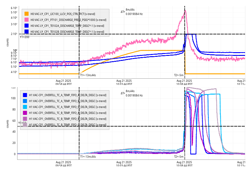
2025-08-21 15:34 UTC Ramped over from using OSEM-only to using GS13 Y Estimator and "light" OSEM damping.
2025-08-21 16:05 UTC Turned OFF yaw estimator (back to ), turned ON P estimator.
2025-08-21 16:36 UTC Turned ON yaw estimator, P estimator remains ON. Woo!
2025-08-21 16:50 UTC Both estimators turned OFF (and immediately, calibration measurements start)
- IFO reached nominal low noise at 14:10 UTC (so IFO is ~1.25 hours into thermalization, which we typically quote to be 3.0 hours "done" [not 1/e time constant])
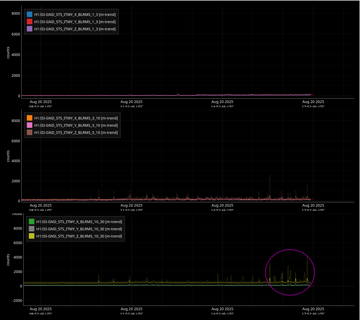
- EQ band is low at 0.02 [um/s]_RMS (most recent EQ was 4.5 [hr] ago; 5.8 [mag] just north of Japan)
- uSeism band is medium (for LHO summer) at 0.1 [um/s]_RMS
- Wind is less than 5-10 [mph]
2025-07-01 These are in use are after the M1 OSEMs have had their satamps upgraded (LHO:85463,
2025-07-14 The upgraded satamp response was perfectly compensated with measured z:p's from testing in the EE lab LHO:85746)
2025-07-29 These are in use after the M1 OSEMs have had their absolute calibration improved (LHO:86070)
After the above, HAM5 / SR3 estimator design was informed by the following measurements
- 2025-07-29 (In the presence SR3 SUSPOINT Basis ISI EXC; (ISI GS13s projected to SR3 SUSPOINT Y) to (SR3 M1 DAMP Y) LHO:86075,
- 2025-08-05 M1 to M1 LHO:86202,
- 2025-08-05 (In the presence SR3 SUSPOINT Basis ISI EXC; (ISI GS13s projected to SR3 SUSPOINT P) to (SR3 M1 DAMP P) LHO:86203
- 2025-08-05 M1 to M1 LHO:86203
Design of estimator and blend filter aLOGs are quoted below by each filter
2025-08-19 Oli installed / configured these estimators this past Tuesday (LHO:86455)
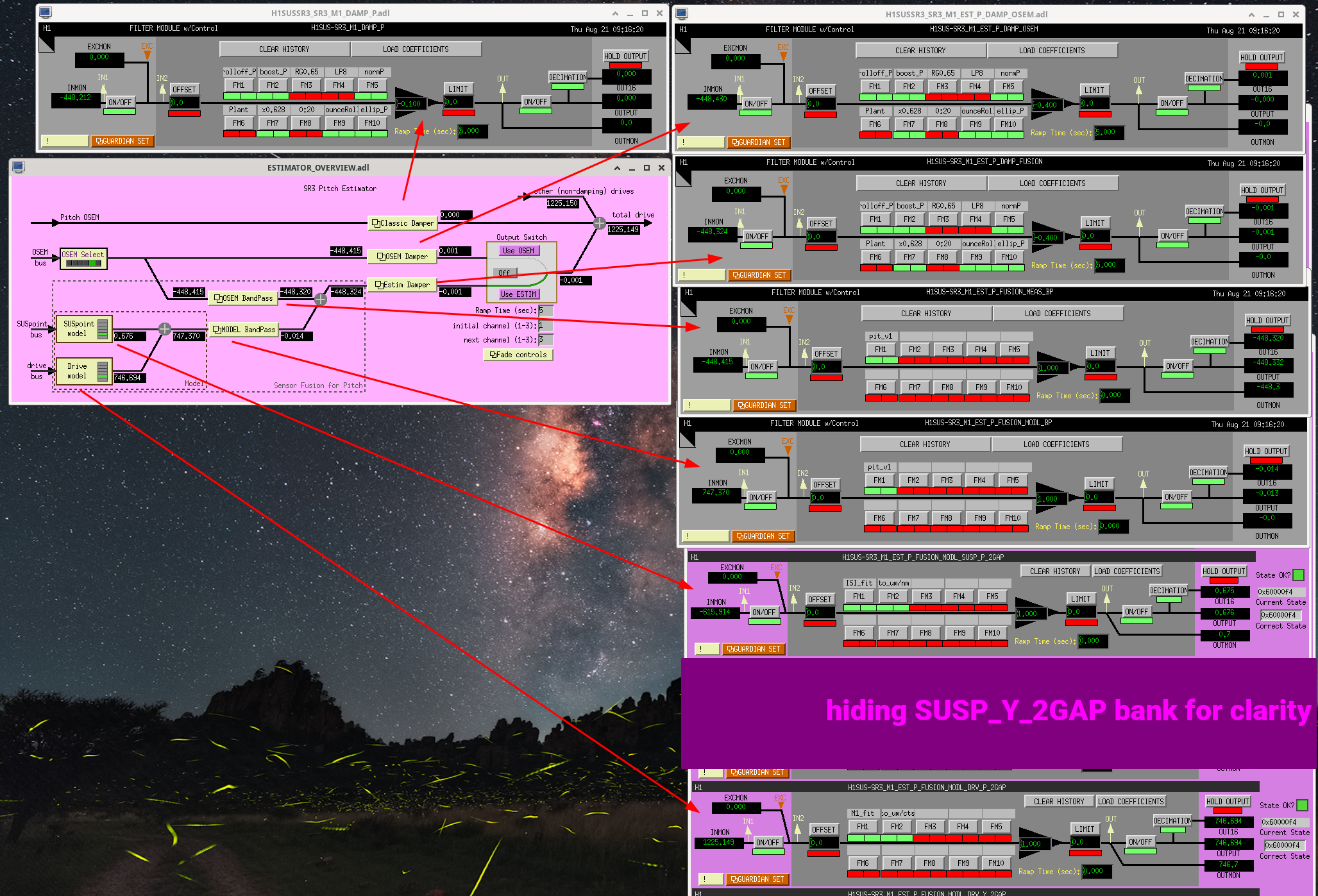
::: PIT FILTERS :::
Design aLOG: LHO:86430
M1_EST_P_FUSION_MODL_SUSP_P_2GAP "ISI_fit" FM1 EPICS Gain: +1.0
sos(-0.001012906275385808, [-2.0001366554573741; 1.000136668010563;
-1.999948594076947; 0.99994860612347214;
-1.999955359352324; 0.99995565554604537;
-1.999976011494571; 0.99997638571005953;
-2.000046972353724; 1.0000477507088701;
-1.9999816676161819; 0.99998231095588275;
-1.999807905043806; 0.9998079477319114;
-1.9999858561539881; 0.9999859195985662;
-1.999989374293667; 0.99998949933234416;
-1.9999885936664199; 0.99998867482680542;
-1.9999967240112111; 0.99999852427171887;
-1.9999908757192211; 0.99999261046439736])
"to_um/nm" FM2
zpk([],[],1.000000000000000,"n") %% Yes, this is a gain of 1.0 and thus is not doing anything. This is vestigial. Calibration has been absorbed into the "ISI_fit."
M1_EST_P_FUSION_MODL_DRV_P_2GAP "M1_fit" FM1 EPICS Gain: +1.0
sos(6.9937614616314464e-08, [1.9999999999998279; 0.99999999999995282;
-1.9999796747664531; 0.99998031671408905;
-1.9999989658263551; 0.99999907355206619;
-1.999984525961469; 0.99998458794634182;
-1.999972378962787; 0.99997245232369414;
-1.999986427026998; 0.99998650968797875;
-1.9999982894453341; 0.99999986582789491;
-1.9999908361882079; 0.99999257469114344])
"to_um/cts" FM2
zpk([],[],1.000000000000000,"n") %% Yes, this is a gain of 1.0 and thus is not doing anything. This is vestigial. Calibration has been absorbed into the "M1_fit."
Design aLOG: LHO:86452
M1_EST_P_FUSION_MEAS_BP "pit_v1" FM1 EPICS Gain: +1.0
sos(0.1000427204344847, [-0.99977476062437198; 0;
-0.99998082542398548; 0;
-1.999507407187904; 0.99950802568624952;
-1.9999459253790719; 0.99994656777201008;
-1.9997448445054919; 0.99974638260765558;
-1.9999542865584909; 0.99995602687005281])
M1_EST_P_FUSION_MODL_BP "pit_v1" FM1 EPICS Gain: +1.0
sos(0.8999572795655153, [-1; 0;
-0.99998082542398548; 0;
-1.999987516253469; 0.99998815869468505;
-1.9999459253790719; 0.99994656777201008;
-1.9999884578241209; 0.99999019525631272;
-1.9999542865584909; 0.99995602687005281])
Copies of M1_DAMP_P: (EPICS Gain: -0.1)
P_DAMP_OSEM EPICS Gain: -0.4
P_DAMP_FUSION EPICS Gain: -0.4
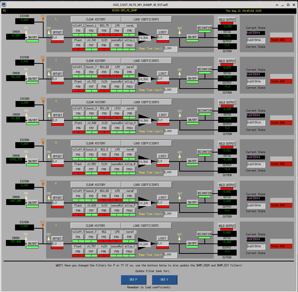
The filters ON in each of these damping loop controller filter banks
rolloff_P soft roll-off of sensor noise zpk([0;2;5],[20;20;30;30],0.005,"n")
boost_P extra gain at first Y resonance zpk([0.415914+i*0.587721;0.415914-i*0.587721;0.67;0.77],[0.246255+i*0.676579;0.246255-i*0.676579;0.131518+i*0.707886;0.131518-i*0.707886],1,"n")
norm_P nominal unit conversion from um to ADC ct zpk([],[],43.478,"n")
x0.628 gain adjustment from absolute calibration gain(0.628)
bounceRoll highest V and R mode notch tailored for SR3 ellip("BandStop",4,1,60,27.5,28.0)ellip("BandStop",4,1,60,45.0,45.5)gain(1.25893)
ellip_P aggressive roll-off of sensor noise zpk([0.64975+i*9.7463;0.64975-i*9.7463],[1.22183+i*5.87428;1.22183-i*5.87428;2.7978],1,"n")
(total OSEM gain or OSEM+Estimator gain of -0.5 for P, the prior-to-estimator "nominal" gain we'd been running since Aug 15 2023 LHO:72249)
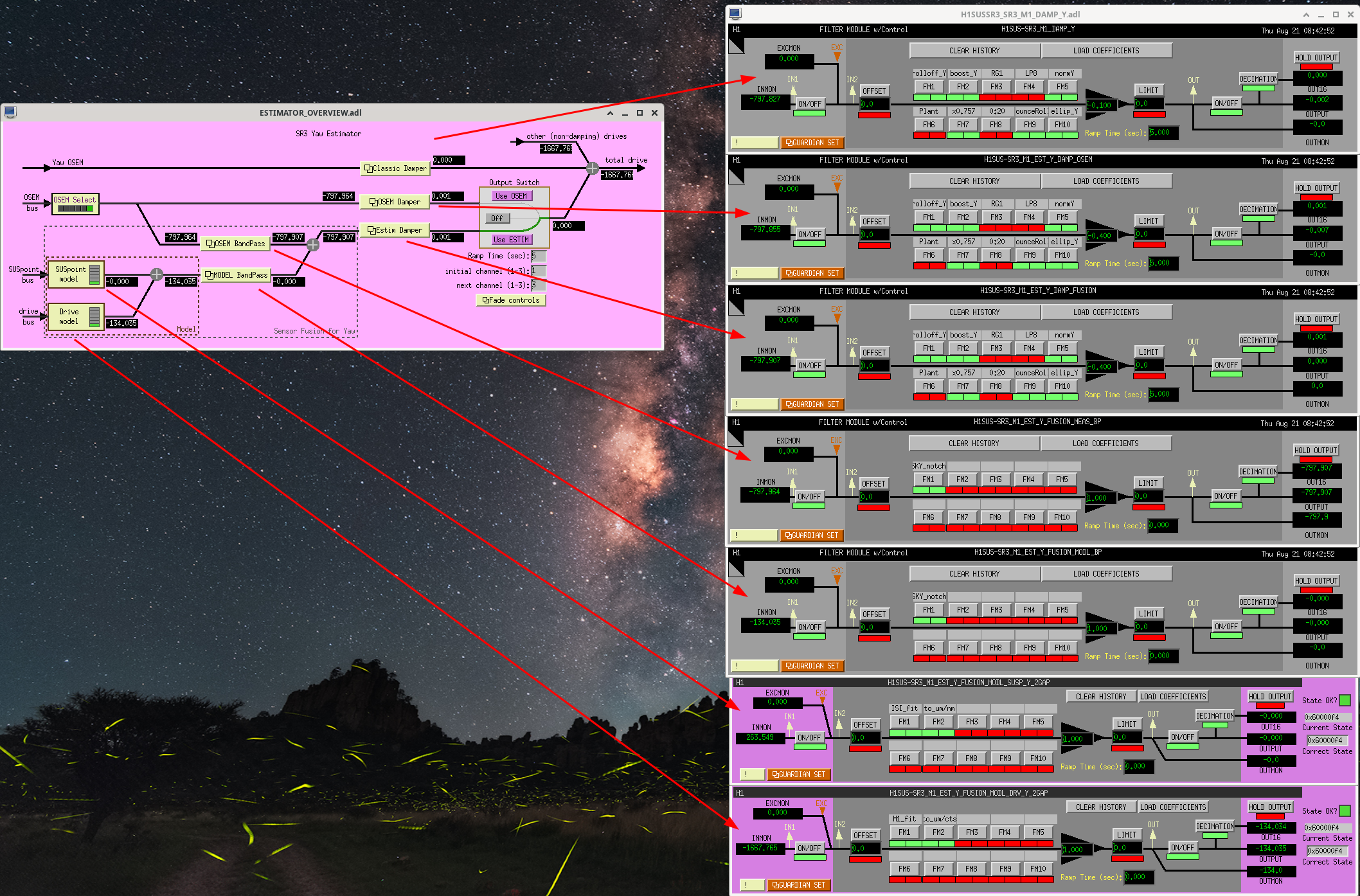
::: YAW FILTERS :::
Design aLOG: LHO:86233
M1_EST_Y_FUSION_MODL_SUSP_Y_2GAP "ISI_fit" FM1 EPICS Gain: +1.0
sos(-0.00097333255316384561, [-2; 0.99999999999999989;
-1.999987505826812; 0.99998828408658169;
-1.9999917387445989; 0.99999222786356268;
-1.999991053658418; 0.99999120602937952;
-1.9999951079581699; 0.99999667180704854;
-1.9999907068801011; 0.99999239185345823])
"to_um/nm" FM2
zpk([],[],1.000000000000000,"n") %% Yes, this is a gain of 1.0 and thus is not doing anything. This is vestigial. Calibration has been absorbed into the "ISI_fit."
M1_EST_Y_FUSION_MODL_DRV_Y_2GAP "M1_fit" FM1 EPICS Gain: +1.0
sos(1.1347068995497109e-08, [2.000000000001652; 0.99999999999677247;
-1.9999881576357379; 0.99998893434766245;
-1.999998372312229; 0.99999974909962519;
-1.99998928164089; 0.99999097015263916;
-1.999998867104356; 0.99999912434806359;
-1.99999256126361; 0.99999271377731203])
"to_um/cts" FM2
zpk([],[],1.000000000000000,"n") %% Yes, this is a gain of 1.0 and thus is not doing anything. This is vestigial. Calibration has been absorbed into the "M1_fit."
Design aLOG: LHO:86265
M1_EST_Y_FUSION_MEAS_BP "SKY_notch" FM1 EPICS Gain: +1.0
sos(0.000183409288171444, [1; 0;
-0.99996165121563274; 0;
-1.999942013670952; 0.99994237961280041;
-1.999812801308257; 0.99981448778963355;
-1.9999004183717279; 0.99990166730434937;
-1.999852310365053; 0.99985308742131895;
-1.9999736341441301; 0.99997367996470554;
-1.9999216555380299; 0.99992180839221256])
M1_EST_Y_FUSION_MODL_BP "SKY_notch" FM1 EPICS Gain: +1.0
sos(0.9998165907118286, [-1.0000000000000011; 0;
-0.99996165121563274; 0;
-1.999961208202631; 0.99996289480915956;
-1.999812801308257; 0.99981448778963355;
-1.9999698386597631; 0.99997061576169488;
-1.9998523103650541; 0.9998530874213194;
-1.9999842083331081; 0.99998436119207135;
-1.9999216555380299; 0.99992180839221256])
Copies of M1_DAMP_Y: (EPICS Gain: -0.1)
Y_DAMP_OSEM EPICS Gain: -0.4
Y_DAMP_FUSION EPICS Gain: -0.4
rolloff_Y soft roll-off of sensor noise zpk([0;1],[20;30;30],0.01,"n")
boost_Y extra gain at first Y resonance zpk([0.9;1.1],[0.173648+i*0.984808;0.173648-i*0.984808],1,"n")
norm_Y nominal unit conversion from um to ADC ct zpk([],[],43.478,"n")
x0.757 gain adjustment from absolute calibration gain(0.757)
bounceRoll highest V and R mode notch tailored for SR3 ellip("BandStop",4,1,60,27.5,28.0)ellip("BandStop",4,1,60,45.0,45.5)gain(1.25893)
ellip_Y aggressive roll-off of sensor noise zpk([0.97195+i*9.7195;0.97195-i*9.7195],[1.0264+i*4.9347;1.0264-i*4.9347;2.7978],1,"n")
(total OSEM gain or OSEM+Estimator gain of -0.5 for Y, the prior-to-estimator "nominal" gain we'd been running since Aug 15 2023 LHO:72249)


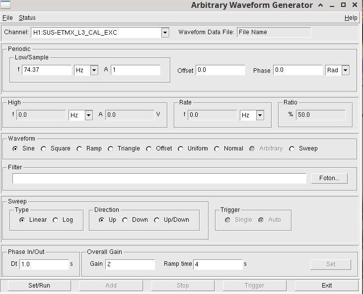
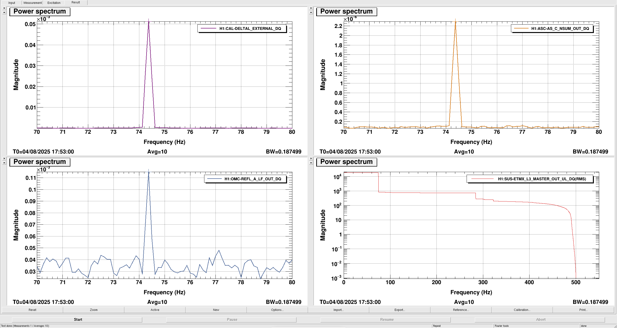
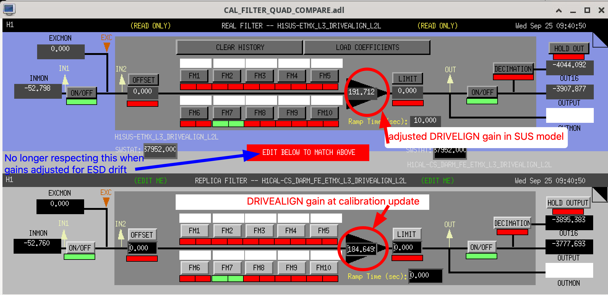 Somewhere along the way I updated the TST drivealign gain parameter in the pyDARM model even though I shouldn't have. At this point, I don't recall if I was confused because the two sites operate differently or if I was just running a test and left this parameter changed in the model template file by accident and subsequently forgot about it. In any case, the drivealign gain parameter change made its way through along with the actuation delay adjustments I made to compensate for both the new ETMX DACs and for residual phase delays that haven't been properly compensated for recently (