Addressed TCS Chillers (08:20 - 8:28 AM PST today/Mon)
TITLE: 03/18 Day Shift: 15:00-23:00 UTC (08:00-16:00 PST), all times posted in UTC
STATE of H1: Lock Acquisition
OUTGOING OPERATOR: None
CURRENT ENVIRONMENT:
Wind: 3mph Gusts, 2mph 5min avg
Primary useism: 0.08 μm/s
Secondary useism: 0.31 μm/s
QUICK SUMMARY:
Patrick performing Initial Alignment -no issues
5.2Mag EQ near Tonga/New Zealand area - no intervention taken
15:19 Resume locking H1
Dan, Craig, Georgia, Alexei, Anamaria
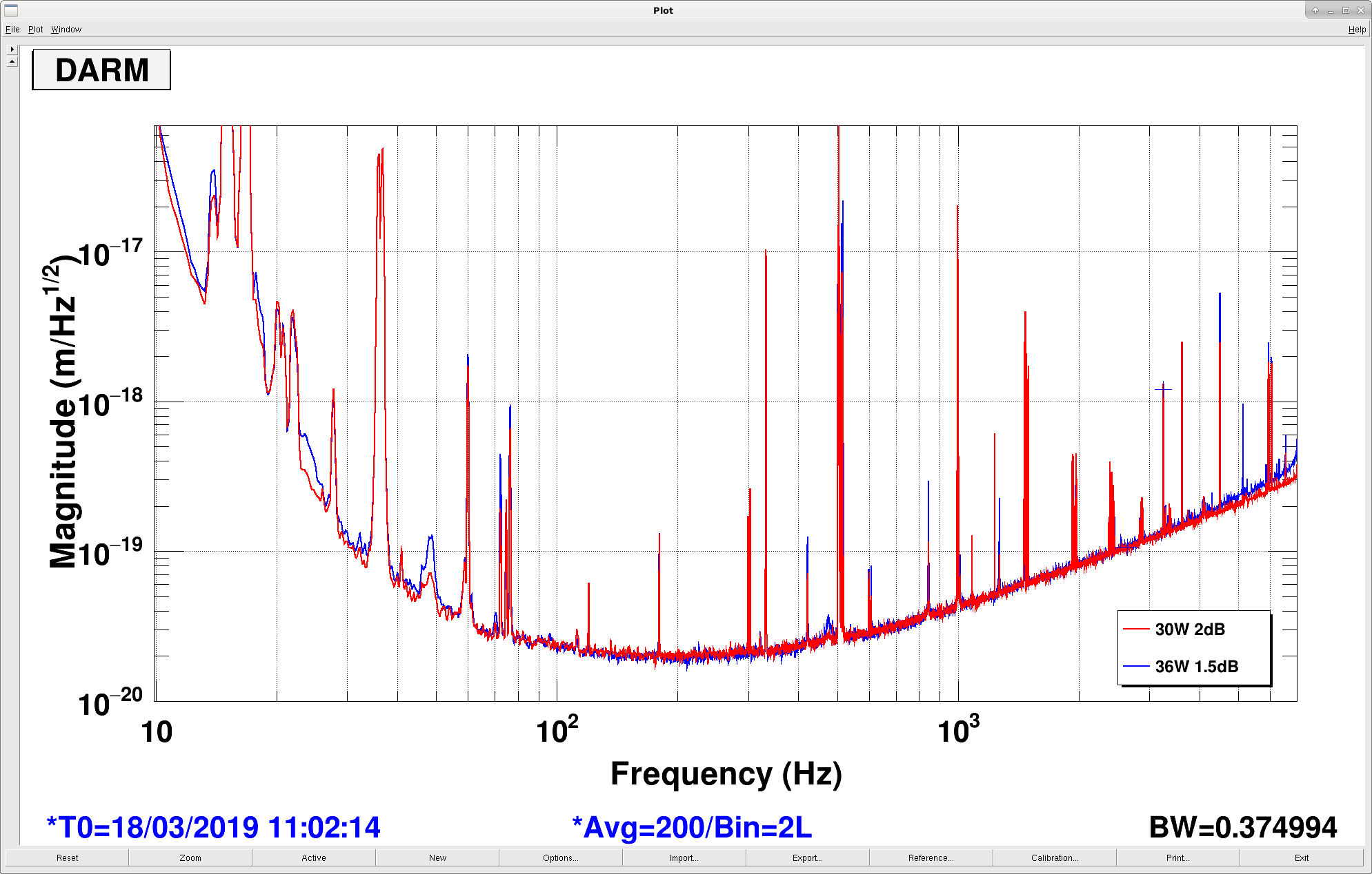
We decided to try a higher power lock now that a lot of things have been smoothed out. We were able to easily power up to 36W (we did it at the POWER_30W step, before low noise ASC settings and ESD). We ran two sets of lines, low frequency and high frequency for intensity and frequency noise coupling. We also ran a 9 MHz EOM line.
- For a while we ran without ISS DC_COUPLED for unrelated reasons, but once Georgia engaged it the ISS line at 70ish MHz was reduced by a factor of 10.
- We paranoidly increased the PRCL gain from 12 to 15, reduced MICH P gain from -1.2 to -1 and reduced CHARD P from 2.0 to 1.8. Unclear if it was necessary.
- We set the SRCL length offset to what Sheila had chosen earlier for optimized squeezing, but we were only able to get 1.5 dB instead of the 2 dB she had. We didn't try to optimize anything about it.
- We raised the CM gain 3dB and saw the DARM noise at high frequency get reduced some. We could try more maybe, but we should measure the loop.
- We overall lost 4% of optical gain (says maybe-ok-kappaC) but we recovered 1% with a bit of spot move (Dan will post details). We put this into CAL DARM ERR and ran a pcal broadband to confirm the calibration was correct.
- Some numbers:
Optical gain decrease: 3%
PRG decrease: 3.3%
X arm increase: 17%
Y arm increase: 16%
AS_C increase: 16%
REFL increase: 8%
POP 18 decrease: 6%
POP90 decrease: 4%
- The ISS low frequency line increased by x1.4 but the high frequency line did not change.
- The frequency noise low frequency line did not change, but the high frequency line increased by x2.2. This is good because it means we did not make the frequency noise worse in the bucket.
- The 9 MHz line at 72.3 Hz increased by x2.4. Hopefully we can tune this coupling back down.
- The noise at the 48 Hz bump and maybe in the 20-35 Hz range is a bit worse, but the overall noise is quite comparable to the fully tuned 30W state.
We think that with some TCS tuning (we did none so far!) and squeezer re-optimization we can surpass the 30W performance.
Note on ISS 2nd loop DC coupling:
The first time we tried going through LASER_NOISE_SUPPRESSION at 36W we had an aggressive excitation on the ISS 2nd loop. This meant when the second loop was DC coupled the output of the AC coupling servo was held at a large value and pushed the ISS diffracted power to zero, causing almost-instant lockloss. Lesson learnt: do not try to DC couple the ISS with a big excitation.
The second time time we went to ISS_DC_COUPLED we lowered some gains to compensate for the extra power:
- PSL-ISS_SECONDLOOP_REFERENCE_IN_MTRX_1_4 was 125 (from 150 @30W)
- lscparams.ISS_FinalGain was 5 dB (from 7dB @30W).
DC coupling was seamlessly engaged. For future commissioners: I have returned the parameters to their 30W values in guardian, and the has been loaded.
DARM plant flips back to antispring detuning with 36 W and SR3 heater on at 5W. This could be why our range did not improve as much as hoped. See 47604
After some spot moves we managed to max out the arm powers with 181kW and 167kW in Y and X respectively, up ~2kW.
| Mirror | P2L start | P2L end | Y2L start | Y2L end |
|---|---|---|---|---|
| ITMX | -3.98 | -3.6 | 0.26 | -0.02 |
| ITMY | -3 | -2.6 | -0.2 | 0 |
| ETMX | 4 | 4.98 | 4.0 | 5.1 |
| ETMY | 4.5 | 4.7 | 2.5 | 2.18 |
The largest change was in ETMX yaw position, which moved slightly further away from the point absorber there. This is where we gained the most. The spots moved down slightly on the ITMY point absorber. I thought I had some nice HWS images of the ETMX point absorber reducing, however it was being ruined by a dead pixel.
I also tried a brief SR3 heater test. For the whole 36W test the heater was at 5W. I dropped it to zero for 20 minutes but the RF18 dropped very quick, from 47 to 44. This was preceded an ADS instability at 0.012Hz, it was stopped by just switching off all the ADS channels, however switching them back on results in the the instability ringing back up. Given that I didn't tune any of the TCS for 36W yet, it's no surprise that 9MHz is affected by SR3 due to too much cross coupling from PRCL to SRCL.
Hopefully these new spot positions work at the usual 30W settings tomorrow. I have left ADS off, some residual of the 0.012Hz oscillation is still visible, we'll see if it survives the night...
Since the beam spot 'positions' in Dan's alog are quoted in A2L gain numbers, here I tabulate what that means for spot position in mm. Note that I am quoting today's current values for the A2L gains, which differ very slightly from those quoted above.
Sign convention for spot position in mm: up (+Vert on SUS screens) is positive for pitch and farther to the left (+Trans on SUS screens) is positive for yaw.
| Pit P2L gain | Pit [mm] | Yaw Y2L gain | Yaw [mm] | |
| ITMX | -3.76 | 20.8 | -0.17 | -0.6 |
| ITMY | -2.6 | 15.6 | 0.0 | 0 |
| ETMX | 4.85 | -18.3 | 4.95 | 18.2 |
| ETMY | 4.55 | -16.9 | 2.03 | 7.5 |
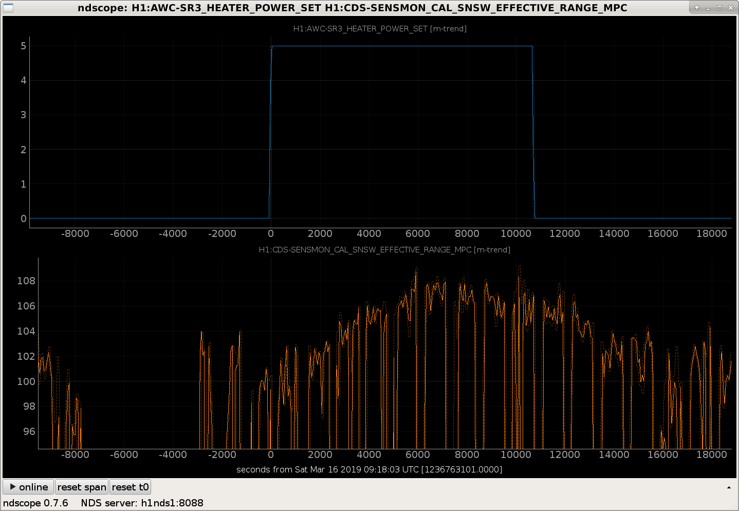
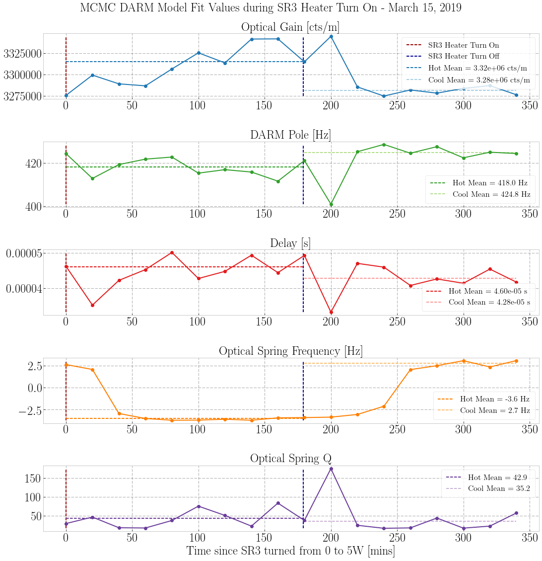
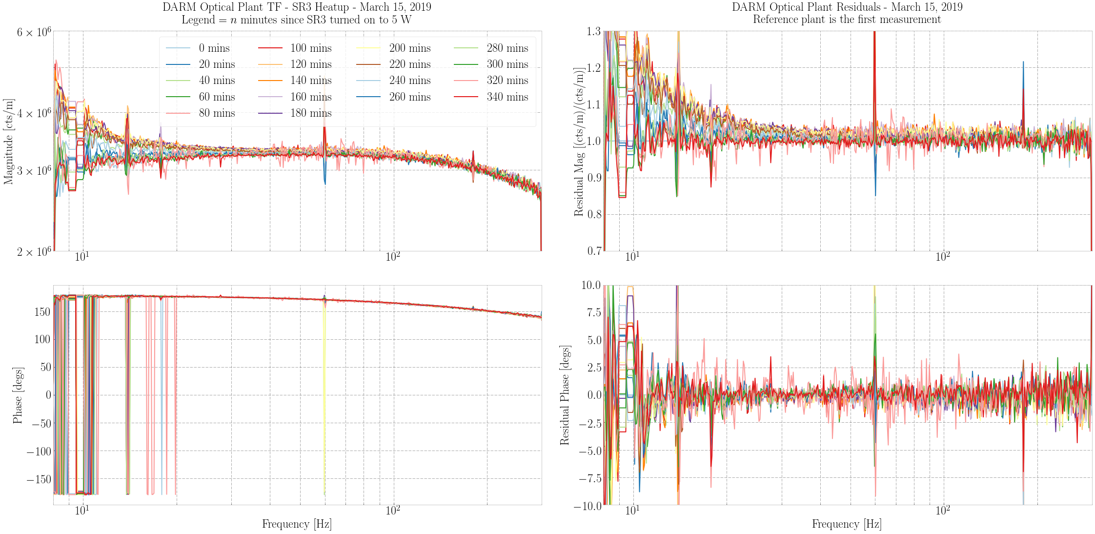
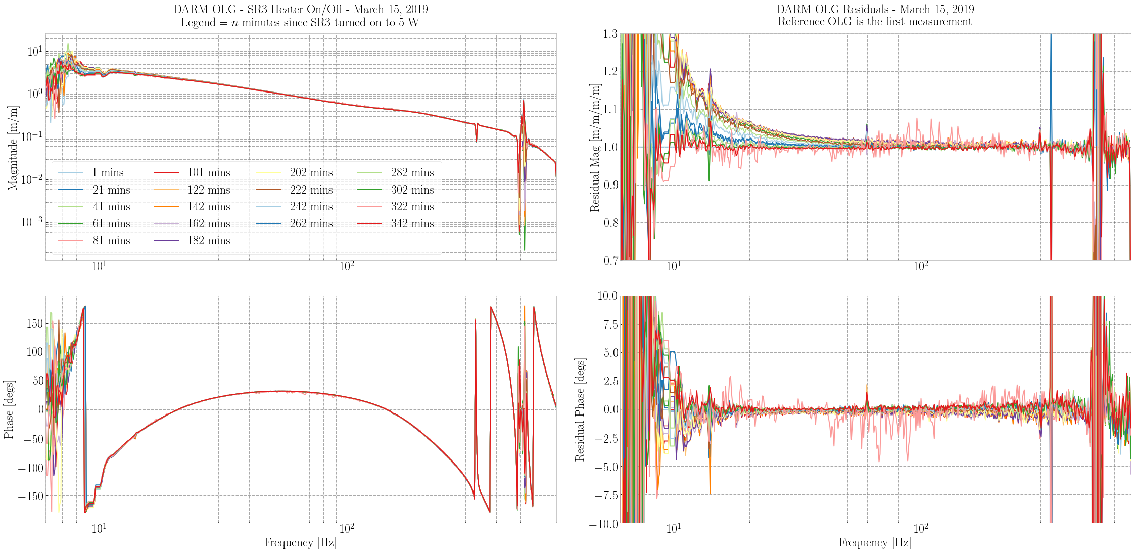
It seems as though the range increases we've seen with turning on the SR3 ring heater are at least partially real and not just due to miscalibrations, according to Georgia and Dan. This alog attempts to explain what about the DARM plant changes when the SR3 is heated, and why it wins us megaparsecs. It appears that turning on the SR3 ring heater from 0 W to 5 W flips the sign of the DARM detuning, as witnessed by the DARM optical spring. Otherwise the DARM plant has ~1% changes in the optical gain and DARM pole between on and off states. As a reminder, DARM is set for resonant sideband extraction (RSE), meaning the nominal phase of the DARM coupled cavity is 90 degrees. This is accomplished by setting the SRC length such that carrier is antiresonant. "Detuning" refers to the fact that the SRC is not actually tuned to exactly 90 degrees, and this tuning can change the DARM response. The DARM optical spring relies on the sign of the detuning: in one case, the optical spring is restoring like a normal spring. In the other, we have an antispring behavior where the further we are off resonance, the antispring pushes us away even harder. For years at LIGO Hanford, we have operated with an nontrivial DARM antispring. I analyzed the DARM plant measurements during the SR3 heater turn on from two nights ago. The DARM plant measurements were taken every twenty minutes, starting when we turned on the SR3 heater to 5 W, then continuing through three hours later when turning the SR3 heater back to 0 W. (SR3 Heater turned on = 2019-03-16 09:18:03 UTC, SR3 Heater turned off = 2019-03-16 12:17:59 UTC) I recovered 18 DARM plants, and 18 DARM OLGs. The DARM plant clearly goes through a large change at low frequencies. DARM UGF = 54 Hz. (Attachments 4 and 5) I modified my DARM plant model to allow for both positive and negative detuning (see Appendix D of Hall for more), and fit each measurement via MCMC. (Attachment 2, or the PDF) Somewhere between 20 and 40 minutes after turning on the heater, the DARM optical spring flips sign. I also plotted the DARM fit parameters as a function of time. (Attachment 3) While the SR3 heater is hot (at least 40 minutes after turning on the heater): - The optical gain of the DARM plant increases by about 1%. - The DARM pole decreases from 425 Hz to about 418 Hz. - The delay increases by 7% (from 43 to 46 μs) - The optical spring changes sign from 2.7 to -3.6 Hz. - The optical spring Q has no discernible change given its noise. The increase in optical gain will help kill shot noise everywhere, while the detuning sign flip increases the DARM response significantly (~8% at 20 Hz) at low frequency. The decrease in the cavity pole will decrease DARM response at frequencies beyond the DARM pole. Overall, the net effect is a significant gain in range. Since we are now running with the SR3 heater on all the time, and are potentially going to power up to 36 W, our DARM model which assumes an antispring detuning may need to be updated.
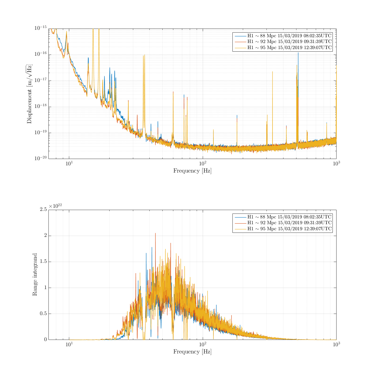
The SR3 tests last week showed broadband improvements in DARM below 40 Hz in one lock last week, and below 200 Hz in another. I made some BNS range integrand plots at a few points during Friday Thursday night/Friday morning's SR3 heater test to see where in the spectrum our range improvement was coming from, and as sanity check that we're not being fooled by the changing calibration. Conclusions:
- within an hour of the SR3 heater being turned on we have significant improvement in DARM below 30 Hz, which gives us ~4 Mpc
- later in the lock, once the heater has stabilised, we get sensitivity improvement from 40-100 Hz
- the 48 Hz wandering peak was (in this lock) eating ~2Mpc
- while the calibration changed during the lock that effect is small compared to the real change in the displacement
Craig explains the physics behind the range increase here.
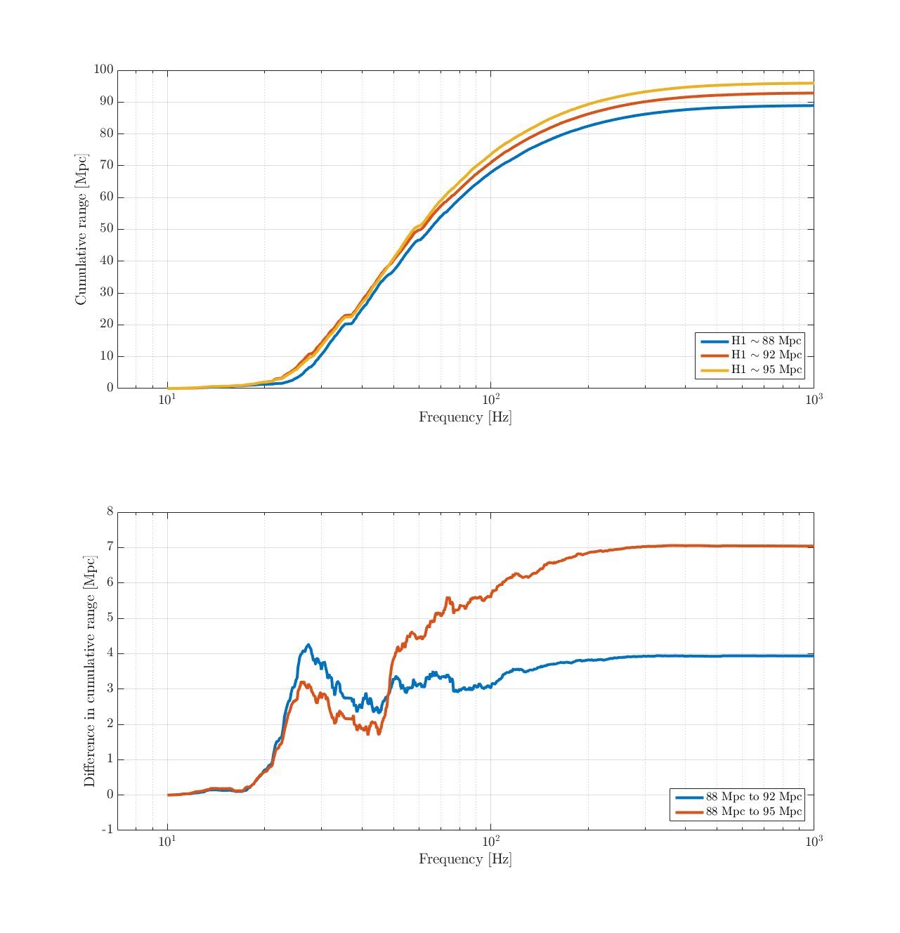
First attachment is DARM spectra and range integrands for 3 points in the same lock. Blue is before the SR3 heater is turned on, red is while the heater is still thermalising (and roughly around the same time as the PCAL to DARM sweep was run), yellow is later in the lock once the SR3 temperature had stabilised.
The most noticeable difference is the low frequency improvement in the first hour of the heater being turned on. The 48 Hz lump also improves between these three locks but I''m not sure if that is related to the SR3 heater at all. Finally the 72.3 Hz line (injected into the 9MHz RIN excitation point to monitor its coupling to DARM) decreases dramatically.
The second attachment top plot is the cumulative range in the three spectra, and the bottom plot is the difference in cumulative range between them. This shows that the initial range improvement (in the first hour and a half of the lock) is almost entirely attributable to the noise below 30Hz, as well as some possible improvement above 100 Hz. The red trace, comparing the 88 and 95 Mpc times, shows a 2Mpc jump at 48 Hz since the time I got for 95 Mpc also coincided with low 48Hz lump activity.
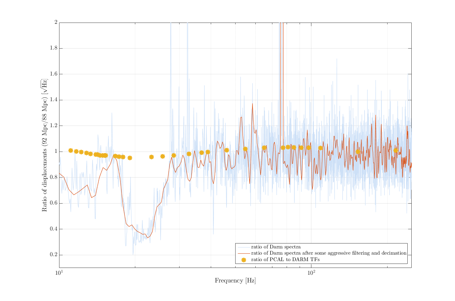
Craig pointed out that from Dan's PCAL to DARM sweeps, the relative calibration changed between the two spectra. Below 40Hz in our SR3-heater-on spectrum we are underestimating DARM and overestimating the BNS range. Above 40 Hz our actual calibration is better in the 94 Mpc lock, and relative to the pre-SR3 heater time we are over estimating DARM and hence underestimating range. We had a look at the ratio of the PCAL-DARM transfer functions after and before the SR3 heater was turned on (i.e. the red and blue traces in this plot) to check that our range improvement is not due to the changing calibration. The ratio of PCAL-DARM sweeps before and after SR3 (yellow stars on the 3rd attachment), is much smaller than the ratio of DARM displacements before and after SR3 (red line). Assuming PCAL is the same at these two times, our improved displacement is real. Dan has already calculated that the difference in calibration at high frequency causes us to underestimate our range.
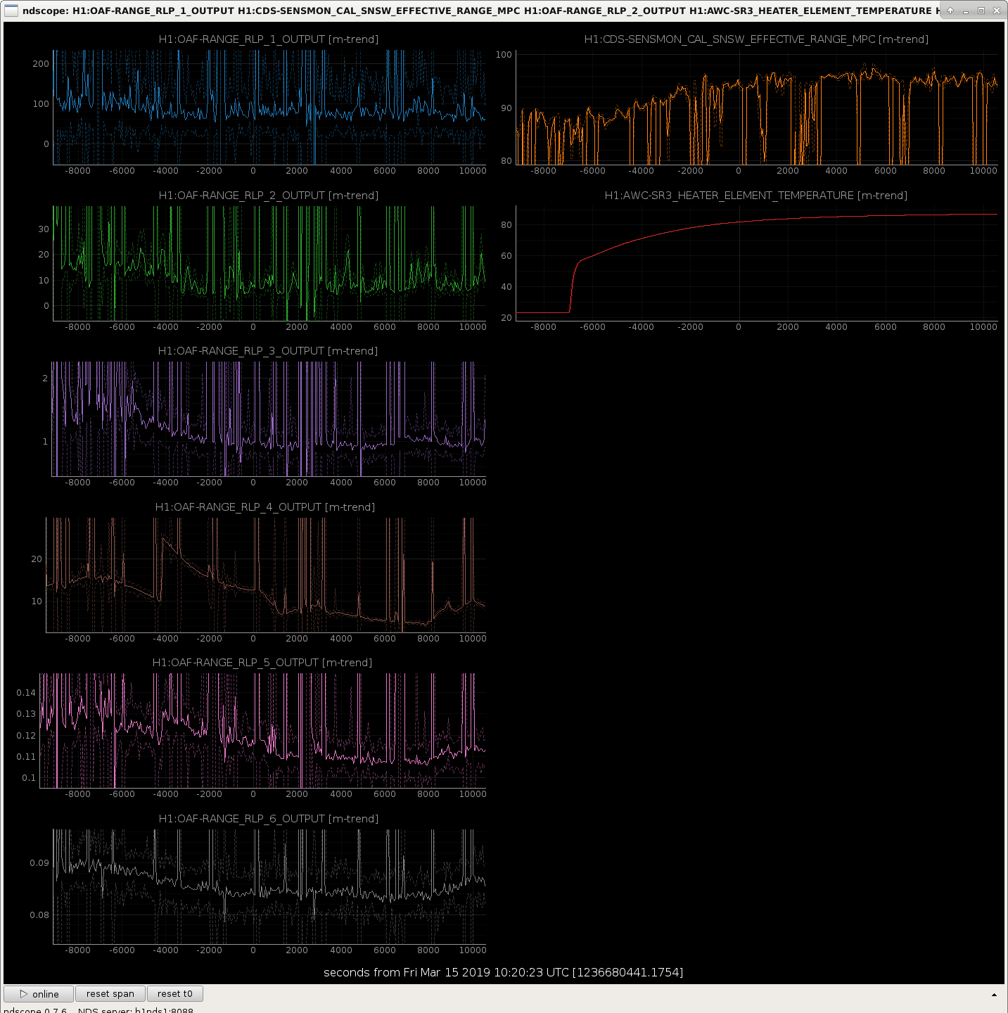
The final attachment shows the DARM BLRMS during this lock. The jumpy behaviour in the RLP 4 BLRMS (60-100Hz) is because it is dominated by the injected lines around 70 Hz.
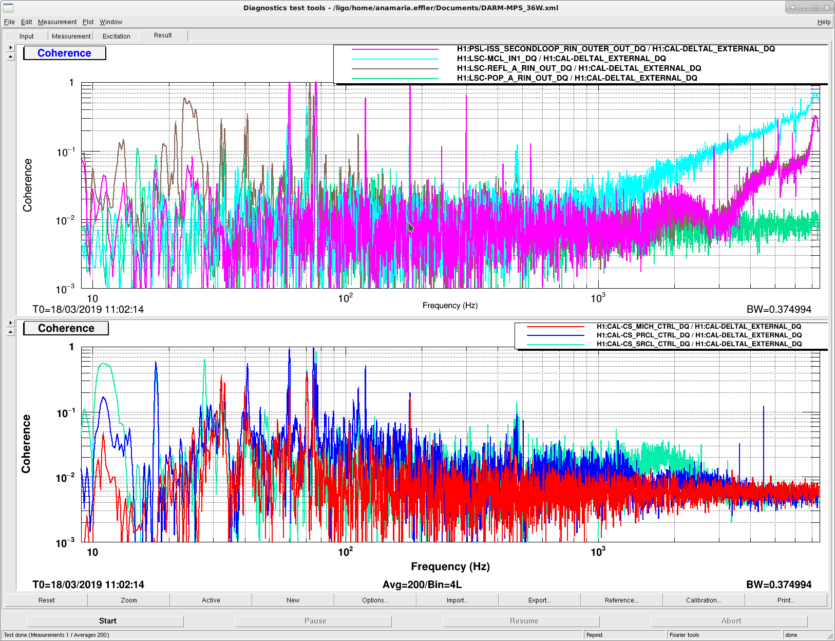
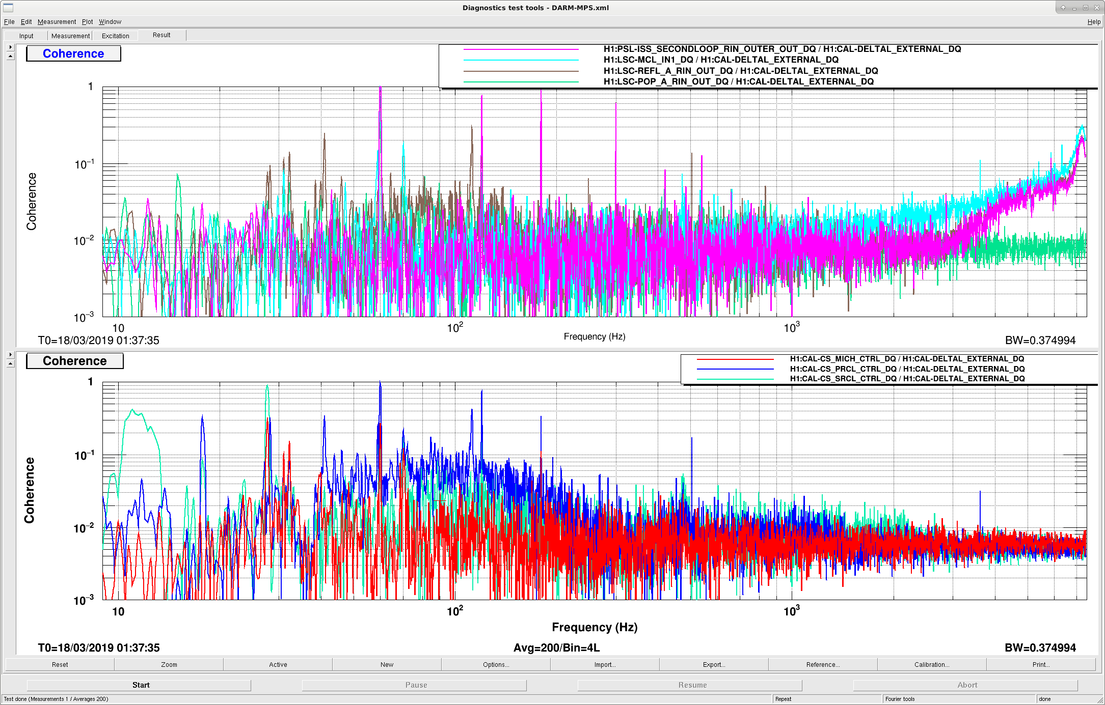
Just a record of DARM coherences with new DRMI sensing, squeezing and SR3 heater.
Sheila Dan Brown, Anamaria
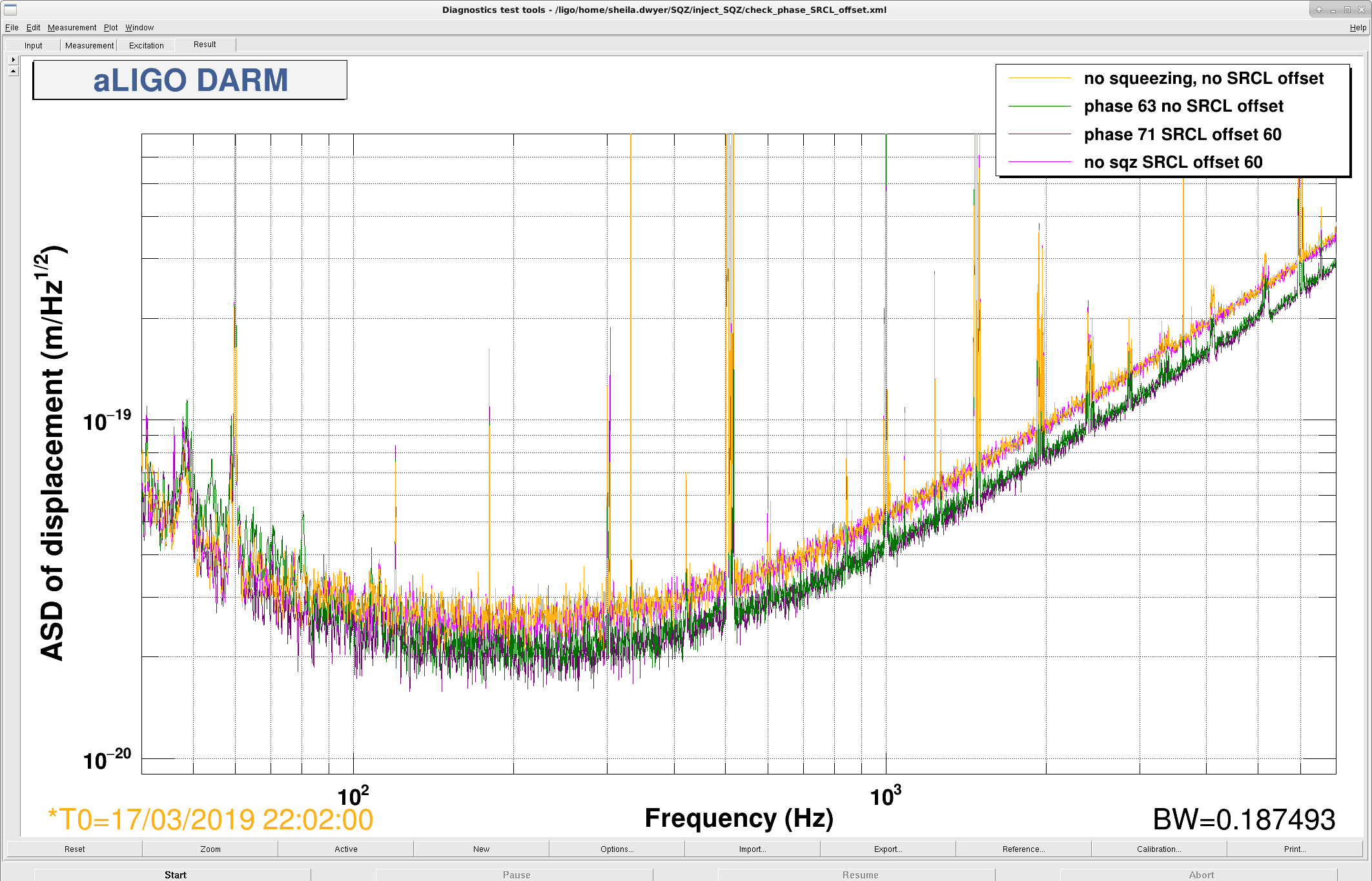
We did a quick test of squeezing for different SRCL offsets.
We found that the best squeezing is at a slightly different phase than we had been using, the total of OMC3 and HD3 (both of these are really used as 6MHz demods in the CLF chain) should be 63.66 degrees. The squeezing level isn't very sensitive to getting the phase exactly right, since we have a low level of squeezing. We cannot adjust the phase to better than ~5 degrees.
We next tried introducing an offset in the SRC cavity length, the improvement we saw was due to an improvement in the reference shot noise without squeezing, not due to squeezing. We did this with Jenne's SRC ASC offsets on 47585, and the level of squeezing we started with was a little bit worse than normal. Dan is now removing the SRC ASC offsets to see what happens.
There is a reference time for checking the cross corelation from 22:02-22:20 UTC on March 17th.
DanB, Sheila, Anamaria
As reported before, eg here, the calibration is pretty good down to some 30 Hz according to pcal broadband injection. kappa_pum and kappa_uim are reporting very different numbers from the nominal gains of 1 in the analog suspension calibration filters (~0.8) so we thought maybe these things are connected. We implemented them in the calibration filters of ANALOG ETMX L2 and L1, but after a pcal sweep, that made the low frequency calibration much worse; and the 35 Hz - ish pcal line visibly did not match anymore. We backtracked these changes.
Kappa_tst is 1 and the filter is 1, so at least that matches well.
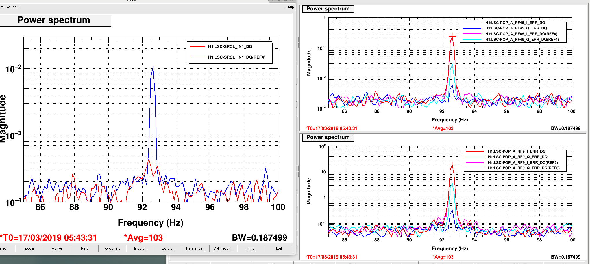
Yesterday I checked the POP sensing for MICH, PRCL and SRCL in full lock. I rephased POP9 and POP45 for a 92.6 Hz injection on PRM (because I found some already existing notches in the loops around this frequency). FTR, it's better to phase POP45I for PRCL, the dominant term, such that Q is free for MICH and then tune the PRCL subtraction in SRCL sensing. See plot attached of before (refs) and after phasing and retuning.
The POP9 phase change from -26 to -16.25 degrees and the POP45 phase changed from 6.1 to 12.0 degrees. The SRCL 9I element changed from 0.04 to 0.024. Changes have been absorbed in sdfs and guardian.
I then swept the loops to see the UGFS:
MICH - 8Hz
PRCL - 36 Hz
SRCL - 13.5 Hz
I saved the measurement templates in /opt/rtcds/userapps/release/lsc/h1/templates/ , names beginning with 190317*.xml
This should help with PRCL coupling into DARM, but we should recheck the SRCLFF performance.
Anamaria, Alexei, Danny, Dan
Tonight we have left the SR3 heater on at 5W. After redoing an initial alignment and some fine tuning of SRM/PRM for DRMI locking has been great. Jenne mentioned the other day that DRMI felt snappier with the SR3 heater on, I would agree with that. The last three locklosses we had DRMI was relocked again in a few minutes, DRMI has been catching on the first fringe each time, we've not had to touch anything. We have had no issues getting through to powering up to 30W. However, we haven't got past low noise ASC. SRC 1 and 2 are not converging as well as they have done previously, it almost looks as if they have an offset. Upon going through low noise ASC we eventually hit a point where we see some 2Hz ring up in MICH yaw, which appears in DSOFT+CSOFT pitch out. The ring up is quick and we lose lock in ~2s.
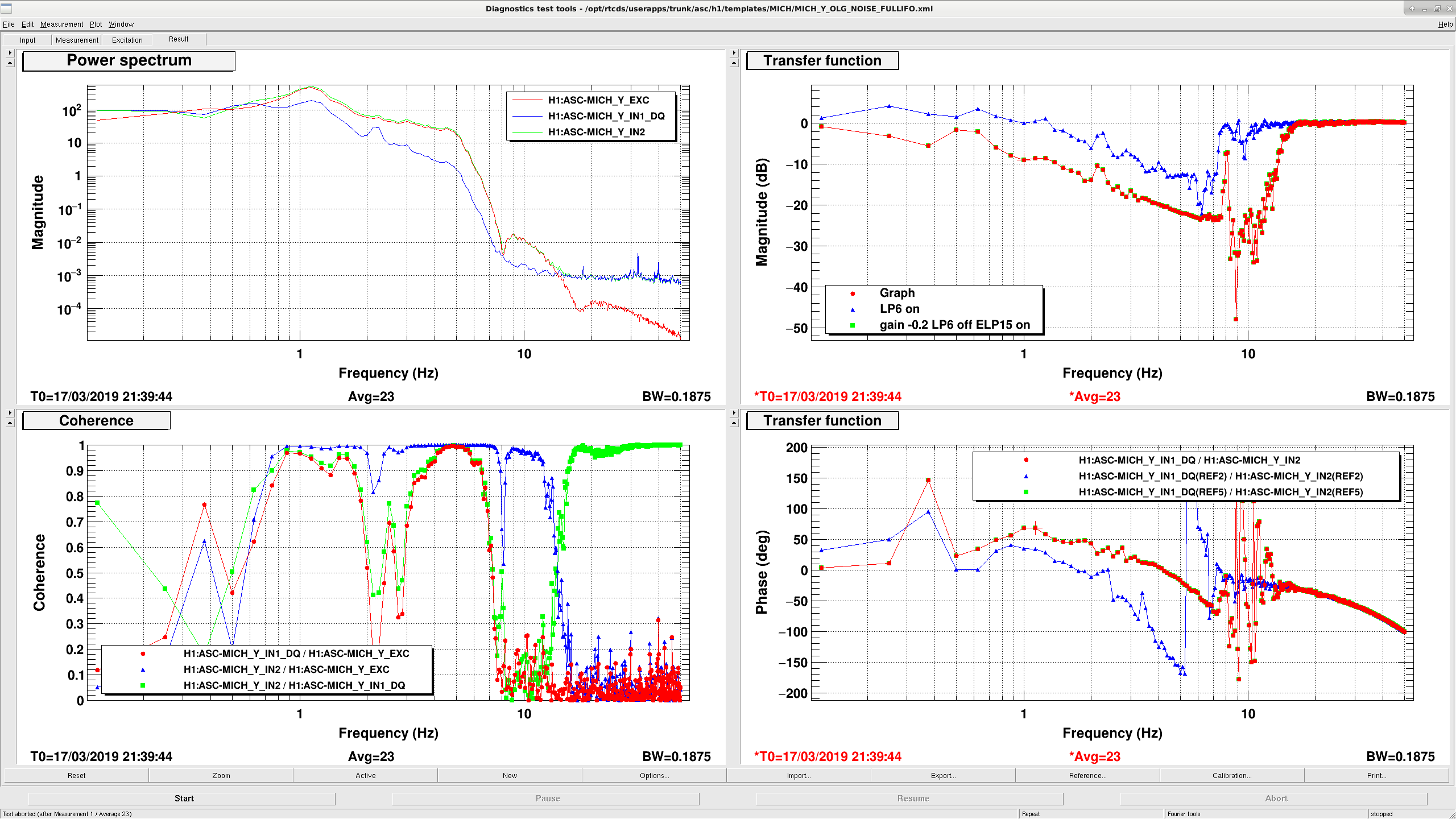
After stepping through low noise ASC we missed out MICHP FM8 and did not increase MICHY gain from -0.2 to -1. We then made it through to nominal low noise fine.
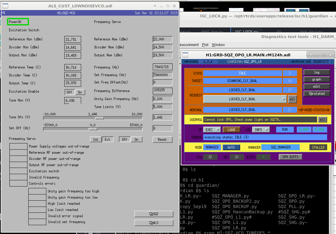
The squeezer did not engage when we got to NLN tonight. The 79.4MHz VCO was locking to 79.2MHz, and the guardian told us to adjust TUNE OFS. We disabled the servo and moved the slider to 79,4MHz. We could not enable the frequency servo without it driving back down to 79.2MHz. We tried to continue locking with the servo disabled and manually setting to 79.4, however, SQZ OPO guardian is now saying it "can't lock the OPO, check pump light on SQZT6". We are unsure what is going on.
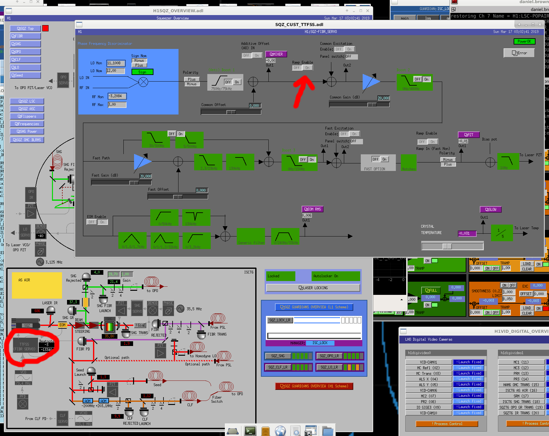
The solution to this issue was to ensure that the "Ramp Enable" switch in the TTFSS servo page was switched to "off".
I think this is the same issue as Friday night when TTFSS seemed to have jumped straight to "Acquire" without engaging the loop. The 79MHz message came up because when TTFSS was unlocked and the SQZ laser was not following the IMC VCO (the SQZ laser needs to follow the main IFO laser for the squeeze angle loop to close, the 3MHz one). The whole guardian automation was written assuming that TTFSS works reliably enough and it doesn't touch any of these TTFSS channels. TTFSS is all Beckhoff controlled.
Found myself stuck with this error tonight as well. Don't know how exactly I solved it but it seemed to be a combination of switching the error signal on the Slow frequency servo to "On" and possibly waiting at "Adjust Frequency" state for the SQZ_LO_LR guardian.
To check for 1 Hz comb.
EY: Mar. 17 3:07 UTC
EX: Mar. 17 4:12 UTC
I don't see much difference in the 1-Hz comb in DARM between data taken when the clocks were on (1:30-2:30 UTC - 1st attachment) and when they were off (5:00-7:00 - 2nd attachment). The noise floors are a bit different, but the heights of the 1-Hz lines are comparable.
Thank you Keith! Would you guys at LHO please reconnect them? We need these clocks working. Zsuzsa
Jenne, Sheila
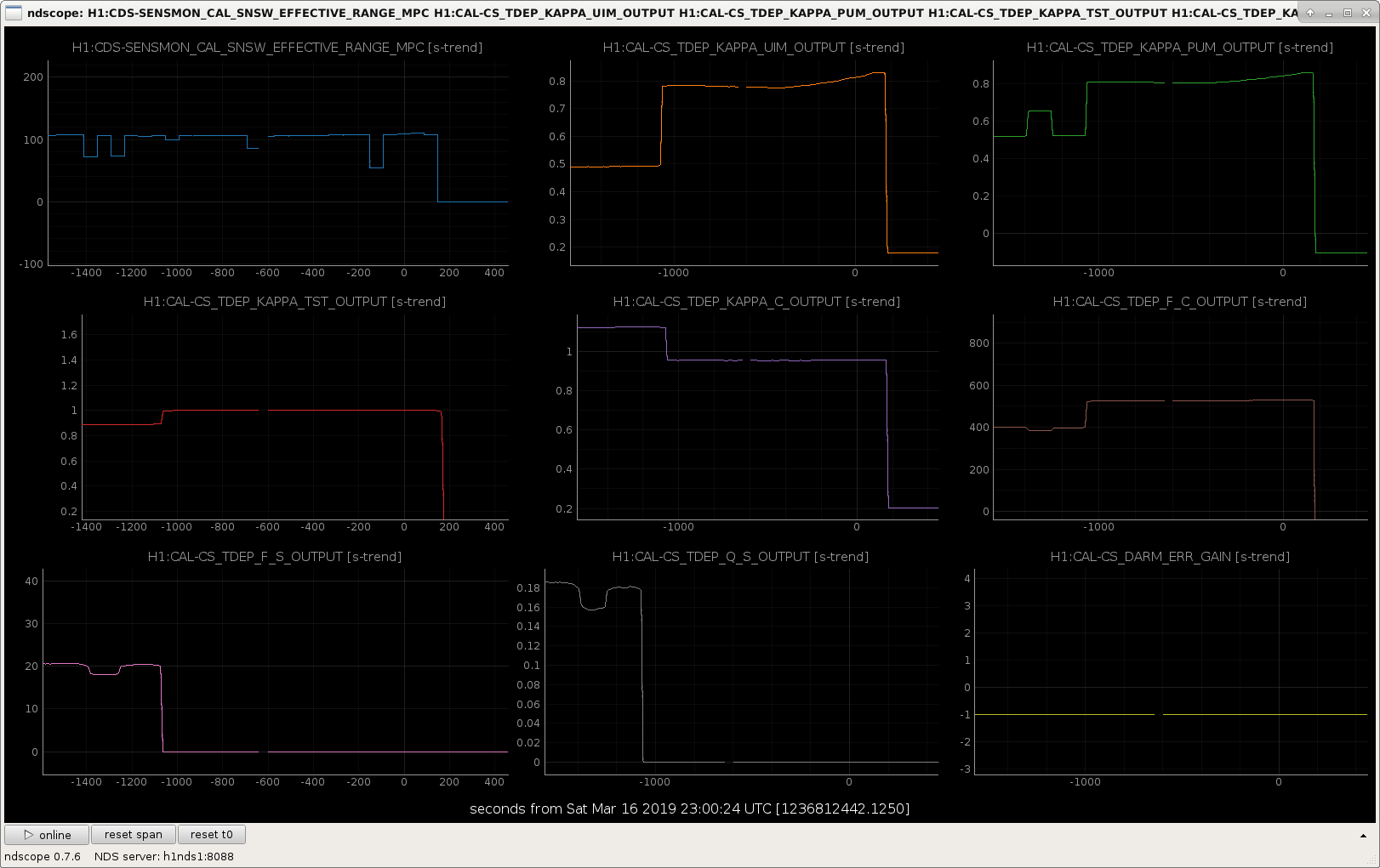
After a long talk with Keita and Joe B on the phone we have updated the calibration epics records that are used to calculate the kappas.
Joe walked us through how to update the epics records. We made a new copy of the paramter file in /ligo/svncommon/CalSVN/aligocalibration/trunk/Runs/O3/H1/params/modelparams_H1_20190316.py
We updated the validity time, modelDate, Optical gain, cavity pole, spring frequency and Q based on Craig's fit here. We measured a transfer function from DARM_IN1 to the OMCDCPD sum during last nights lock and used that to update omcdcpdout2darmin1tf There is a parameter for changing the sensing sign in this parameter file, but we have not changed that. It looks like last night's sign flip in the inverse sensing function (47574) didn't have an impact on the kappa calculation here, but we would like to double check with the calibration group that this is OK.
We then followed Joe's instructions to create /ligo/svncommon/CalSVN/aligocalibration/trunk/Runs/O3/H1/Scripts/CALCS_FE/createEPICS_for_20190316.py the only changes we made to this from earlier versions were to point to the new parameter file and to add a new argument to the computeEPICS function for the third pcal frequency (1083).
epics = computeEPICS(pars, f_pcal1, f_uim, f_pum, f_tst, f_pcal2, f_pcal4, f_pcal3)
The resulting change to the calcaulted paramters is shown in the attached screenshot, the kappas all seem more reasonable than before, the spring frequency and Q have gone to zero.
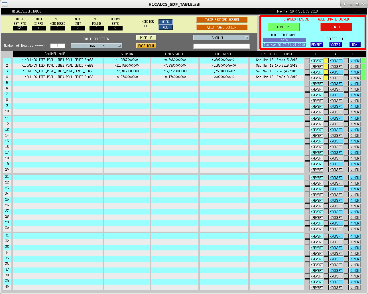
Joe B had told us that we would need to adjust the demod phase for the calibration lines in the front end to get the real time cavity pole (and maybe other factors) correct, related to LLO log 44005 I've added changed the demod phases, setting the demod phase to -360*freq/16384 for each of the pcal demods eg. H1:CAL-CS_TDEP_PCAL_LINE1_PCAL_DEMOD_PHASE
With these phase shifts, the cavity pole is now reading 429 Hz, so this seems good. (To clarify, I didn't mean to say the cavity pole is at it's best possible value, as Peter points out, but that the time depedent factor is reporting a value close to the measured value that Craig posted 47493)
The ideal DARM pole frequency, calculated as in LLO log 41971 and using parameters:
Ts = 0.323Ti = 1.46% (average of the two)re2 = 1 - 35 ppmis frse = 452 Hz.
These changes have beden accepted into the safe.snap of the SDF -- see attached screenshot.
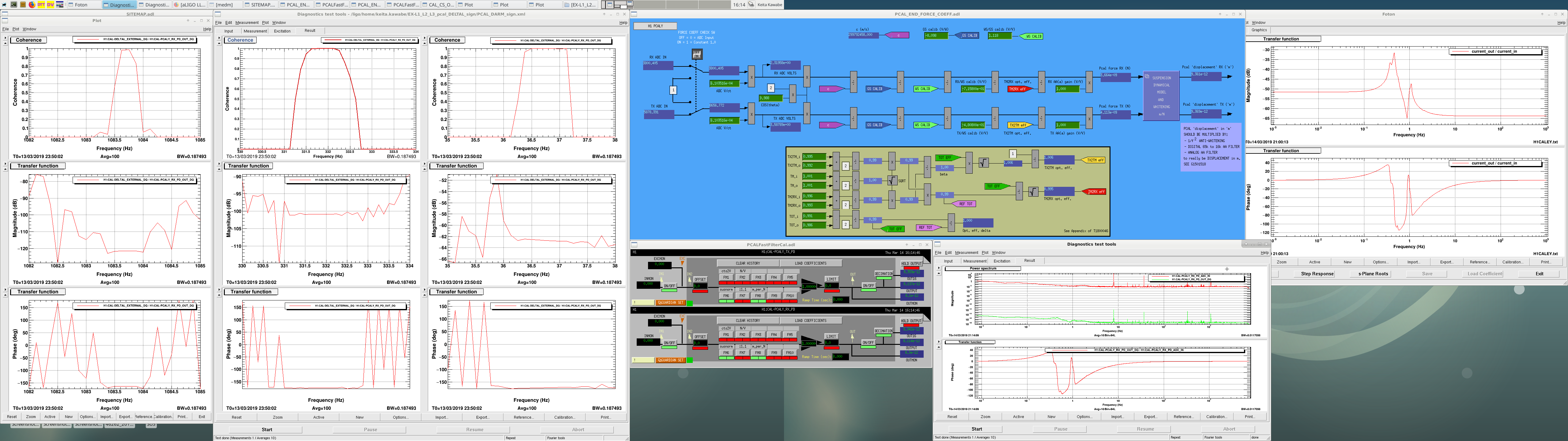
After our finding that overall sign of DELTAL_EXTERNAL was incorrect (alog 47519), we moved on to fix the issue. We ended up changing the sign of sensing path H1:CAL-CS_DARM_ERR_GAIN, and flipped armsign in the actuation path for L1, L2, L3 for EX and EY (H1:CAL-CS_DARM_ANALOG_ETMX_L3 etc. filter FM8).
This is a record of what we did and why, so people can find the information later and blame us if needed.
1. We decided that both the actuation path and sensing path need sign flip.
We had three supporting evidences for this.
One is a clear indication that ESD path sign is wrong (see 2. below).
One is the above-mentioned alog itself, especially this plot. The phase flip is observed at 36Hz where DELTAL_EXTERNAL is somewhat actuation-dominant (DARM UGF is 40-60Hz) and 1083Hz where DELTAL_EXTERNAL is sensing-dominant. Since the measurement showed the wrong phase at 1083Hz the sensing sign is wrong. If the actuation sign were OK the measurement wouldn't have shown 180 degrees phase at 36Hz.
One is the comparison of DARM OLTF between the measured and the model Sheila made from the calibration model G=A*C*D. Measured OLTF is actually -G. To make the model align with the measured, she made a sign flip in the model, i.e. -A*C*D. There's no ambiguity in D (it's just digital filters), so this means that relative phase between A and C is good.
All of these three observations mean that both A and C needed sign flip. Question is, where to flip the sign?
2. ESD sign seemed incorrect on its own.
Last stage of the actuation model seemed to have a wrong sign. This was first found by just looking at the CS_DARM_ANALOG_ETMX_L3 filter that represents the transfer function from DAC output counts to deltaL=Xarm-Yarm.
If you look at the first attachment, DC phase is 180 degrees, meaning when DAC outputs positive voltage, Xarm becomes shorter. This is not true when the bias voltage is negative.
Attractive force = alpha*(Vb-Vs)^2 where Vb is the bias, Vs the signal voltage and alpha a positive constant.
This force pulls the test mass towards the reaction mass. When Vb is negative, more positive Vs means larger force, which pulls more toward the reaction mass, thus Xarm becomes larger, thus deltaL becomes larger. The DC phase should be zero.
Note that if the bias is positive, the polarity of the ESDs should be the same as OSEMs in that a more positive output from DRIVEALIGN into ESDOUTF (i.e. more positive Vs) will pull the mirror less toward ERM to make Xarm shorter, just like a more positive output from DRIVEALIGN into COILOUTF will push the mirror more away from ERM to make Xarm shorter.
3. Further actuation investigation.
Looking at Evan's alog and T1800456, there are explicit signs provided in the CS_DARM_ANALOG_ETMX_L3 to cope with this kind of stuff named biassign, actsign and armsign. There are actsign and armsign for OSEM paths.
biassign takes care of the sign of bias. biassign=-1 means negative bias.
actsign is intended to be used to absorb the difference between ESD and OSEMs, but as I noted in the previous section, OSEMs and ESDs share the same polarity if the bias is positive. Therefore we didn't agree with Evan's alog statement 2), i.e.
"since the ESD is exerts a pulling force, then FM7--"actsign"--gets a value of -1. All ESDs will have actsign=-1 while pushing actuators (OSEMs) get a value of +1. "
as far as bias sign is handled separately. If you set actsign of OSEMs as +1, ESDs should be +1 too. In that case, it is convenient to think of this as the sign between the input into COILOUTF and the local coordinate XLC (where XLC axis is pointing toward the corner station). Positive input in COILOUTF pushes the mirror away from reaction mass so the mirror moves in +XLC direction. Same thing for ESD with positive bias.
armsign is intended for absorbing the difference between X and Y actuation. It's convenient to think of this as absorbing the sign difference between the local coordinate XLC and dL=Xarm-Yarm. Note that Xarm length and XLC are opposite in sign. Therefore armsign for X arm is dL/XLC=Xarm/XLC=-1. In the same manner armsign for Y arm is 1. I'm not sure if that's the intent of this by the calibration group, but Evan set this bit as -1 for ESDX and that agrees with this interpretation.
We looked at these as of today and right after Evan's alog. What looks good based on the interpretation above is colored in blue, bad in red.
| Today | Evan | ||
| EX L3 | biassign | -1 | -1 |
| actsign | 1 | -1 | |
| armsign | 1 | -1 | |
| EX L2 | actsign | 1 | 1 |
| armsign | 1 | 1 | |
| EX L1 | actsign | 1 | 1 |
| armsign | 1 | 1 |
It seems that somebody decided at some point that actsign and armsign of ESD should be the same as OSEMs after Evan wrote his alog.
Since we concluded that all actuation sign needs to be flipped in Section 1. above, we decided to flip armsign of all three stages. We checked the armsign of EY, they were all -1, so we flipped that too.
These are in FM8 of H1:CAL-CS_DARM_ANALOG_ETMX_L3, L2, L1, H1:CAL-CS_DARM_ANALOG_ETMY_L3, L2, L1.
(Alternative interpretation of the designers' intent about signs is that actsign is the relative sign between input into COUIOUTF and arm length, and that armsign is the relative sign between dL and arm length. In that case all actsigns are -1, all armsign for X are +1, all armsign for Y are -1. It was hard to tell which was intended, we didn't take this interpretation because Evan was very clear about the actsign of OSEMs.)
4. Sensing sign
There was only one apparent place that could be conveniently used to flip the sign of sensing, which is H1:CAL-CS_DARM_ERR_GAIN. We flipped this from 1 to -1. You might want to move it to filter bank.
5. Summary
"before change" is the same as "today" in the previous table.
| Change we have done today | Change we'd have made if we adopted an alternative interpretation | Today before change | ||
| EX L3 | biassign | -1 | -1 | -1 |
| actsign | 1 | -1 | 1 | |
| armsign | -1 | 1 | 1 | |
| EX L2 | actsign | 1 | -1 | 1 |
| armsign | -1 | 1 | 1 | |
| EX L1 | actsign | 1 | -1 | 1 |
| armsign | -1 | 1 | 1 | |
| EY L3 | biassign | -1 | -1 | -1 |
| actsign | 1 | -1 | 1 | |
| armsign | 1 | -1 | -1 | |
| EY L2 | actsign | 1 | -1 | 1 |
| armsign | 1 | -1 | -1 | |
| EY L1 | actsign | 1 | -1 | 1 |
| armsign | 1 | -1 | -1 | |
| H1:CAL-CS_DARM_ERR_GAIN | -1 | -1 | 1 |
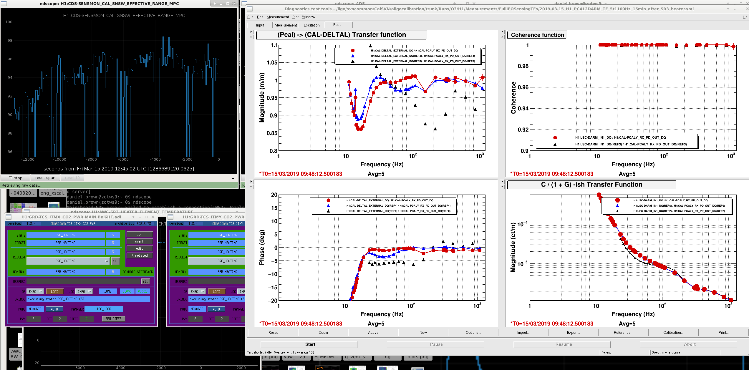
This change in sign seems to have affected CW injections. I'm seeing degraded recovery from the handful of injections loud enough to be recovered in one day's worth of data. The injections are now, I believe, 180 degrees out of phase w.r.t. the intended phases. Do we need to insert an updated actuation function from the calibration team? A poor man's solution: I can make my own by flipping the sign on what I have now, but I don't want to do something rash if this sign issue isn't fully understood and settled. Thanks.