Displaying reports 42621-42640 of 88668.Go to page Start 2128 2129 2130 2131 2132 2133 2134 2135 2136 End
Reports until 15:06, Tuesday 12 March 2019
LHO VE (VE)
gerardo.moreno@LIGO.ORG - posted 15:06, Tuesday 12 March 2019 (47464)
CP3 <--> CP4 Gauge Swap

A vendor reported an issue with one of the mechanical gauges at CP3, the problem was verified and the quick solution was to swap gauges with CP4 (this tank is not being used at the moment).

First I cleaned the large 6 inch dial gauge, debris and dead bugs were removed, but after some water revealed a leak on the 2.5 inch gauge threaded connection I opted to swap the entire assembly.  The leak might turn out to be a source of noise on our read back channel.

The gauge pair from CP4 was removed and installed on CP3, all connections were torqued and valves returned to their normal position, had to close the liquid side shut-off valve for both tanks.  The gauge pair removed from CP3 was installed on CP4.  No issues were encountered during procedure, aside from the snow and the leak.

Work done under WP#8124.


LHO General (DCS)
jonathan.hanks@LIGO.ORG - posted 14:32, Tuesday 12 March 2019 (47467)
Upgraded the OS of the DMT login box (h1dmtlogin)

The OS of the DMT login box h1dmtlogin was upgraded today to Debian 9.  This was done under WP 8116.

H1 CDS
david.barker@LIGO.ORG - posted 14:00, Tuesday 12 March 2019 - last comment - 15:56, Tuesday 12 March 2019(47465)
h1edc install on h1susauxh34 hit a snag, will try again later in the week

Running the new external EDCU model h1edc on h1susauxh34 resulted in a dmesg error:

h1edcepics[896] general protection ip:7f1c80b48ced sp:7fffe66841a0 error:0 in libc-2.12.2.so[7f1c80ae5000+15d000]

Daniel has called a halt to maintenance, so we will work this problem offline.

Details:

The external edcu has been extensively tested with no problems on the DAQ Test Stand all last week, and yesterday I rebuilt x1edc against Rolf's tagged 3.5.0 release. I followed this install and build procedure on H1 this morning:

For each HnEDCU_{name}.ini file in the DAQ master, in its userapps location I created an equivalent HnEPICS_{name}.ini file (minus the default header) and created a symbolic link to it from /opt/rtcds/lho/h1/chans/daq/. Also in this directory I created the edcuheader.txt and edcumaster.txt files. 

On h1boot1 I edited the rtsystab file adding h1edc to h1susauxh34. The tested x1edc.mdl model was copied to h1edc.mdl with the appropriate X1->H1 conversions. The model was compiled and install-nort'ed.

When I ran h1edc, it emptied the H1EDC.ini file but did not populate it with the full channel list. The channel count PVs briefly existed with zero values before the code crashed.

Comments related to this report
david.barker@LIGO.ORG - 14:02, Tuesday 12 March 2019 (47466)

I had queued up the DAQ changes needed for the extenal EDCU:

  • stop running "epics dcu" on h1dc0
  • remove all EDCU ini files from master, replace with H1EDC.ini

These changes have been reverted out of the DAQ for now.

david.barker@LIGO.ORG - 15:36, Tuesday 12 March 2019 (47469)

Jonathan, Dave:

We found the error, I had introduced a bad carriage return in the edcumaster.txt file, and I remembered Keith alogging that any spaces in this file is bad. I fixed the file and restarted h1edc. Initially it was not connecting to the 3,404 guardian channels, and when guardian was started h1edc connected to the full list of 40,069 epics channels.

We will schedule a DAQ restart to switch from internal to external EDCU at the next target-of-opportunity.

jonathan.hanks@LIGO.ORG - 15:56, Tuesday 12 March 2019 (47472)

I tracked the crash point down in the code.  See CDS bug 1136.

H1 SUS (ISC)
filiberto.clara@LIGO.ORG - posted 13:51, Tuesday 12 March 2019 (47463)
ESD Grounding at End-Y

WP 8120

ESD electronics grounding was isolated and a single ground connection to beam tube was made. Same work previously done at EX, alog 47308.

1. Removed rack ground to all power supplies
2. Cable SUS-ETMX-90 had pin 8 removed
3. Installed shelving and nylon screws to both the LN ESD driver and HV UK driver
4. Junction box front panel had to be removed and reattached to isolate the SHV connectors from ground
5. With all power and signal cables connected, verified electronics were isolated. Ran single cable to beamtube for reference ground.

F. Clara, P. King, R. McCarthy

H1 ISC
richard.mccarthy@LIGO.ORG - posted 13:06, Tuesday 12 March 2019 (47460)
EX safety system

While trouble shooting the glitches on the PCAL temperature sensor a two connectors at EX were inadvertently swapped.  This caused a problem when the pcal lid was opened and the ALS table door was opened. The system thought it was in an unsafe condition and tripped off the lasers.  I have fixed the wiring issue that existed at end X only.  Y-end was not a problem.

H1 ISC
daniel.sigg@LIGO.ORG - posted 12:56, Tuesday 12 March 2019 - last comment - 18:47, Tuesday 12 March 2019(47459)
Common mode board readbacks

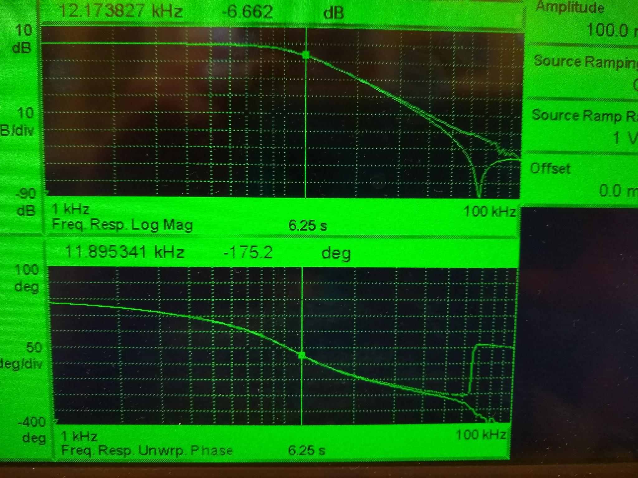
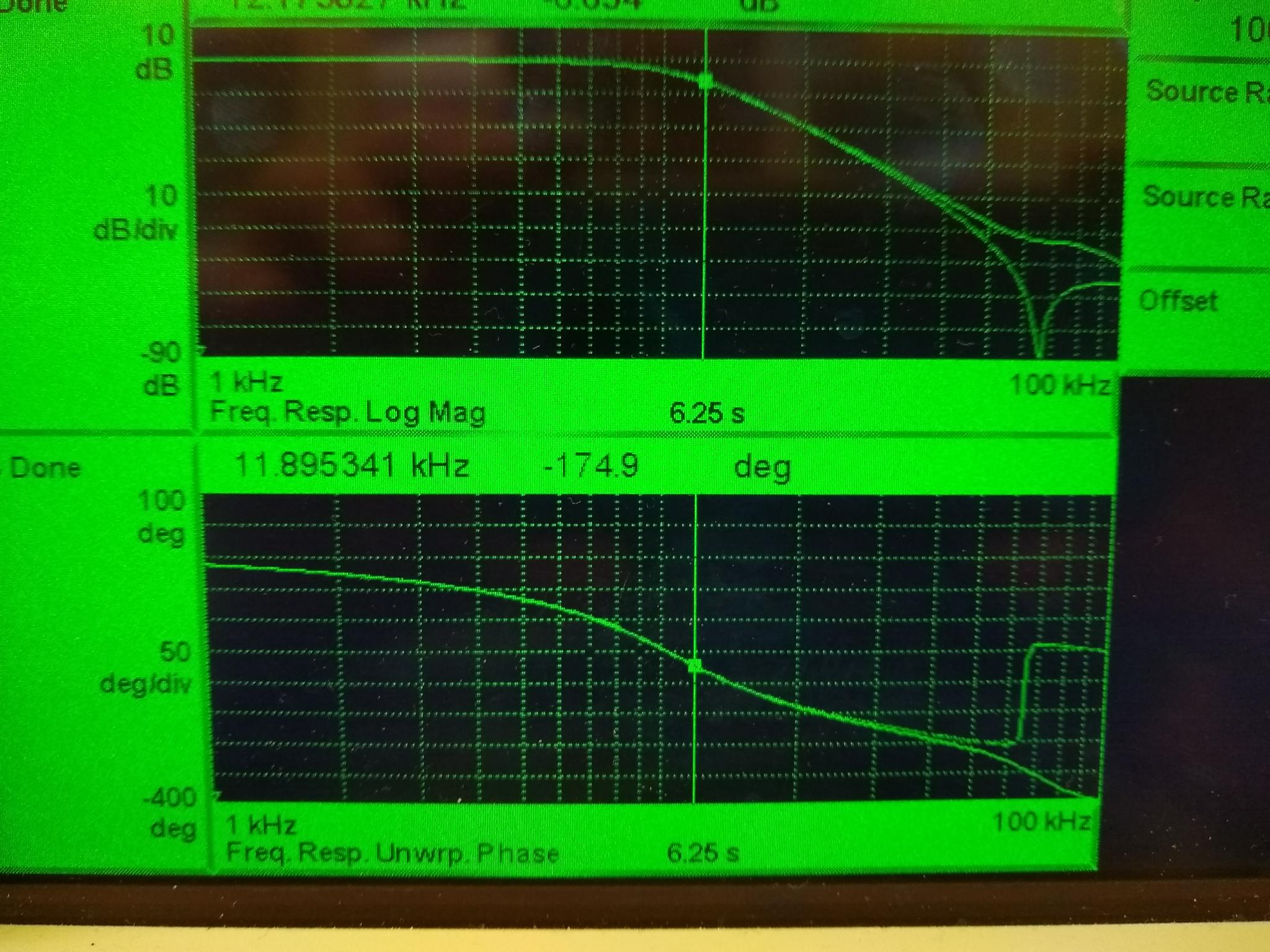
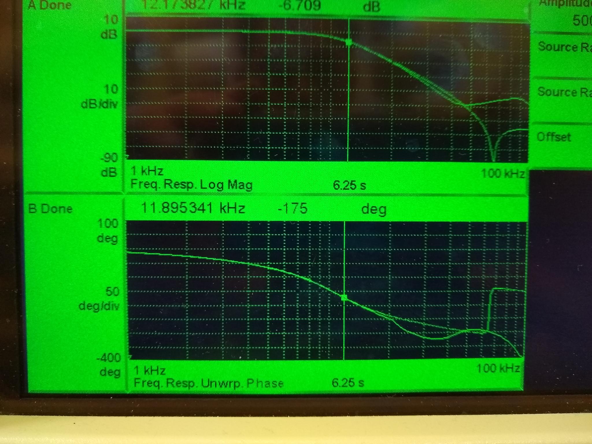
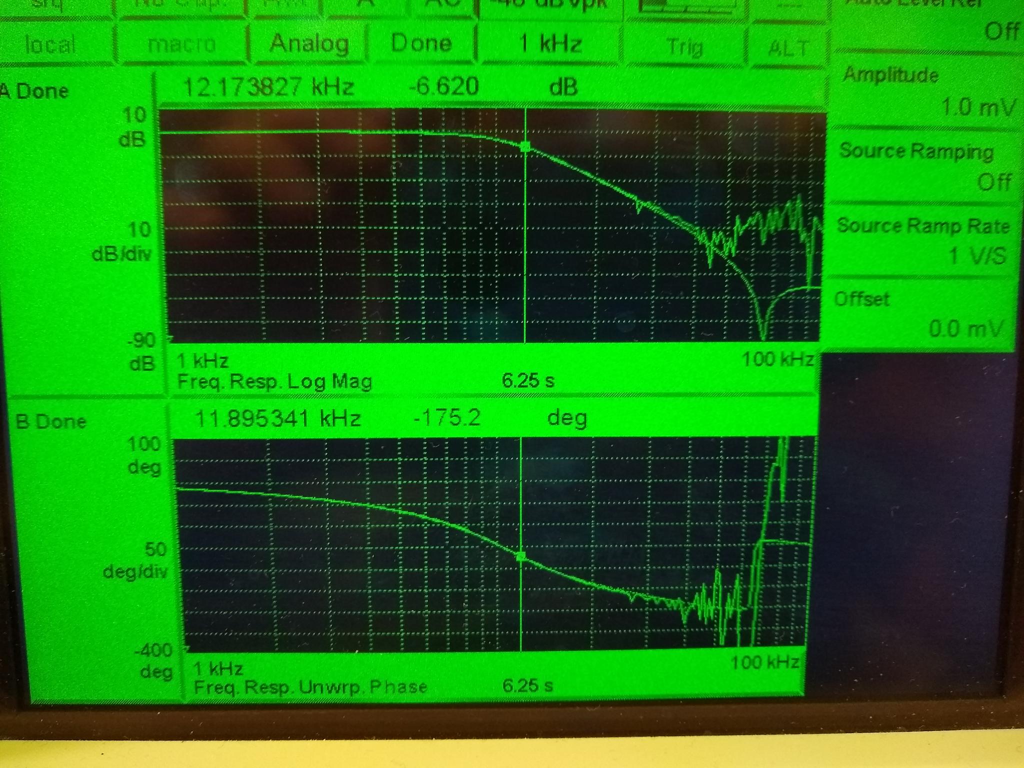
Opening up the AA chassis (S/N S1102788) we confirmed that the AA boards D070081 (chn 16-23 S/N S1202203; chn 24-31 S/N S1202202) have AD8622 stuffed. On channels  20-27 all of them (input and output) were replaced by ADA4075-2ARZ. This incudes the channels for the LSC_REFL_SERVO readbacks, the IMC-REFL_SERVO readbacks and the SQZ-CLF_REFL_RF6 readbacks. Attached are some measured transfer functions for a channel with the ADA4075-2 (reference trace with notch) and for a channel with the AD8622 (no notch). Varying the drive voltage from 1mV to 5V made no difference for the ADA4075-2, For the AD8622, one can clearly see that it cannot drive fast enough and at frequencies around the notch it looks anything but a notch.

Plots: AD8622 transfer function for 5V, 1V, 100mV, 10mV and 1mV drive compared against the ADA4075-2.

Images attached to this report
Comments related to this report
daniel.sigg@LIGO.ORG - 18:12, Tuesday 12 March 2019 (47482)

Repeating the measurements done in alog 47345, we find significant improvements. We now have good coherence between CTRL and SLOW for most of the frequency range. Due to the pole at 500 Hz the SLOW readback runs into quantization noise above 15 kHz. The ERR signal readback also has much better coherence. Between 10 and 100 Hz it seems limited by the  voltage noise of the first boost stage.

The line at ~14 kHz dominates the rms.

Non-image files attached to this comment
daniel.sigg@LIGO.ORG - 18:24, Tuesday 12 March 2019 (47484)

And here is the low frequency version.

Non-image files attached to this comment
daniel.sigg@LIGO.ORG - 18:47, Tuesday 12 March 2019 (47485)

Here are the plots for the IMC servo. The faster OpAmps also improved the IMC-F and IMC-L readbacks. The IMC_I readback shows flat noise at a relatively high voltage level. It may be limited by out-of-band noise.

First plot show current readbacks compared to the old ones.

Second plot shows the raw input signals in counts. There seems to be some excess noise between 10 and 50 Hz in IMC-F. Maybe a glitch here since the next plot looks different.

Third plot shows a full bandwidth spectrum. MC-F approaches the quantization noise between 1 and 20 Hz.

Non-image files attached to this comment
H1 ISC (ISC)
keita.kawabe@LIGO.ORG - posted 11:53, Tuesday 12 March 2019 - last comment - 15:40, Tuesday 12 March 2019(47445)
Weak IMC-COMM VCO whistle observed, DIFF and COMM were turned off (we still have IMC-SQZ)

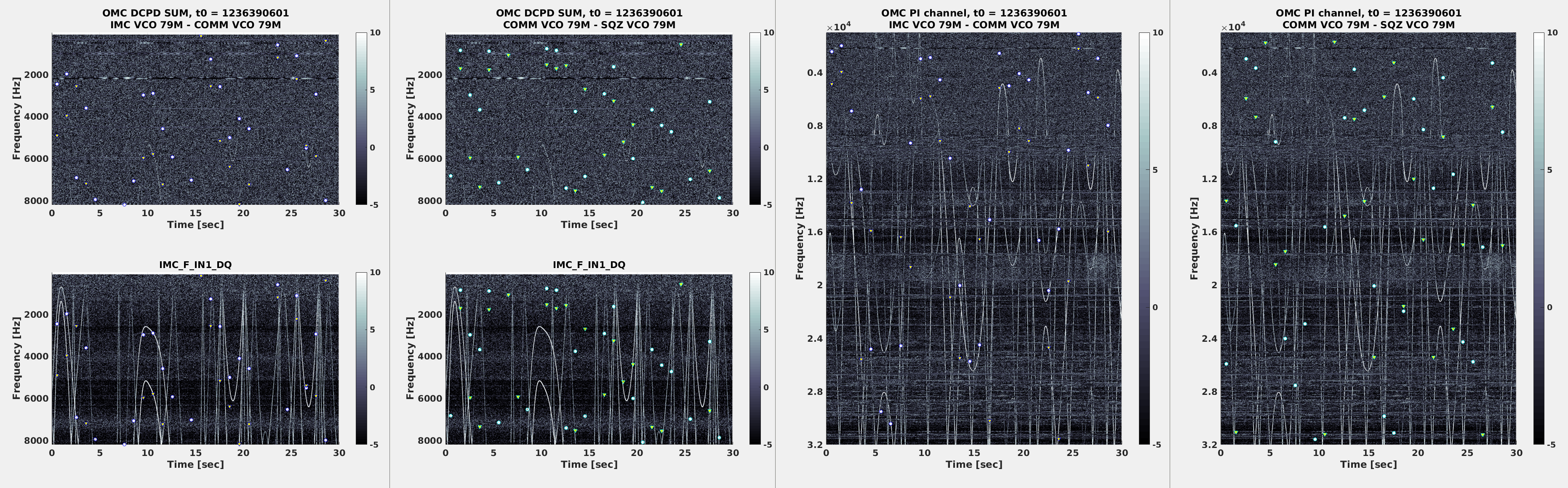
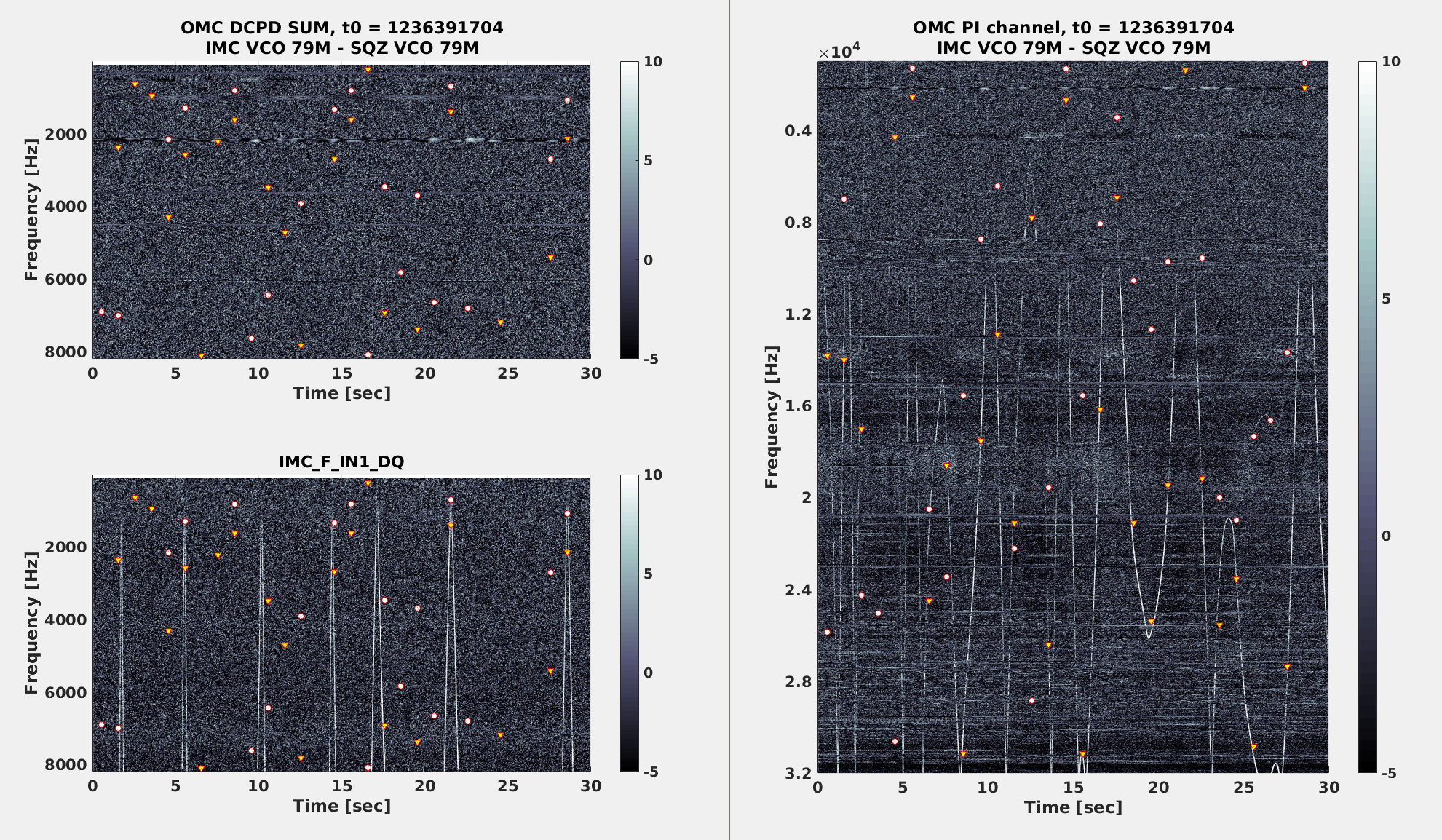
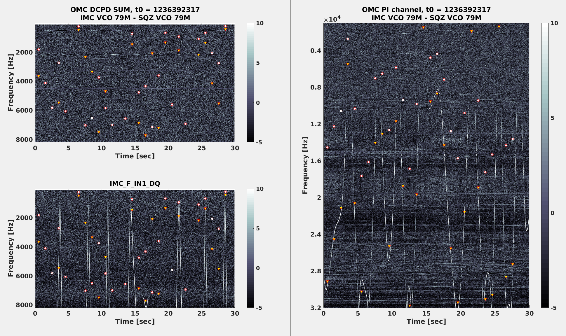
In the first lock of this afternoon I saw no IMC-DIFF but at least three weak IMC-COMM arches (first attached, left).

On her way to HAM6 AnaMaria also went to the ISC rack and turned off both COMM and DIFF VCO.

After that, the only clear wondering line in OMC PI channel is the second harmonics of IMC-SQZ (2nd and 3rd attachment right, triangles). It's hard to say but DCPD might be somewhat better than before turning off DIFF and COMM.

During this time SQZ guardian was in PREP_IFO_SQZ state.

Update:

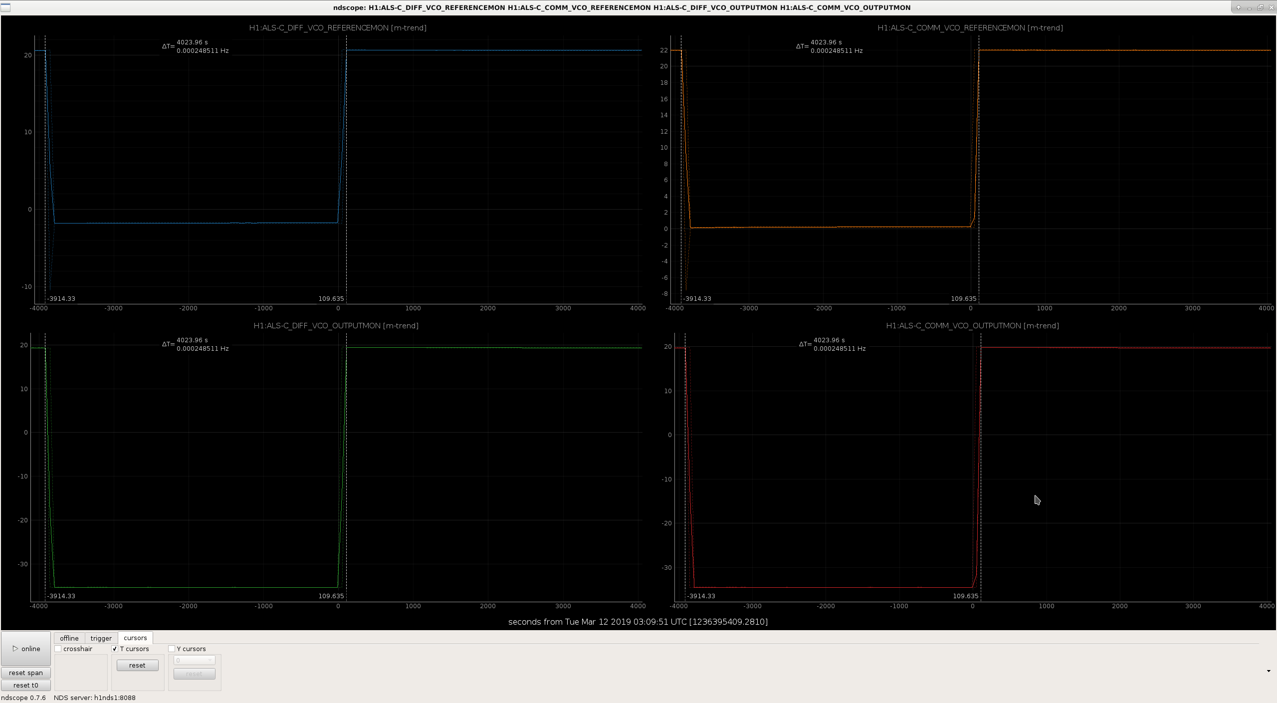
VCOs were turned back on about an hour later. The time the VCOs were OFF is from about [-3914, 110]+1236395409 GPS time.

Images attached to this report
Comments related to this report
daniel.sigg@LIGO.ORG - 15:40, Tuesday 12 March 2019 (47470)

Looking back at O2, we parked the DIFF and COM VCOs at 78.786600 MHz and 78.7990 MHz, respectively, while the IMC VCO was running around 79.135 MHz.

During the last lock, we parked the DIFF and COM VCOs at 78.786600 MHz and 78.7990 MHz, respectively, while the IMC VCO was running around 78.786 MHz. The IMC VCO frequency was changed around 3/2/2019. No obvious alog.

The parking positions are unchanged, whereas the IMC VCO has moved down in frequency on top of the parking positions. This is bad! The IMC VCO needs to move ~350 kHz up in frequency.

Set the IMC-VCO_TUNEOFS to -1.7 V which puts the frequency back to 79.2 MHz.

LHO VE
kyle.ryan@LIGO.ORG - posted 11:38, Tuesday 12 March 2019 (47457)
Chilled water booster pump repair @ Yend completed

Pressure tested -> Shaft seal (original problem) and union joints leak tight -> good!

Approximately 1 gallon of water/glycol was spilled and removed from the system as the result of removing the pump last week.  I noted when adding the make-up glycol today that the closed-loop pressure was only 15 psig (historical normal is 30 psig).  I only added enough to bring the closed-loop pressure up to 20 psig as (i assume) the variable speed drive is operating at <60 Hz these days. 

H1 DetChar (DetChar)
keith.riles@LIGO.ORG - posted 08:29, Tuesday 12 March 2019 - last comment - 10:57, Friday 29 March 2019(47450)
Strong 1 Hz comb appearing in H1 DARM after last Tuesday's maintenance
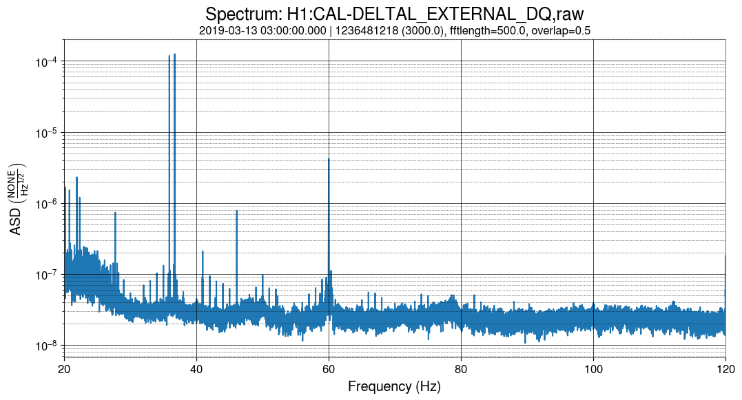
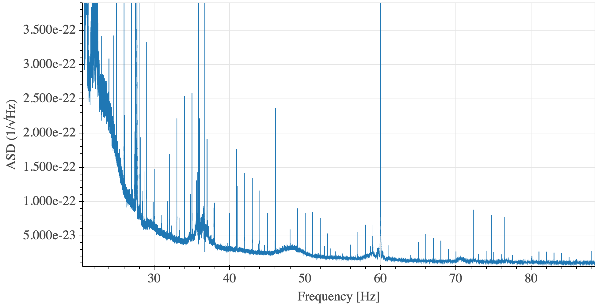
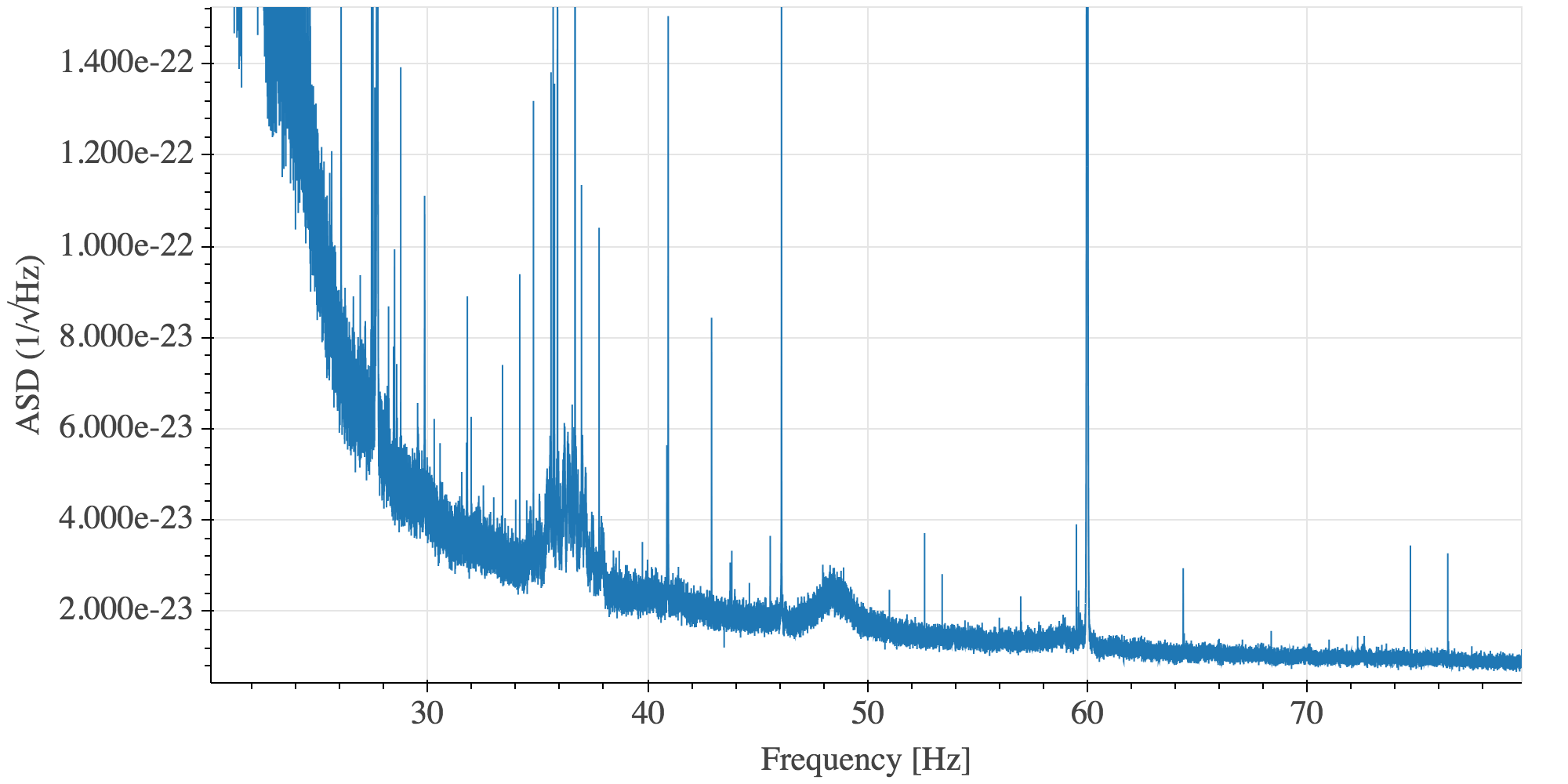
Given that H1 is still in commissioning mode, I hesitate to report on lines that may be due to ongoing work, but I'm seeing a very strong 1-Hz comb in DARM as of last Wednesday, which I suspect is unintended. Below are spectra of 20-120 Hz and its 20-Hz sub-bands from yesterday's data (typical of daily spectra since Wednesday). 

Note that the lines are on exact 1-Hz multiples (to ~0.5 mHz resolution), but they have flat shoulders of O(0.01 Hz) full width. An arbitrary but typical example at 34 Hz is shown.

Also, the amplitudes of the lines do not fall entirely monotonically with frequency. There are clusters of lines with a spacing of roughly 7-8 Hz.

Any ideas on what changed, perhaps during the last Tuesday maintenance? 
Images attached to this report
Comments related to this report
ansel.neunzert@LIGO.ORG - 10:19, Tuesday 12 March 2019 (47454)

Additional clue: there are small but noticeable changes in comb strength in a couple magnetometer channels at EX, in the same time frame. I'm not seeing anything similar in EY or CS mags. (The 1-Hz comb is present in many magnetometers; it's the change points that seems to be unique to EX.)

daniel.vander-hyde@LIGO.ORG - 11:59, Tuesday 12 March 2019 (47455)

Hey all, 

This looks similar to what we have seen in the past from the hartmann wavefront sensor cameras. It seems like we solved the issue by changing the camera power supplies.  We can double check this by changing the HWS sync frequency at low noise and provide you with a gps time. 

sheila.dwyer@LIGO.ORG - 12:16, Tuesday 12 March 2019 (47458)

Sheila, Anamaria

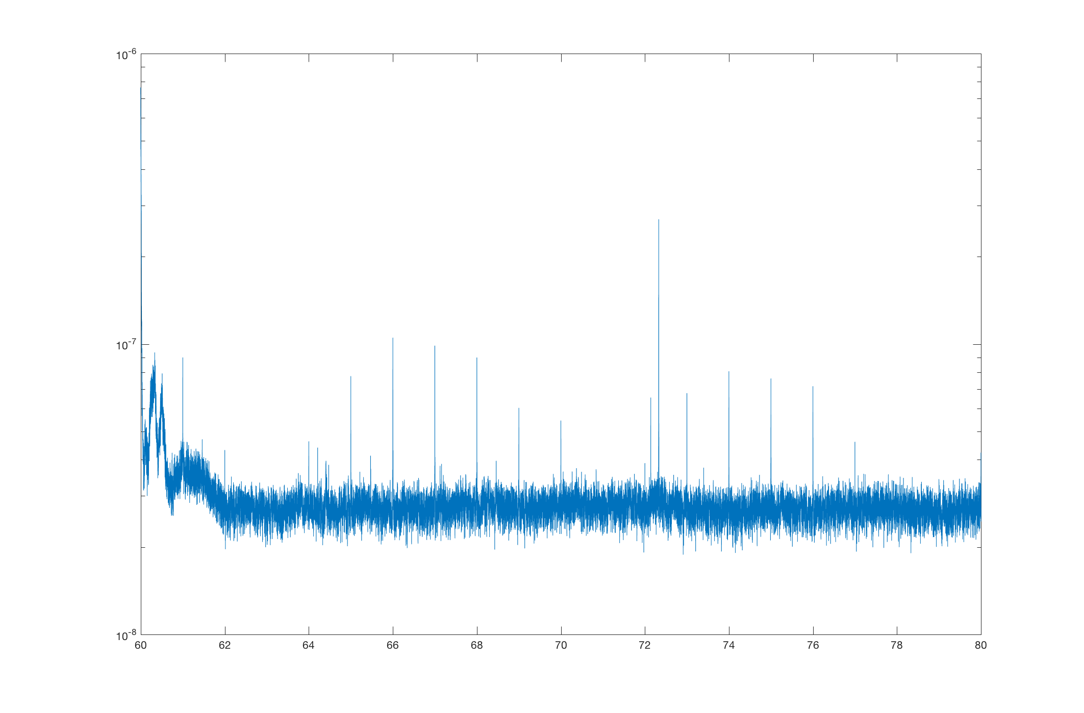
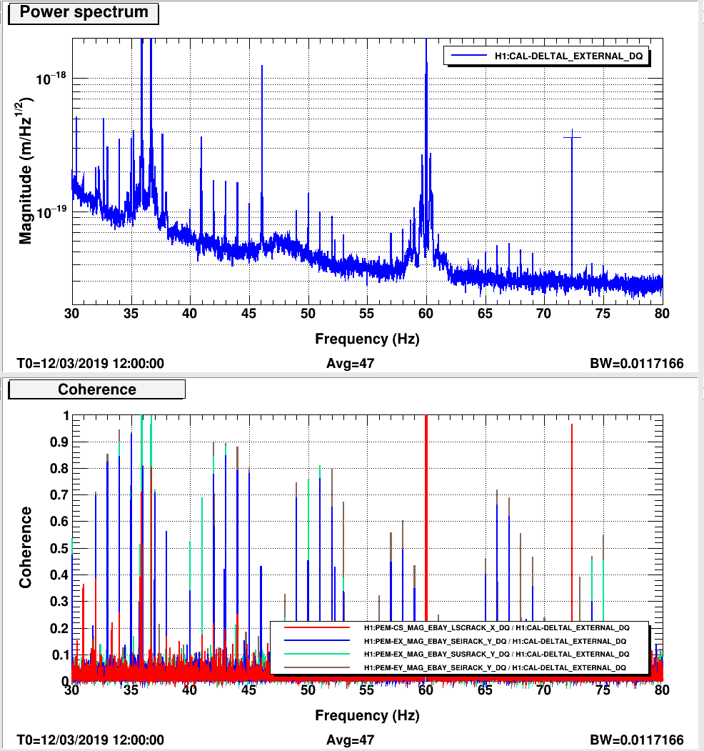
The first thing that comes to mind from last Tuesday is a change to the ESD driver grounding at EX (47308), which did reduce some coherence between EX magnetometers and DARM (47323)  At first it looked like this work last tuesday removed a line at 73 Hz from DARM, although looking at the summary page you can see that this line has been coming and going and was at 72.5 Hz yesterday. summary page

andrew.lundgren@LIGO.ORG - 13:07, Tuesday 12 March 2019 (47461)DetChar
It's probably not the HWS because those were always showing up a few tenths of a percent below their sync frequency, so if this comb is within half a mHz it's too accurate.
ansel.neunzert@LIGO.ORG - 13:18, Tuesday 12 March 2019 (47462)

Ok, I'm posting more detail on what I'm seeing in the magnetometers, in case it helps to pin this down. I've checked for any obvious/clear change points, and also compared whether the shape of the comb is similar to what's observed in DARM (same pattern of variation in peak heights). In summary, SEIRACK and SUSRACK magnetometers at EX are particularly notable.

Also, the comb does appear to be precisely on 1 Hz, unlike the HWS comb.


Detailed magnetometer report:

[Corner station]
H1:PEM-CS_MAG_EBAY_LSCRACK_*_DQ: no apparent change; comb shape dissimilar from what is observed in DARM
H1:PEM-CS_MAG_EBAY_SUSRACK_*_DQ: no apparent change; comb shape dissimilar
H1:PEM-CS_MAG_LVEA_VERTEX_*_DQ: comb not really present

[End X]
H1:PEM-EX_MAG_EBAY_SEIRACK_X_DQ: changed (decrease); comb shape similar
H1:PEM-EX_MAG_EBAY_SEIRACK_Y_DQ: no apparent change; comb shape similar
H1:PEM-EX_MAG_EBAY_SEIRACK_Z_DQ: changed (increase); comb shape similar (?)

H1:PEM-EX_MAG_EBAY_SUSRACK_X_DQ: changed (increase); comb shape similar
H1:PEM-EX_MAG_EBAY_SUSRACK_Y_DQ: no apparent change; comb shape similar
H1:PEM-EX_MAG_EBAY_SUSRACK_Z_DQ: changed (decrease); comb shape similar (?)

H1:PEM-EX_MAG_VEA_FLOOR_*_DQ: comb not really present, but neither is anything else. These channels look way too clean; there might be an issue.

[End Y]
H1:PEM-EY_MAG_EBAY_SEIRACK_*_DQ: no apparent change; comb shape similar
H1:PEM-EY_MAG_EBAY_SUSRACK_*_DQ: no apparent change; comb shape similar
H1:PEM-EY_MAG_VEA_FLOOR_*_DQ: no apparent change; comb shape similar (?)

anamaria.effler@LIGO.ORG - 16:38, Tuesday 12 March 2019 (47473)

Robert, Anamaria

Even with just 0.01 Hz resolution, there is large coherence between various magnetometers in the EBAYs and DARM. Indeed this was not the case before last Tuesday.

Separately, the 72.5 Hz that appeared in the last two days is coherent with the corner EBAY magnetometer in the ISC rack. We think it's a real peak because if the sensor were picking up DARM the large calibration lines at 35ish Hz would show better coherence. Though it does not appear to be there this morning, so not completely clear what's going on.

Images attached to this comment
daniel.brown@LIGO.ORG - 17:00, Tuesday 12 March 2019 (47475)

Danny and I had a 72.33 Hz line driving some frequency noise over the weekend during some TCS tests. We also had lines at 3.25kHz, 4.5kHz and a bunch around 23-25Hz.

daniel.vander-hyde@LIGO.ORG - 23:47, Tuesday 12 March 2019 (47489)DetChar

Shifted ETMX HWS sync frequency from 1 Hz to 5 Hz starting at 1236485181 and shifting it back to 1 Hz at 1236494796.

daniel.sigg@LIGO.ORG - 15:41, Wednesday 13 March 2019 (47504)

What about the GPS clocks that got turned on last Tuesday?

keith.riles@LIGO.ORG - 17:55, Wednesday 13 March 2019 (47507)DetChar
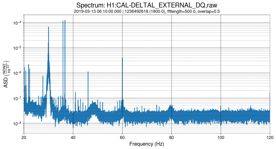
I had trouble finding a lot of clean DARM data during the period when the HWS frequency was changed, but what I found suggested the 1-Hz was still strong. Figure 1 is from when the HWS frequency was normal. Figure is from when it was changed.

Images attached to this comment
pep.covas@LIGO.ORG - 11:32, Tuesday 26 March 2019 (47884)

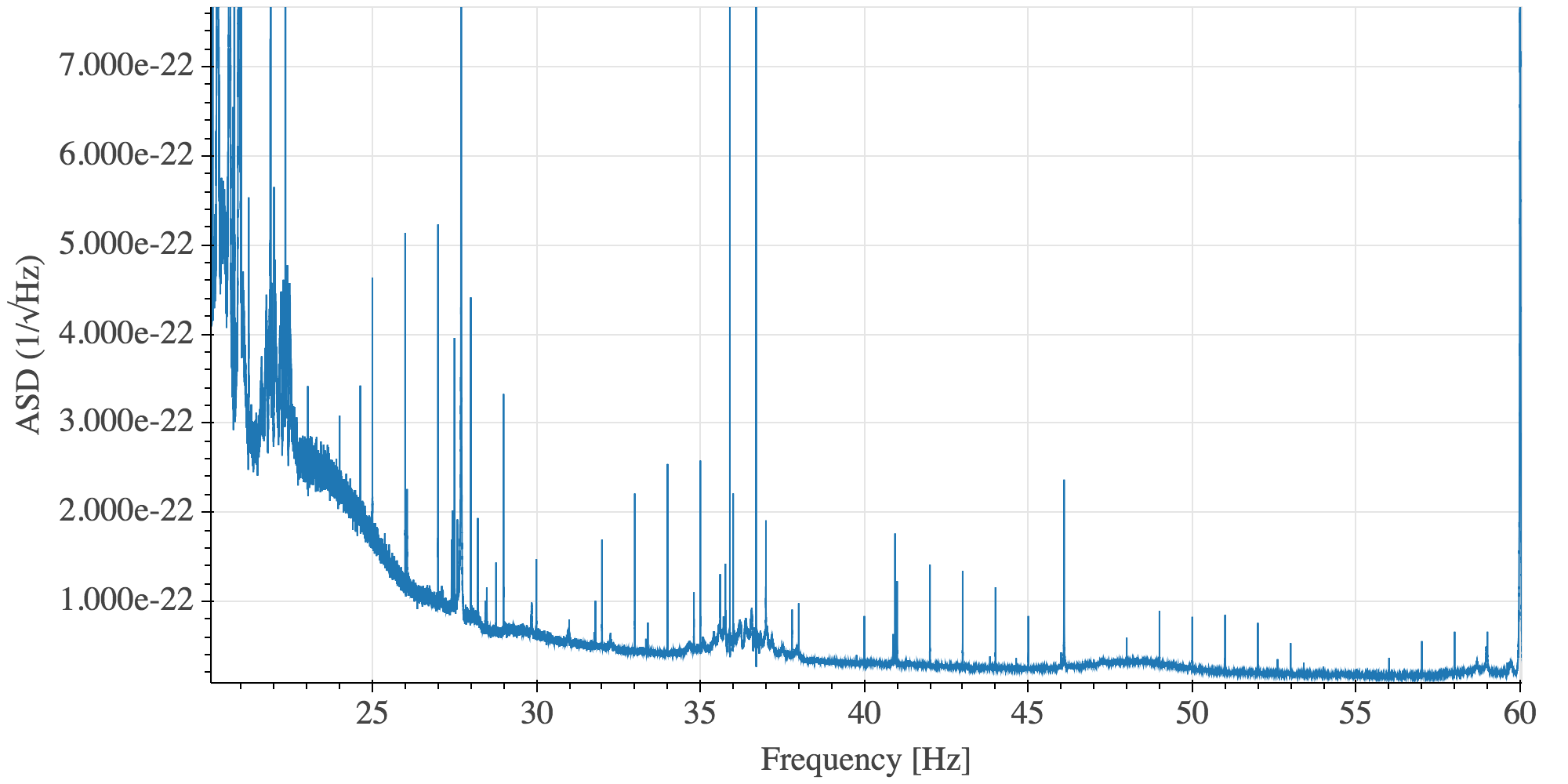
The 1 Hz comb is still present in data from the third week of ER14, see first attached plot. There is also a very bad 0.8 Hz comb visible between 420 and 500 Hz, see second plot.

Images attached to this comment
ansel.neunzert@LIGO.ORG - 13:25, Wednesday 27 March 2019 (47932)

The 0.8 Hz comb Pep noted is a complicated structure, but it has some symmetrical features which are centered on the 516.78 Hz line. Keith tells me this is an EX violin mode (alog 47650, alog 47179).  A plot showing data from March 25 is attached.

Images attached to this comment
pep.covas@LIGO.ORG - 10:03, Friday 29 March 2019 (48032)

It seems that the work reported in https://alog.ligo-wa.caltech.edu/aLOG/index.php?callRep=47766 has made the 1 Hz comb disappear.

The first attached plot shows the spectra before this change, and the second one the spectra after this change.

On the other side, the lines and 0.8 Hz comb around the ~500 Hz violin modes are still there.

Images attached to this comment
H1 General
jeffrey.bartlett@LIGO.ORG - posted 08:14, Tuesday 12 March 2019 - last comment - 09:46, Tuesday 12 March 2019(47451)
Ops Day Shift Summary

Ops Shift Transition: 03/12/2019, Day Shift 15:00 – 23:00 (08:00 -16:00) - UTC (PT)

State of H1: Locked at NLN
Intent Bit: Commissioning
Weather: A cold front is moving through the area this morning bringing snow, sleet, and icy rain. Temperatures are hovering around freezing. The front is forecast to move east around noon and be replaced with winds gusting into the 20s, overcast with temps rising into the 40s.   
Primary 0.03 – 0.1Hz: 0.07um/s
Secondary 0.1 – 0.3Hz: 0.5mu/s
Outgoing Operator: N/A
Quick Summary: IFO remains locked despite snow blowing, operation of the frontend loader doing snow removal, and HAM1 SIS being tripped. Due to snow and icy conditions work start has been delayed until 11:00. Maintenance may be shortened due to the weather.   
Comments related to this report
jeffrey.bartlett@LIGO.ORG - 09:46, Tuesday 12 March 2019 (47452)
   When I came in at 14:20 (07:20) the IFO was locked at NLN. Despite snow blowing and operation of the frontend loader around OSB, the IFO was noisy but remained locked. At 14:36 (07:36)the HAM1 ISI tripped and the IFO remained locked. The IFO did not lose lock until 15:31. 
H1 ISC (ISC)
georgia.mansell@LIGO.ORG - posted 02:27, Tuesday 12 March 2019 - last comment - 11:20, Tuesday 12 March 2019(47447)
46 Hz line

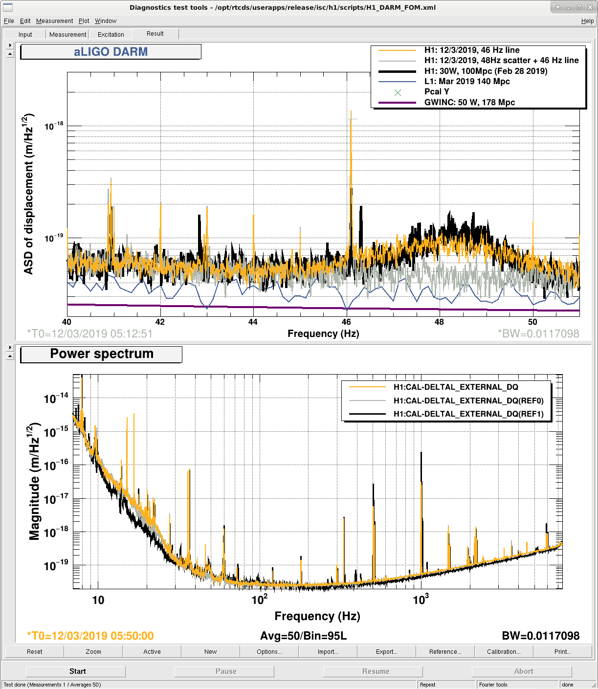
During today's lock we have seen a high narrow peak at 46.1 Hz. This looks to be separate from the wandering 48Hz line (seen as a lump in our DARM spectra).

Bottom plot of attached screenshot is a 0.01 Hz resolution DARM spectrum. The top plot is zoomed into the 46 Hz region: black is a reference from Feb 28, grey and yellow are from two points during today's lock, with low and high ~48Hz line activity respectively. The 46 Hz line was also present in our Feb 28, but today it is a factor of ~4 larger for sone reason.


I ran bruco for a quiet time during this lock, but didn't see strong coherence with anything (closest being 0.21 coherence at 46 Hz with LSC-REFL_A_RF45_I_ERR_DQ).


(I had run bruco at a different time, and was excited to see coherence with an end-x sus rack magnetometer, but it turns out there was a glitch in the time window I picked.)

Images attached to this report
Comments related to this report
jenne.driggers@LIGO.ORG - 11:20, Tuesday 12 March 2019 (47456)

This feels reminiscent of the Hartmann wavefront sensor camera refresh rate.  Team TCS is going to look at this as soon as they are finished with their currently-ongoing maintenance tasks.

EDIT: Never mind, Danny looked, and all of the refresh rates are correctly set to be much lower frequency than this.

H1 ISC (ISC)
rich.abbott@LIGO.ORG - posted 21:50, Sunday 03 March 2019 - last comment - 10:23, Tuesday 12 March 2019(47254)
OMC DCPD Whitening Chain Gain Dependent on Input Signal Level
Stefan, Peter, Rich

It was found that the overall DC gain, and the pole-zero location associated with the second filter module of the OMC DCPD Whitening chain, was somehow dependent on input signal level.  A parametric study was done on the OMC DCPD whitening chain for different whitening filter combinations with and without DC offset.  Notes detailing the parametric study are attached to this entry.  

There were two causes of these phenomena:  
1.  Gain Change - As the DC input to the OMC DCPD Whitening amplifier (D1002559 Chassis S1101627) is varied, the DC level causes saturation in some of the DC coupled gain stages.  This saturation causes the normally high-impedance amplifier input to be fairly low due current flowing into the input protection diodes internal to each opamp stage.  This lower input resistance in conjunction with the series resistance of the FET switches produces a voltage divider with a division ratio dependent on signal level.
2.  Pole-Zero Change - The second filter module had an ECR (E1500252) performed that required a 1uF capacitor to be used.  This type of filter function is supposed to be implemented with a plastic film dielectric capacitor, but a ceramic capacitor was used instead.  The piezoelectric nature of ceramic capacitors can result in a capacitance that will change with applied voltage.  This caused the pole-zero location to vary as a function of DC level.  This capacitor was changed to the proper type and the problem went away.

Data (attached) was taken for both OMC DCPD chains by injecting signals into the input of the OMC whitening chassis (DCPD Preamps disconnected), and taking the output differentially from the analog output of the whitening chassis with the ADC cable still attached (to account for any loading effects).  This data was taken with and without a 5V DC offset to verify that there is no longer any effect on the signal path gain.

We note that the above were all small effects, but significant in the world of 1% calibratin uncertainty. The DC gain reduction with a 5 V offset (similar to the offset in NLN operation) was 0.2 dB. The errors in the filter stage with offset were -- phase: 0.6-1 degree at 50 Hz; magnitude: 0.15 dB gain difference between 50 Hz and 200 Hz.
Non-image files attached to this report
Comments related to this report
jeffrey.kissel@LIGO.ORG - 12:55, Monday 04 March 2019 (47271)CAL, ISC
Rich verbally confirms that he and Peter used the measurement setup as described in LHO aLOG 47225 and D1900027, using the coil driver test box as a differential driver. They *did not* gather the test setup's transfer function, however, so this will need to be done in order to analyze the data (attached above, DCPD_Whitening_v2.zip) to the desired precision. Also note that details of the measurement files can be found on the last page of the DCPDWhiteningChanges.pdf attachment.

Also -- I opened (and subsequently closed) FRS Ticket 12453 covering the problem of "changes in frequency response as a result of input signal level" that the solution in this aLOG fixes.

Since this issue will likely impact LLO as well, I've opened up an integration issue,  IIET Ticket 12454, such that the above mentioned change becomes an ECR to be implemented at LLO as well (assuming they have the same problem).
stefan.ballmer@LIGO.ORG - 00:05, Monday 04 March 2019 (47257)

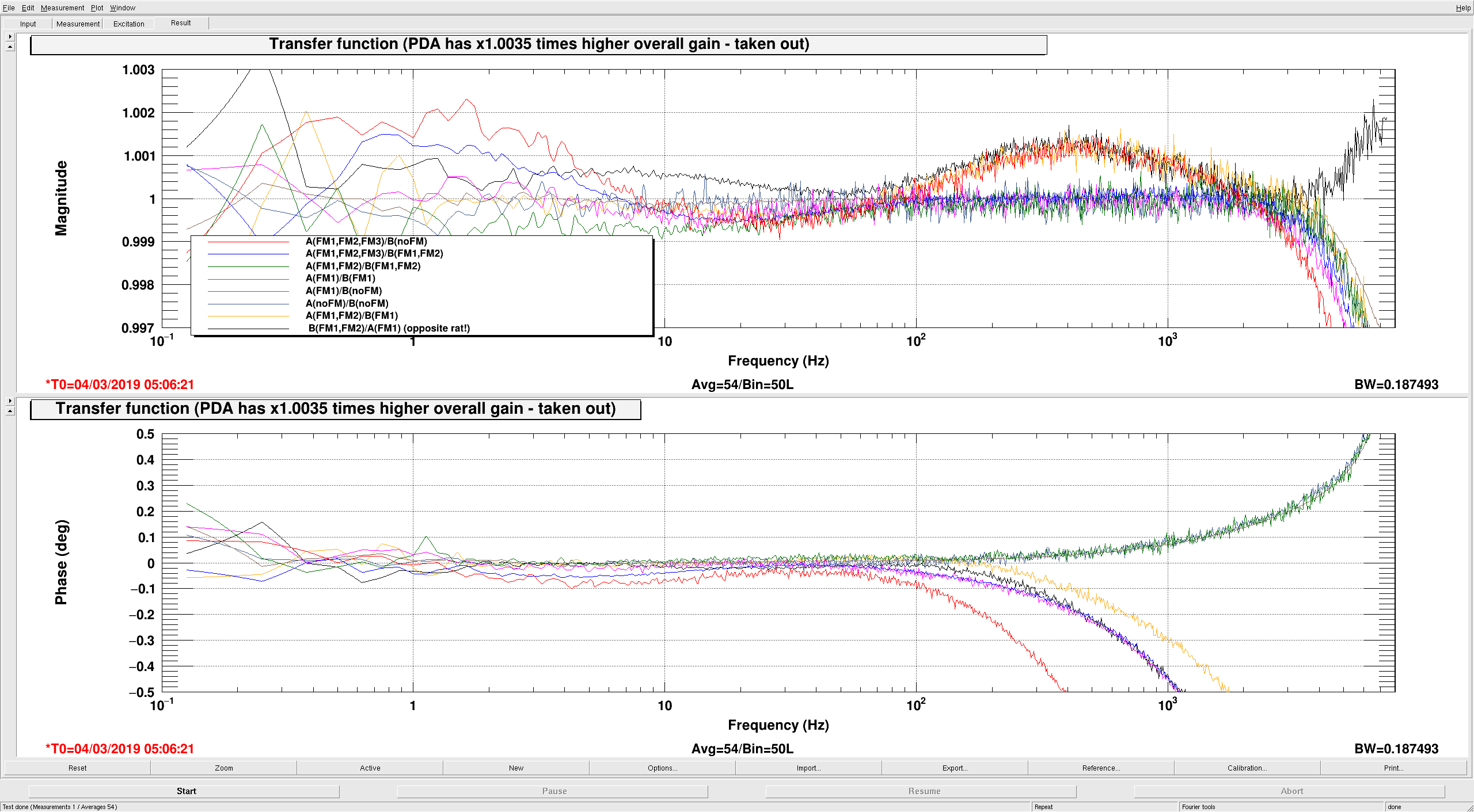
Updated the FM1,FM2,FM3 whitening compensation filters for PDA and PDB.
They are now matched at the +-0.15% level (see plot).
And we verified that they are no loner offset dependent.

Also, to be explicit: We disabled the 12dB, 6dB and 3dB whitening gain steps in both PDA and PDB. The 24dB step is still operational.


The new foton filters are:

PDA:
FM1: zpk([10.44],[0.996],0.9734,"n")
FM2: zpk([49.63],[497.5],-0.9995,"n")
FM3: zpk([10.372],[0.9865],1.002,"n")

PDB:
FM1: zpk([10.160],[0.969],0.975458,"n")
FM2: zpk([49.72],[497.7],-1.0004,"n")
FM3: zpk([10.467],[1.000],.9973,"n")

Using this filter, we injected pink noise into both DCPDs, and plotted the PD ratio in various configurations to verify the filter compensation. Specifically, plotted are:

A(FM1,FM2,FM3)/B(noFM)
A(FM1,FM2,FM3)/B(FM1,FM2)
A(FM1,FM2)/B(FM1,FM2)
A(FM1)/B(FM1)
A(FM1)/B(noFM)
A(noFM)/B(noFM)
A(FM1,FM2)/B(FM1)
B(FM1,FM2)/A(FM1) (opposite rat!)

The xml file with the data in the plot is in /ligo/home/controls/sballmer/20190303/DCPDfinal.xml

Finally, we still will have to re-match the photo diode light levels in lock (alog 47217).


Images attached to this comment
stefan.ballmer@LIGO.ORG - 10:24, Monday 04 March 2019 (47264)

All this was done to fix the problem identified in alog 47247.

stefan.ballmer@LIGO.ORG - 17:26, Monday 04 March 2019 (47280)

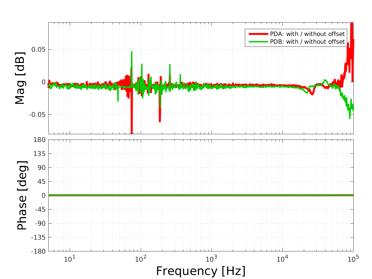
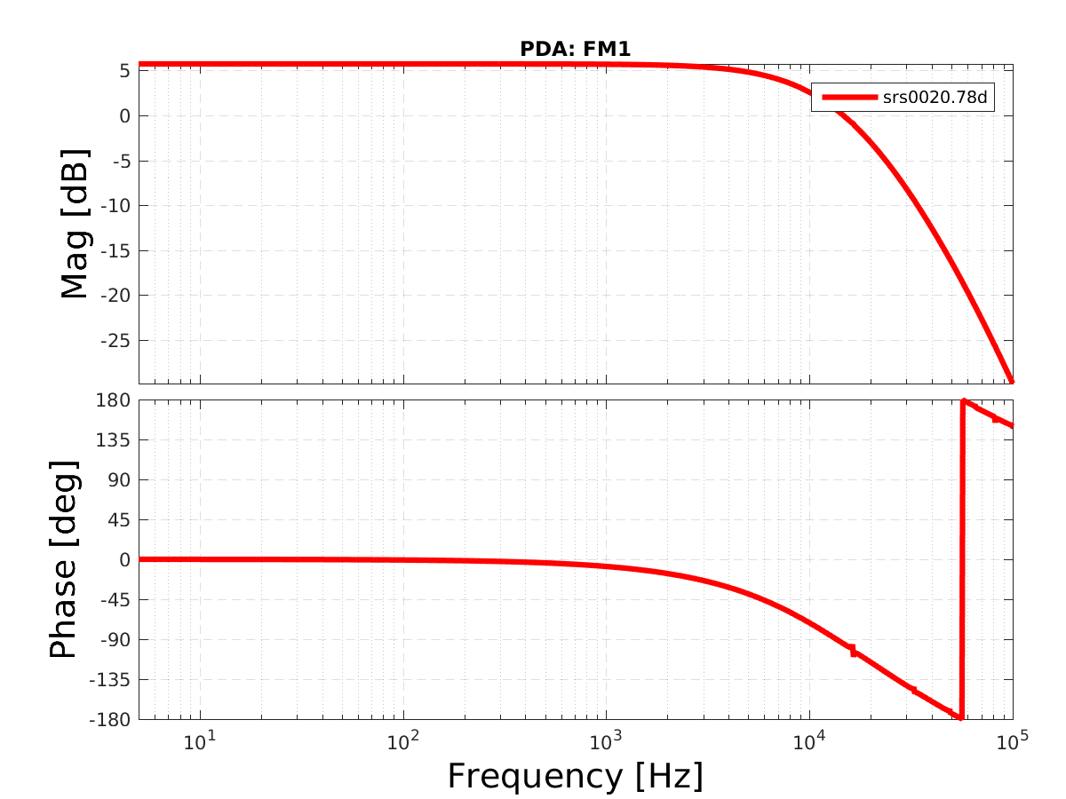
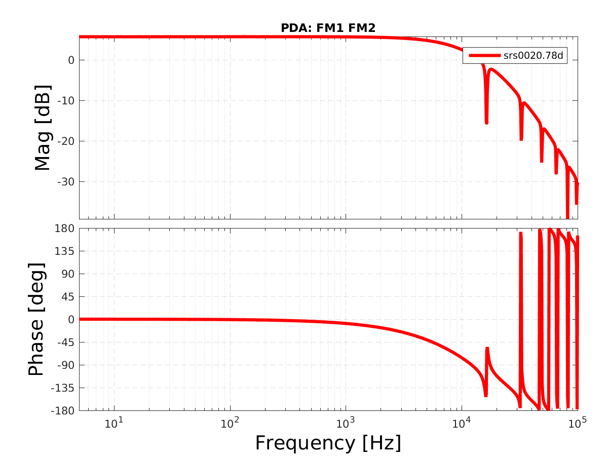
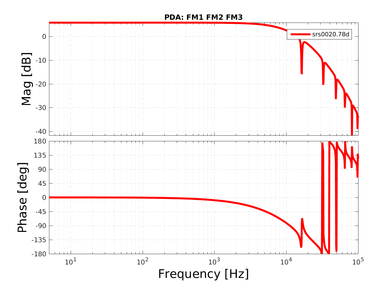
Attached are plots of

- Transfer function wit- over-without offset. The insanity is indeed gone.

- PDA: FM1, FM1FM2, FM1FM2FM3 - all normalized with their compensation filter.

- PDB: FM1, FM1FM2, FM1FM2FM3 - all normalized with their compensation filter.

In short: the current compensation is good at the 0.02dB level. One could still improve it...

The plotting MATLAB code is here: /ligo/home/controls/sballmer/20190304/DCPD

Images attached to this comment
jeffrey.kissel@LIGO.ORG - 10:43, Tuesday 05 March 2019 (47290)CAL, ISC
I've moved the contents of Stefan's results from his home directory on the local file system into the calibration SVN (though I've not yet modified his plotting script for the new directories and/or to spit out the right file names).

I used the follow commands to do so:
Data:
    cd /ligo/svncommon/CalSVN/aligocalibration/trunk/Common/Electronics/H1/Data/OMCWhiteningChassis/2019-03-04/
    cp /ligo/home/controls/sballmer/20190304/DCPD/SRS00* ./
    cp /ligo/home/controls/sballmer/20190304/DCPD/srs00* ./
    cp /ligo/home/controls/sballmer/20190304/DCPD/47254_20190303213* ./

Script:
    cd /ligo/svncommon/CalSVN/aligocalibration/trunk/Common/Electronics/H1/Scripts/
    cp /ligo/home/controls/sballmer/20190304/DCPD/plotData.m plot_omcdcpdwhiteningmods_20190304.m

Results:
    cd /ligo/svncommon/CalSVN/aligocalibration/trunk/Common/Electronics/H1/Results/OMCWhiteningChassis/
    cp /ligo/home/controls/sballmer/20190304/DCPD/PD*.png ./
    rename 's/PD/2019-03-04\_H1OMC\_WhiteningChassisTFs\_PD/' PD*.png

Thus the new script name to plot the data is:
    /ligo/svncommon/CalSVN/aligocalibration/trunk/Common/Electronics/H1/Scripts/plot_omcdcpdwhiteningmods_20190304.m

which should be modified to analyze the following data:
    /ligo/svncommon/CalSVN/aligocalibration/trunk/Common/Electronics/H1/Data/OMCWhiteningChassis/2019-03-04/
        SRS00*.78D
        srs00*.asc
using the notes in the file
    /ligo/svncommon/CalSVN/aligocalibration/trunk/Common/Electronics/H1/Data/OMCWhiteningChassis/2019-03-04/
        47254_20190303213544_DCPDWhiteningChanges.pdf

and to produce plots and results with similar file tags as
    /ligo/svncommon/CalSVN/aligocalibration/trunk/Common/Electronics/H1/Results/OMCWhiteningChassis/
        2019-03-04_H1OMC_WhiteningChassisTFs_PD*.png
(or the code should be re-written to use your favorite fitting code [maybe in python using IIRrational] and produce plots and results with similarly explicit file names with indications of the date, the interferometer, and WhiteningChassisTFs in the file name.)
ling.sun@LIGO.ORG - 14:16, Thursday 07 March 2019 (47358)

Lilli S.,

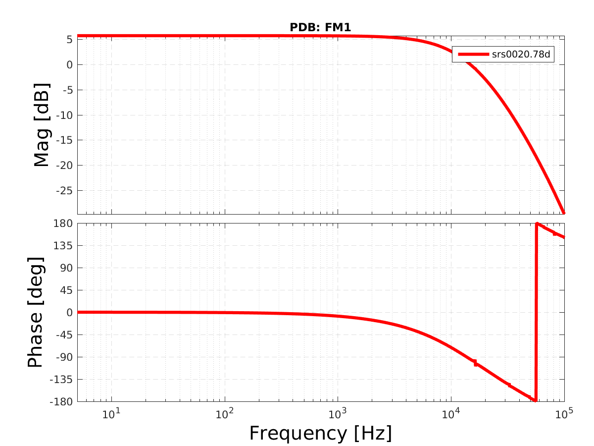
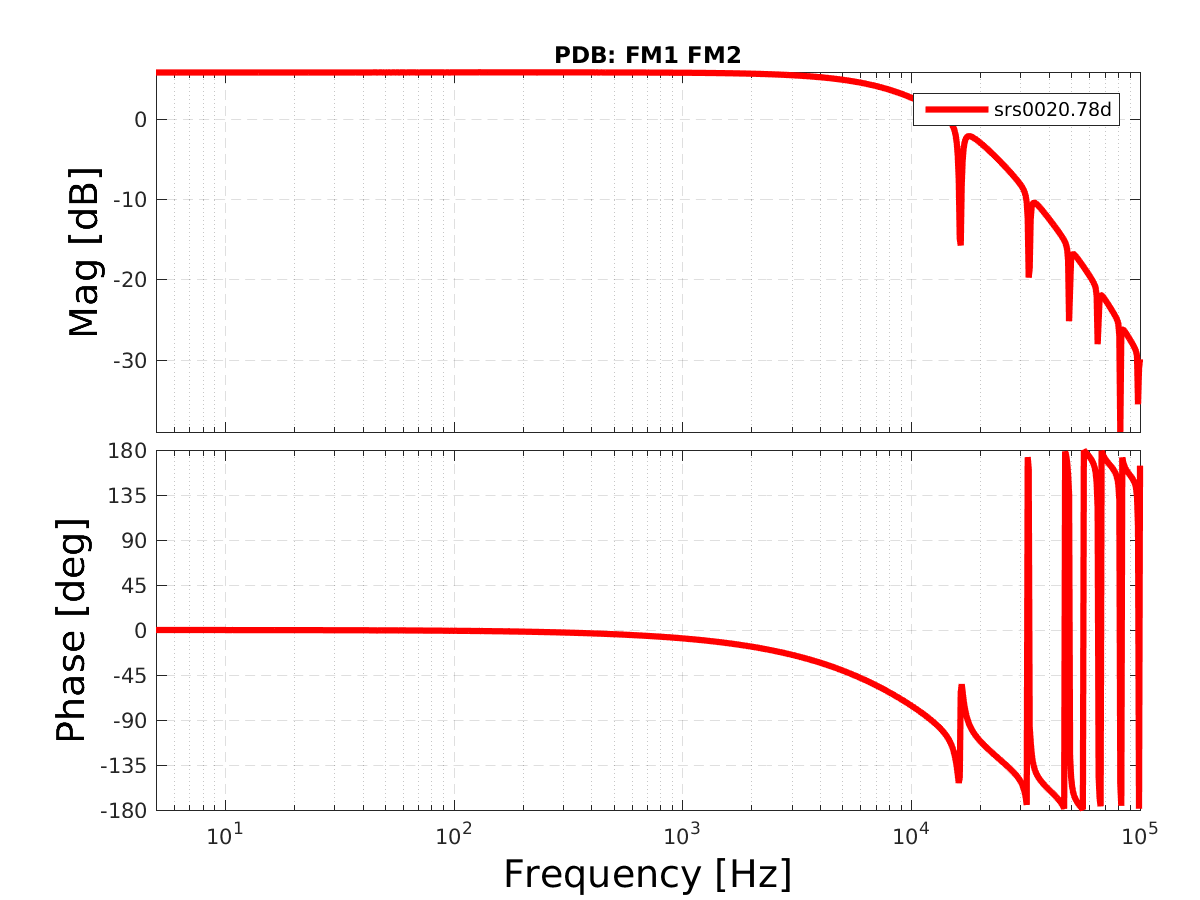
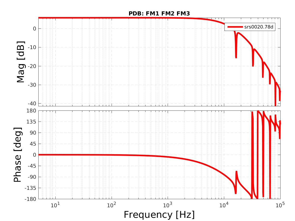
First, I have renamed the data files in dir /ligo/svncommon/CalSVN/aligocalibration/trunk/Common/Electronics/H1/Data/OMCWhiteningChassis/2019-03-04/, so that they match what is described in note /ligo/svncommon/CalSVN/aligocalibration/trunk/Common/Electronics/H1/Data/OMCWhiteningChassis/2019-03-04/47254_20190303213544_DCPDWhiteningChanges.pdf

The test box has been factored out. (Test box data: /ligo/svncommon/CalSVN/aligocalibration/trunk/Common/Electronics/H1/Data/CoilDriverTestBox/S1900070/)

The fitting script is /ligo/svncommon/CalSVN/aligocalibration/trunk/Common/Electronics/H1/Scripts/fit_OMCDCPDWhiteningChassis_20190304.py 

The results are in the table below. The fitting plots are in the attachments.

The low-freq poles/zeros roughly match Stefan's results. In O1 and O2 we used 1 stage of whitening (FM1), and the high freq poles were at [(14.34e3 + 14.60e3)/2, (18.68e3 + 18.57e3)/2, (98.94e3 + 100.45e3)/2] Hz. The new fitting for FM1 is consistent with O1 and O2.

Take PDA FM1FM2FM3 noDC as an example, manually build TF by removing the high-freq zeros, and plot the residual -> see diff.pdf 

By ignoring the high-freq zeros, there's little impact on magnitude, but there's phase difference at higher freq (~<1 deg below 5k Hz).

  PDA PDB Comments
FM1FM2FM3 (no DC) PDA, Filters: FM1FM2FM3noDC Results: z:p:k
[  3.90426349e+06   3.90426349e+06   4.99892253e+02   1.08290122e+00
   1.08040698e+00]
[  1.04233314e+01   3.26866242e+04   3.26866242e+04   1.13980014e+04
   4.97078295e+01   1.04233314e+01]
-8.68011786846
PDB, Filters: FM1FM2FM3noDC Results: z:p:k
[  4.64029327e+06   4.64029327e+06   5.00447159e+02   1.07523773e+00
   1.07282309e+00]
[  1.03389750e+01   3.28642175e+04   3.28642175e+04   1.15193027e+04
   1.03389750e+01   4.97939024e+01]
-6.26981682358

Low-freq zeros near 1Hz, 1Hz, 500Hz, and poles near 10Hz, 10Hz, 50Hz (as expected)

High-freq poles near 12K, 33K, 33K Hz.

FM1FM2FM3 (4.99V DC) PDA, Filters: FM1FM2FM3DC Results: z:p:k
[  4.83659991e+06   4.83659991e+06   4.99682906e+02   1.08106936e+00
   1.08299624e+00]
[  1.04231076e+01   3.28748478e+04   3.28748478e+04   1.13460627e+04
   1.04231076e+01   4.96890494e+01]
-5.6929144981
PDB, Filters: FM1FM2FM3DC Results: z:p:k
[  3.93271594e+06   3.93271594e+06   5.00449636e+02   1.07585358e+00
   1.07328174e+00]
[  4.98000266e+01   3.28631506e+04   3.28631506e+04   1.15205406e+04
   1.03375026e+01   1.03375026e+01]
-8.72188264417

Low-freq zeros near 1Hz, 1Hz, 500Hz, and poles near 10Hz, 10Hz, 50Hz (as expected)

High-freq poles near 12K, 33K, 33K Hz.

FM1FM2 (no DC)

PDA, Filters: FM1FM2 Results: z:p:k
[  3.88449944e+06   7.08310144e+05   4.99921161e+02   1.17529230e+00]
[  8.83316503e+04   2.04242818e+04   1.22505800e+04   4.96735061e+01
   1.04906496e+01]
-8.30876928807

PDB, Filters: FM1FM2 Results: z:p:k
[  2.11805525e+06   8.72055868e+05   5.00733633e+02   1.14755102e+00]
[  2.04506589e+04   1.24360067e+04   8.94998324e+04   4.97729997e+01
   1.02056871e+01]
-12.7328787001

Low-freq zeros near 1Hz, 500Hz, and poles near 10Hz, 50Hz (as expected)

High-freq poles near 12K, 20K, 89K Hz.

FM1 (no DC) PDA, Filters: FM1 Results: z:p:k
[  4.22938089e+06   4.22938089e+06   1.17507390e+00]
[  1.27384958e+04   1.93716076e+04   9.29113659e+04   1.04895576e+01]
13.3497796427
PDB, Filters: FM1 Results: z:p:k
[  4.84207436e+06   4.84207436e+06   1.14699930e+00]
[  1.29122349e+04   1.93696499e+04   9.46279852e+04   1.02067553e+01]
10.4974545401

Low-freq zeros near 1Hz and poles near 10Hz (as expected)

High-freq poles near 13K, 19K, 93K Hz.

noFM (no DC) PDA, Filters: noFM Results: z:p:k
[  1.26091781e+07   3.57048935e+07   2.05610666e-01]
[  1.28075383e+04   1.92624890e+04   1.84656469e+06   4.98134421e-02]
0.980629117874
PDB, Filters: noFM Results: z:p:k
[  2.82948542e+07   2.84161583e+07   2.05615042e-01]
[  1.29617754e+04   1.93273505e+04   2.08761329e+06   4.98133861e-02]
0.629314166113

High-freq poles near 13K, 19K Hz.

Unphysical low-freq zero near 0.2Hz and pole near 0.05Hz.


Non-image files attached to this comment
jeffrey.kissel@LIGO.ORG - 17:52, Thursday 07 March 2019 (47377)CAL
Concluding from the results of the fit above, I'll be updating the calibration model parameters to change from the previous measurement of the DCPD whitening chassis (before O2, when the nominal configuration was to only have the first stage of whitening -- "F1" or "FM1" -- on; see LHO aLOG 28087) from 
                          PDA            PDB              PDA          PDB             PDA            PDB
    uncompOMCpoles_whitening = [(14.34e3 + 14.60e3)/2, (18.68e3 + 18.57e3)/2, (98.94e3 + 100.45e3)/2];
to the new fitted measurement results, and choosing the new nominal configuration, with all three filters on (the 1st and 3rd stages, which are whitening and the 2nd stage which is a low pass, i.e. "FM1FM2FM3" or "3 filt"), and using the 5 V_DC offset fit results because it's more representative of the nominal running conditions of the chassis (with the poles rounded to the nearest Hz) 
                          PDA            PDB               PDA             PDB                 PDA             PDB
    uncompOMCpoles_whitening = [(11.346e3 + 11.521e3)/2, (32.875e3 + 32.863e3)/2, (32.875e3 + 32.863e3)/2];
ling.sun@LIGO.ORG - 14:26, Friday 08 March 2019 (47394)

Lilli S.,

The residual contribution plot is attached. This was generated using /ligo/svncommon/CalSVN/aligocalibration/trunk/Common/Electronics/H1/Scripts/fit_OMCDCPDWhiteningChassis_20190304-vsOriginal.py

(based on reference model modelparams_H1_20190118)

The results is averaged after using different poles/zeros in PDA and PDB, instead of using the same set of averaged poles/zeros in PDA and PDB.

Non-image files attached to this comment
rich.abbott@LIGO.ORG - 07:52, Monday 11 March 2019 (47418)ISC
Per Jeff's request that the original DCPD files be included, I am attaching the data extending down to 0.5Hz for the OMC DCPD Whitening chain as taken on the floor by signal injection into the front panel of the Split Whitening Chain via an SR785
Non-image files attached to this comment
ling.sun@LIGO.ORG - 10:23, Tuesday 12 March 2019 (47453)

Attached are two plots:

A) The comparison of TFs:

1. All low-freq z:p + high-freq p + out-of-band z from IIRrational fitting

2. Dead reckoned z:p = [500, 1, 1]:[50, 10, 10]

3. Low-freq z:p from Stefan's fitting in 47257

4. Low-freq z:p from Stefan's fitting in 47257 + high-freq p from IIRational

B) The comparison of contribution residuals, by using the latest H1 model 20190301

The scripts live in

/ligo/svncommon/CalSVN/aligocalibration/trunk/Common/Electronics/H1/Scripts/fit_OMCDCPDWhiteningChassis_20190304-compareTF.py

/ligo/svncommon/CalSVN/aligocalibration/trunk/Common/Electronics/H1/Scripts/fit_OMCDCPDWhiteningChassis_20190304-compareRes.py


Non-image files attached to this comment
Displaying reports 42621-42640 of 88668.Go to page Start 2128 2129 2130 2131 2132 2133 2134 2135 2136 End