Displaying reports 43261-43280 of 88648.Go to page Start 2160 2161 2162 2163 2164 2165 2166 2167 2168 End
Reports until 16:24, Monday 04 February 2019
H1 ISC
sheila.dwyer@LIGO.ORG - posted 16:24, Monday 04 February 2019 - last comment - 18:10, Monday 04 February 2019(46778)
glitches in ALS X arm, fiber bypass test

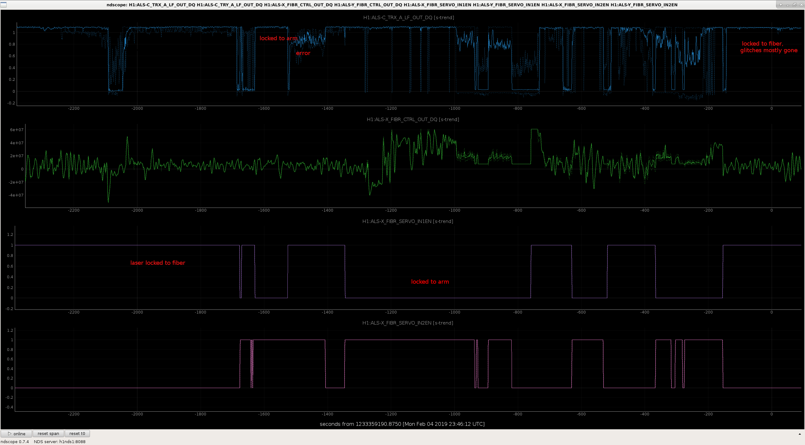
today it is snowing, and we have been having ALS glitches in the X arm for the last 45 minutes or so.  

We wrote a quick script to transition the green lock to the configuration where the fiber is bypassed, and switched back and forth a few times.  The attached text file can just be copied and pasted into a guardian shell, to either transition to the bypassed configuration or back to the normal configuration, you will also need to change the guardain request as the text file tells you to.  

In the attached screenshot you can see that when IN1EN is 1, we are locked with the laser to the PLL , and there is some fuzz on the X arm transmission which is a series of small fast glitches if the plot were more zoomed in.  When IN2EN is 1 we are locked directly to the arm, and in the first couple of examples this does seem to be quieter than with the laser locked to the fiber.  There was a time labeled error when we accidentally left both feedback paths on, we can ignore this. 

The arm comes unlocked fairly often when we are locked with the fiber bypassed.  Next time this happens and we have time to work on this we should go the end station and take some time to measure the transfer function of this lock to the arm. 
Images attached to this report
Non-image files attached to this report
Comments related to this report
sheila.dwyer@LIGO.ORG - 18:10, Monday 04 February 2019 (46779)

We have had other difficulties locking today, with the CARM offset reduction. 

Last sunday, after the computer crash we had moved the VCO compensation filter in the TR CARM loop which used to be engaged when we transitioned to TR_CARM to later in the locking sequence, and we never understood why that was necessary.  Today we moved it back to earlier in the sequence and that has improved the stability of the TR CARM loop.  We also have been sometimes manually deceasing the gain in this path a bit to give us more stability through the CARM offset reduction.  We tried to put this into the guardian once, but that didn't work so we have removed it again.
H1 General
yannick.lecoeuche@LIGO.ORG - posted 16:14, Monday 04 February 2019 (46777)
Shift Summary - Day

TITLE: 02/04 Day Shift: 16:00-00:00 UTC (08:00-16:00 PST), all times posted in UTC

STATE of H1: Commissioning

INCOMING OPERATOR: None

SHIFT SUMMARY:


14:40 (6:40) Chris traveling arms to assess tumbleweed buildup

16:00 (8:00) Start of shift

17:45 (9:45) Hugh to EX -- look at anemometer

17:46 (9:46) Terry to Optics Lab

17:55 (9:55) Marc, Fil to Vault -- PEM system calibration

18:04 (10:04) Terry back from Optics Lab

18:12 (10:12) Kyle to MY -- wiring on prototype vacuum equipment

18:18 (10:18) Hugh back from EX

18:34 (10:34) Patrick to MSR

19:07 (11:07) CALEX, CALEY restart

19:13 (11:13) Vanessa to EX, EY, MY

19:43 (11:43) Kyle back from MY

20:00 (12:00) Marc, Fil back from Vault

22:00 (14:00) Nutsinee to LVEA

23:19 (15:19) Nutsinee out of LVEA

00:00 (16:00) End of shift

H1 ISC
daniel.sigg@LIGO.ORG - posted 15:54, Monday 04 February 2019 - last comment - 13:26, Tuesday 05 February 2019(46775)
OMC model changes

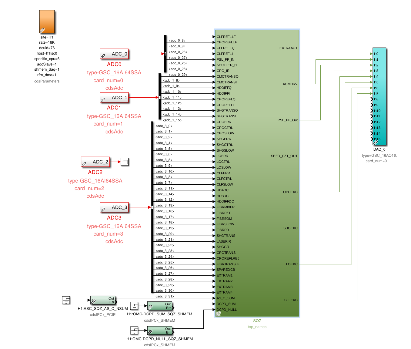
In preparation for adding the second HV driver to the OMC PZT driver chassis, the OMC model was updated.

  1. Remove all references to the old software trigger infrastructure.
  2. Add a new filter module PZT3 to apply the bias.
  3. Use the previous "fast shutter trigger" channel as the new output (chn 3 on the DB9 DAC channel).
  4. Added new readback channels for DC & AC. These are chns 3 & 4 on the DB9 cable coming from the DC PD interface chassis.
Comments related to this report
daniel.sigg@LIGO.ORG - 13:26, Tuesday 05 February 2019 (46792)

Model has been restarted with new channels.

H1 CDS (DAQ)
david.barker@LIGO.ORG - posted 15:45, Monday 04 February 2019 (46774)
Monday morning restarts.

Jamie, Jeff K, Jonathan, Nutsinee, Dave:

To get a jump on some restarts while we had high winds, the following were restarted Monday morning:

h1calcs, h1calex and h1caley models were restarted.

h1odcmaster was removed from the DAQ (the master file).

The requested DAQ channels were added to the DAQ-GDS broadcaster.

DAQ was restarted. Several problems were found:

We removed SQZ_PLL from the GRD INI file, and I removed the duplicated GDS channels.

DAQ was restarted a second time. Unfortunately H1EDCU_GRD.ini had been created with the new guardian version, which put in additional status channels which won't exists on the running system until tomorrow's upgrade. We will run with a red EDCU until that time. I also found an ODCMASTER entry in H1EDCU_DAQ.ini which I had missed, this will also go in tomorrow.

h1odcmaster was removed in the rtsystab file, the model was stopped on h1oaf0.

I removed h1odcmaster from the following MEDM Overview screens: CDS, IPC, DAQ.

DAQ Data Concentrator log level. Jonathan changed the log level on h1dc0 from 2 to 5.

(*) note to self, my script which checks for duplicate channels in the DAQ needs to also check the Broadcaster file

H1 TCS
thomas.shaffer@LIGO.ORG - posted 15:34, Monday 04 February 2019 (46771)
TCS Weekly Chiller Check

FAMIS11477

No water was added to either chiller, both chillers were at the same level as last week's check. (yay!).

H1 CDS
jonathan.hanks@LIGO.ORG - posted 13:43, Monday 04 February 2019 - last comment - 15:26, Monday 04 February 2019(46767)
cdsfs0 rebooted, unexpectedly.
The main file server rebooted around 13:03 localtime.  At this time we do not know why.  We had to manually mount the zfs filesystems and export the network shares to make /ligo (home directories, some applications) available to the workstations.
Comments related to this report
david.barker@LIGO.ORG - 15:26, Monday 04 February 2019 (46770)

on h0epics, I started the following EPICS IOCs: dewpoint_sensor, dust[lvea, lab, ex, ey, dr], weather[ex, ey, mx, my]

H1 PSL (PSL)
yannick.lecoeuche@LIGO.ORG - posted 12:46, Monday 04 February 2019 (46764)
PSL Status Report-Weekly


Laser Status:
Front End Power is 32.21W (should be around 30 W)
70W Output Power is 71.24W
Front End Watch is GREEN
70W Watch is GREEN

PMC:
It has been locked 12 days, 22 hr 11 minutes (should be days/weeks)
Reflected power = 10.7Watts
Transmitted power = 54.57Watts
PowerSum = 65.27Watts.

FSS:
It has been locked for 0 days 0 hr and 10 min (should be days/weeks)
TPD[V] = 2.761V (min 0.9V)

ISS:
The diffracted power is around 2.1%
Last saturation event was 0 days 0 hours and 11 minutes ago (should be days/weeks)


Possible Issues:


H1 AOS (AOS, SUS)
yannick.lecoeuche@LIGO.ORG - posted 12:35, Monday 04 February 2019 (46761)
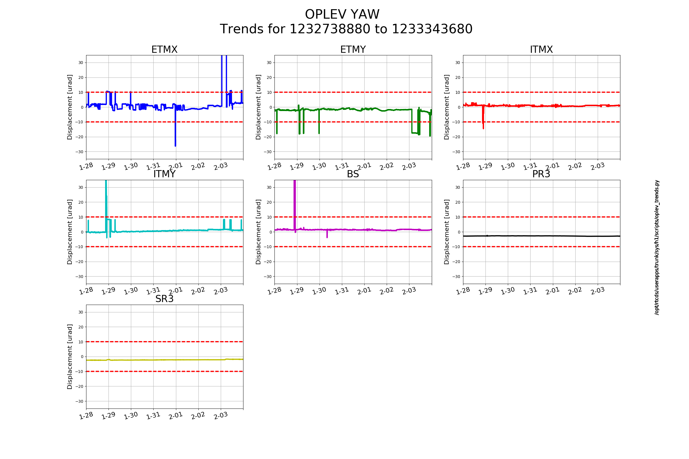
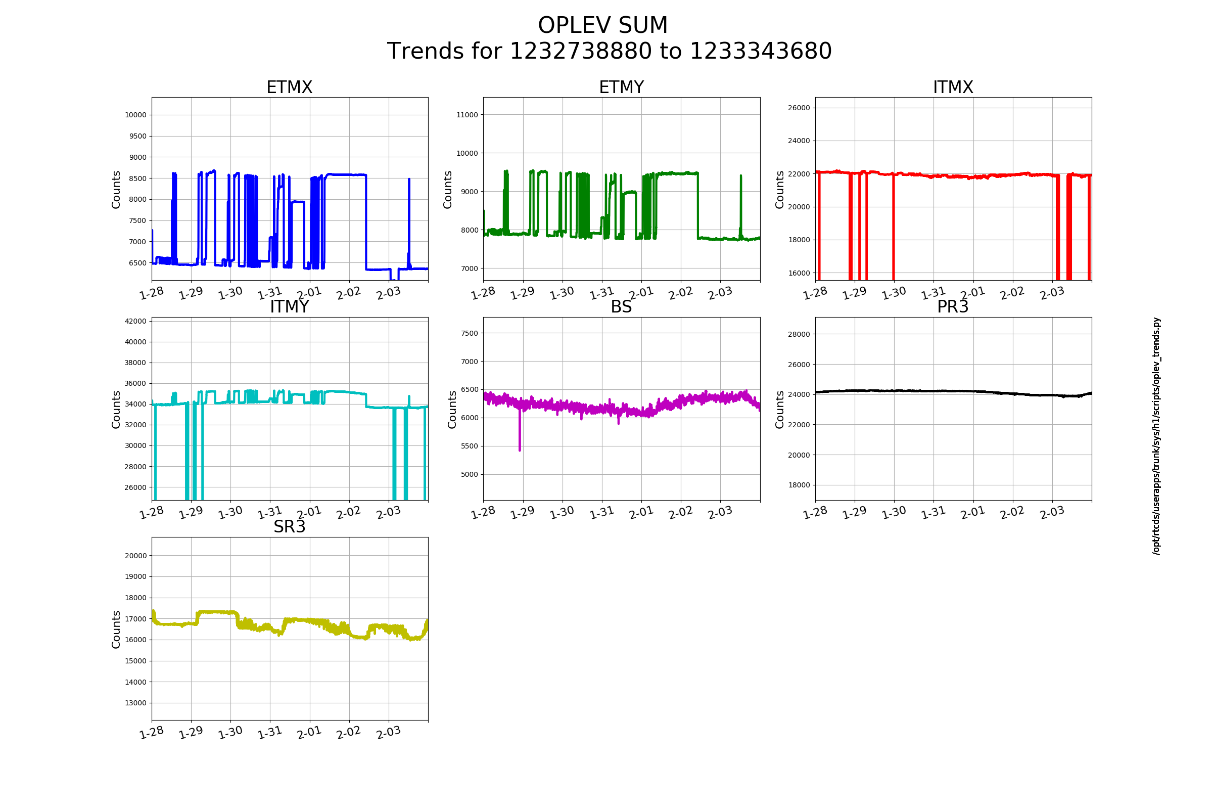
Optical Lever 7 Day Trends

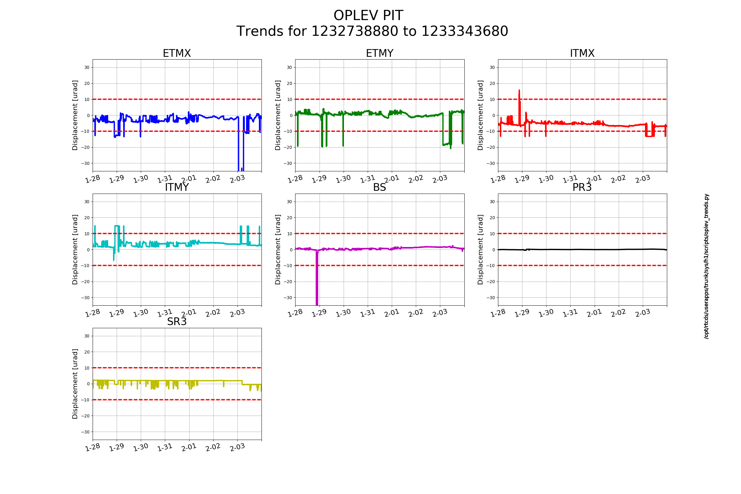
Oplevs appear to be fairly well centered

Images attached to this report
H1 AOS
jeffrey.kissel@LIGO.ORG - posted 11:23, Monday 04 February 2019 - last comment - 13:59, Monday 04 February 2019(46758)
h1calcs, h1calex, h1caley model changes installed TODAY (ahead of Tuesday Maintenance, due to weather and low IFO impact)
D. Barker, J. Kissel, J. Rollins
WP 8070
WP 8077

We've compiled, installed, and restarted the following changes to CAL models:
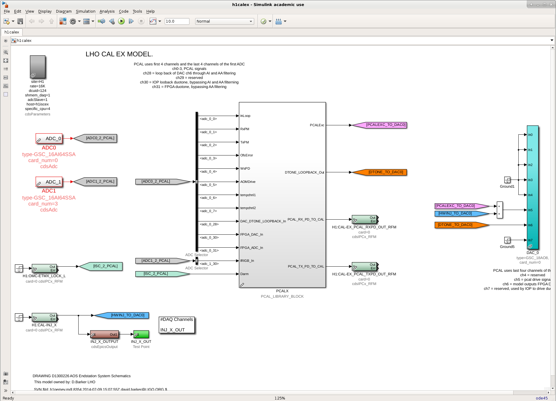
h1calex
(1) Removed the last of the old hardware injection infrastructure (top-level model change WP 8077).
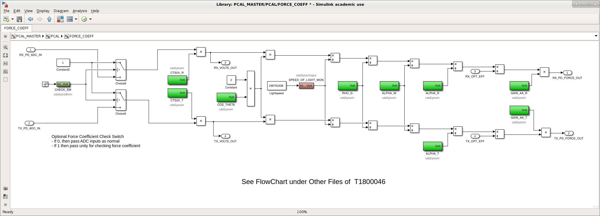
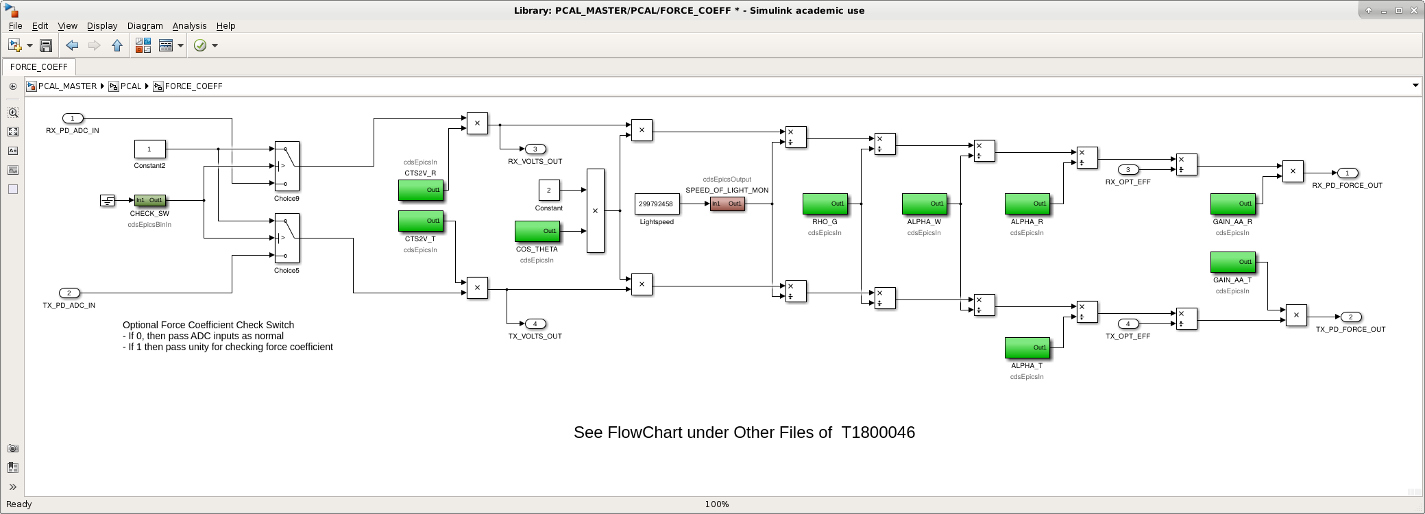
(2) Added switch for FORCE COEFF calculation check (by changing PCAL_MASTER)

h1caley
(2) Added switch for FORCE COEFF calculation check (by changing PCAL_MASTER)

h1calcs
(3) Installed whitening (high pass) filters to change dynamic range of the signals going in to the CFTD actuator path (just updated the CAL_CS_MASTER library part; see details in LLO:42961)
(4) Added additional EPICS records to calculate the time dependence of the sensing function's optical spring parameters from the ~15-20 Hz PCAL line (instead of needing the additional ~8Hz line).

As an additional step to item (4), we added the following 
    H1:CAL-CS_TDEP_PCAL_LINE1_REF_A_PUM_IMAG
    H1:CAL-CS_TDEP_PCAL_LINE1_REF_A_PUM_REAL
    H1:CAL-CS_TDEP_PCAL_LINE1_REF_A_TST_IMAG
    H1:CAL-CS_TDEP_PCAL_LINE1_REF_A_TST_REAL
    H1:CAL-CS_TDEP_PCAL_LINE1_REF_A_UIM_IMAG
    H1:CAL-CS_TDEP_PCAL_LINE1_REF_A_UIM_REAL
    H1:CAL-CS_TDEP_PCAL_LINE1_REF_C_NOCAVPOLE_IMAG
    H1:CAL-CS_TDEP_PCAL_LINE1_REF_C_NOCAVPOLE_REAL
    H1:CAL-CS_TDEP_PCAL_LINE1_REF_D_IMAG
    H1:CAL-CS_TDEP_PCAL_LINE1_REF_D_REAL
to the GDS broadcaster.

One more change that we'll install tomorrow in support of (1)
h1iscex
(5) We removed the ODC block and all IPC senders and receivers in support of item (1) from h1pcalex.

For item (1), I changed and committed:
/opt/rtcds/userapps/release/cal/h1/models/
    h1calex.mdl
    h1caley.mdl

For item (2) I changed and committed:
/opt/rtcds/userapps/release/cal/common/models/
    PCAL_MASTER.mdl

For items (3) and (4), I changed and committed:
/opt/rtcds/userapps/release/cal/common/models/
    CAL_CS_MASTER.mdl

For item (5), I changed and committed:
/opt/rtcds/userapps/release/isc/h1/models/
    h1iscex.mdl

Images attached to this report
Comments related to this report
jeffrey.kissel@LIGO.ORG - 12:45, Monday 04 February 2019 (46763)
J. Kissel

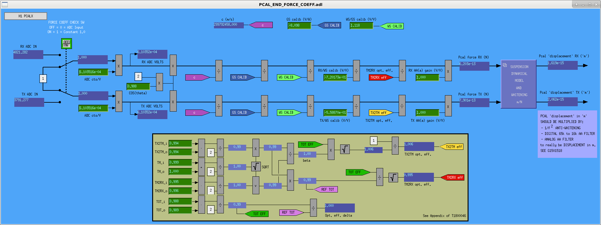
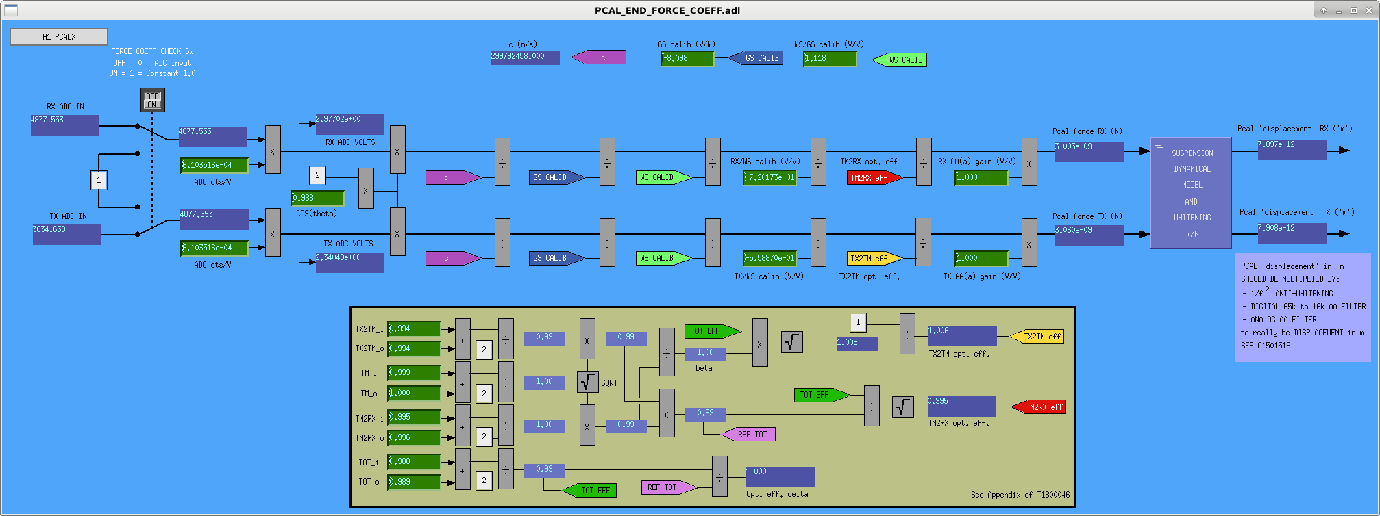
I've changed common PCAL MEDM screen to support the new FORCE_COEFF_CHECK_SW. Attached shows switch functionality ON vs OFF.

Changes committed to 
/opt/rtcds/userapps/release/cal/common/medm/
    PCAL_END_FORCE_COEFF.adl
Images attached to this comment
jeffrey.kissel@LIGO.ORG - 13:59, Monday 04 February 2019 (46768)
J. Kissel

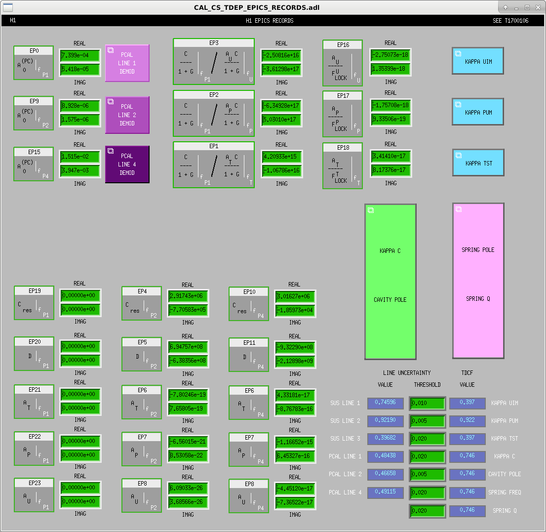
Modified MEDM screen for EPICs records addition of PCAL_LINE1 channels described above (EP19-23).

Changes committed to 
/opt/rtcds/userapps/release/cal/common/medm/
    CAL_CS_TDEP_EPICS_RECORDS.adl

Screenshot attached.
Images attached to this comment
H1 TCS (AWC, TCS)
daniel.vander-hyde@LIGO.ORG - posted 20:41, Sunday 03 February 2019 - last comment - 14:40, Monday 04 February 2019(46755)
SRM heater alignment attempt #2 (Yaw still clipping)

Satoshi, Danny 

     Continuing from our last attempt (alog 46692) we sought to finish this up by increasing our range in yaw without clipping on the SRM AR baffle but this still proved to be difficult. We first tried walking the beam using both upper and lower periscope mirrors and then resorted to shifting the table. After trying various configurations we decided to think about it more carefully before attempting again on Tuesday.   

Comments related to this report
aidan.brooks@LIGO.ORG - 12:19, Monday 04 February 2019 (46760)

Would it be possible to add more detail to this? What is the metric you're using to determine the alignment?

daniel.vander-hyde@LIGO.ORG - 14:40, Monday 04 February 2019 (46766)AWC, TCS

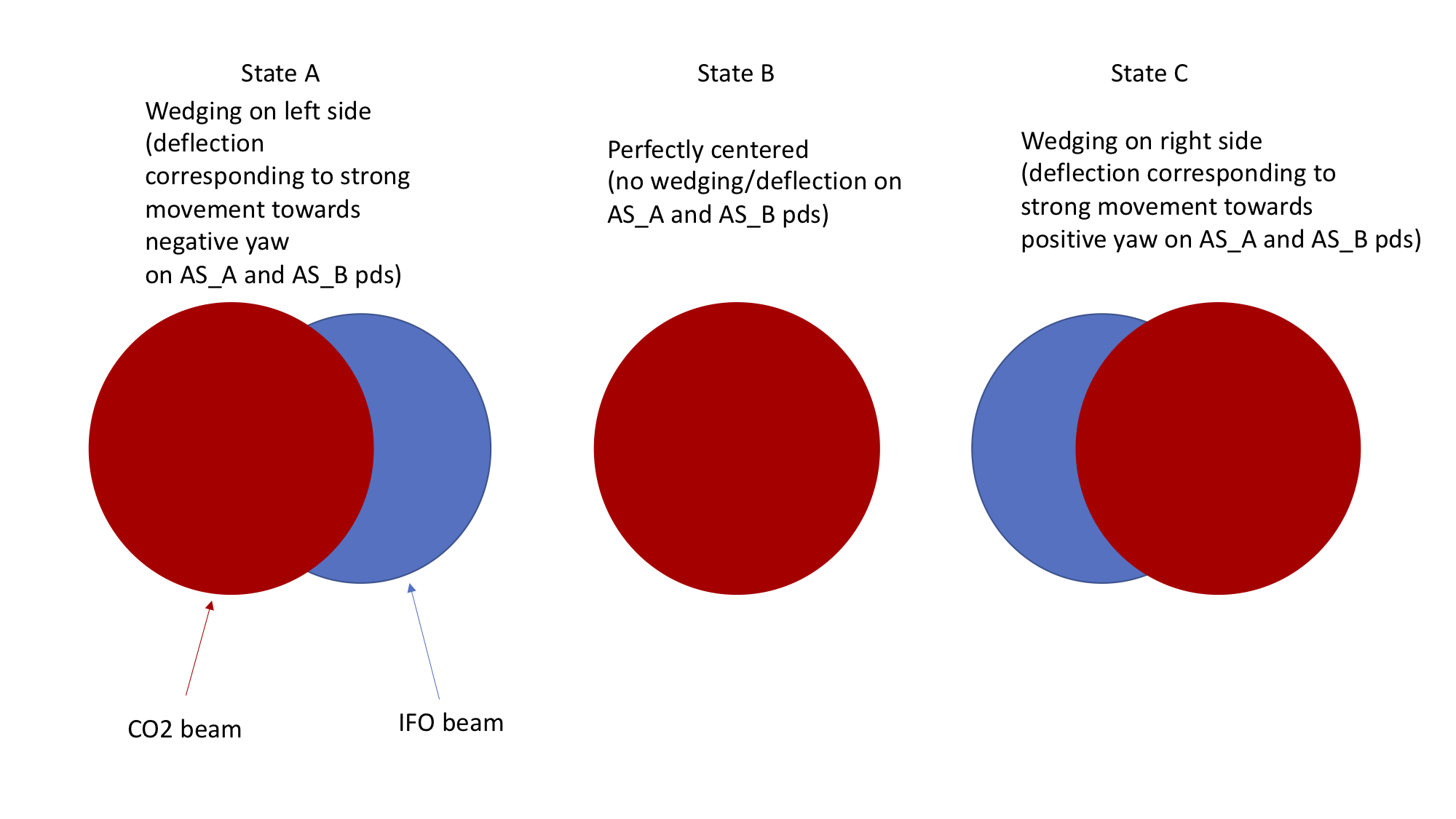
The metric we are using is the amount of deflection we see on the AS_A and AS_B photodiodes (with the IFO in single bounce)

We are currently using the following method to align: 

  • Make sure you are not clipping on the mirror apertures or baffles using the red alignment laser and can see the transmission of the red laser onto the SRM-HR baffle through the viewport adjacent to the Zn-Se viewport. 
  • When scanning the back of the SRM with the CO2 you expect the CO2 to create a wedge as you get close enough to the ifo beam which corresponds to a strong deflection on the aforementioned PDs
  • If given enough range, you should be able to pass the CO2 over the ifo beam which would correlate to the behavior shown in the figure attached (I use yaw as the example). 
  • Fine tune alignment to achieve State B. 

Results:

  • We have used this method to achieve good centering in pitch. 
  • In yaw, we see the behavior in State A (in the figure) but we start clipping on the SRM-AR baffle before we can start to see State B and State C. 


Images attached to this comment
H1 CAL (CAL, ISC, SUS)
jeffrey.kissel@LIGO.ORG - posted 18:14, Sunday 03 February 2019 - last comment - 10:26, Wednesday 13 February 2019(46754)
H1 SUS ETMX Driver Electronics Measurements Complete
R. Abbott, J. Kissel

Rich and I measured detailed transfer functions of SUS ETMX's driver electronics today. More details to come, but we were at EX measuring from about 11a to 6p with things disconnected, the SUS ETMX guardian in SAFE, and the SEI chamber guardian in DAMPED. All driver electronics (and associated cabling) suspensions, platforms, and guardians have been restored to nominal functionality.

The raw data can be found here:
/ligo/svncommon/CalSVN/aligocalibration/trunk/Common/Electronics/H1/Data/SUSElectronics/ETMX/
    UIM/2019-02-03/
    PUM/2019-02-03/
    TST/2019-02-03/

The file names are only labeled by date, so the key to translate the filenames into useful quadrant / coil and switch state information is found in the measurement notes in each directory,
/ligo/svncommon/CalSVN/aligocalibration/trunk/Common/Electronics/H1/Data/SUSElectronics/ETMX/
    UIM/2019-02-03/2019-02-03_UIMdriver_measurementnotes.txt
    PUM/2019-02-03/2019-02-03_PUMdriver_measurementnotes.txt
    TST/2019-02-03/2019-02-03_ESDLVDriver_measurementnotes.txt
Comments related to this report
jeffrey.kissel@LIGO.ORG - 10:26, Wednesday 13 February 2019 (46927)
Here's the analog electronics measurement setups for this data.

This time (unlike the 2016 attempt; see the last page of LHO:24725), we tried to cut corners by only driving the coil drivers with single-ended input directly from the SR785 -- so we can avoid having to characterize the details of the differential driver box that has been used previously. This failed, causing (what we believe to be saturations) of the coil driver electronics and wonky unphysical transfer functions. This is especially evident with the PUM driver's switchable "acquire" circuits engaged, and in the UIM driver after the second and third low-pass filters are in engaged. Finally, comparing against measurements taken with the coil driver monitor circuits (LHO:46854) it's dreadfully obvious.

More investigation is required as to what's going on, but sadly those investigations take time that we don't have.
I'm proceeding with attempting to fit a combination of the un-spoiled SR785 data and the less-complete-and-more-complicated monitor circuit data taken with DTT (again, LHO:46854).

The ESD driver measurements (at least) appear to be good enough to move forward, as indicated by the table of results above.
Non-image files attached to this comment
evan.goetz@LIGO.ORG - 16:02, Monday 04 February 2019 (46773)
Using the data from Jeff and Rich's measurements, I have fitted the ESD driver electronics. However, I ran into problems when trying to fit the PUM and UIM measurements. The raw output of the transfer function measurements looks unfamiliar to previous measurements and has puzzled Jeff and Rich when I showed it to them.

1) Summary plots from ESD driver measurements and fits
2) Puzzling PUM driver measurements
3) Puzzling UIM driver measurements

Scripts for analysis of the data is located at:
$CALSVN/trunk/Common/Electronics/H1/Scripts/model_ETMX_*_20190203.m
and plots are found at:
$CALSVN/trunk/Common/Electronics/H1/Results/SUSElectronics/ETMX/[UIM,PUM,TST]/2019-02-03/

The fit results for the ETMX ESD driver electronics is given below.
Quadrant                   Low pass [z;p] (Hz)                             Summing node [z;p] (Hz)
-----------------------------------------------------------------------------------------------------------------------
UL        [13.871+/-0.721, 15.668+/-0.748; 2.186, 2.186]       [129.736e3+/-2.818e3; 3.213e3+/-15.78, 31.549e3+/-381.9]
LL        [13.666+/-0.817, 15.570+/-0.850; 2.163, 2.163]       [90.736e3+/-694; 3.177e3+/-7.088, 26.699e3+/-145.6]
UR        [14.9049, 14.9054; 2.2222, 2.2223]                   [93.521e3+/-729; 3.279e3+/-7.534, 26.617e3+/-146.2]
LR        [13.335+/-0.486, 15.861+/-0.513; 2.157, 2.157]       [131.520e3+/-2.867; 3.238e3+/-15.9, 31.618e3+/-380.8]

Note above that the UR quadrant fit looked odd when looking purely at magnitude residuals. We saw that there was about a 1% offset in the band of primary interest (1 Hz - 1 kHz) above ~30 Hz which we attribute to the fact that LISO is attempting to minimize the fit error on both magnitude and phase simultaneously. When fitting purely on magnitude, the discrepancy is greatly reduced, at the cost of a slightly larger wiggle on the phase error (still less than a degree).

These have not yet been installed into the SUS output filter banks, but should be done so at the next opportunity.

We will ruminate on the PUM and UIM measurements and attempt to repeat these, again, at the next opportunity.
Non-image files attached to this comment
H1 SQZ (SQZ)
nutsinee.kijbunchoo@LIGO.ORG - posted 17:01, Thursday 31 January 2019 - last comment - 16:12, Monday 04 February 2019(46730)
SQZ Pump power intensity servo is working (again)

Daniel, Nutsinee

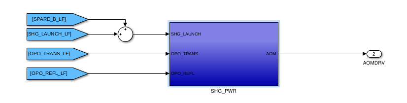
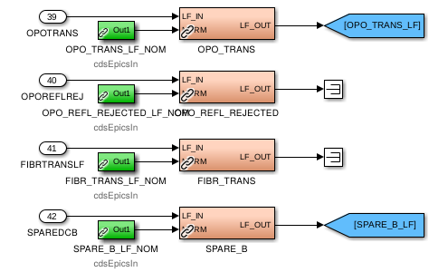
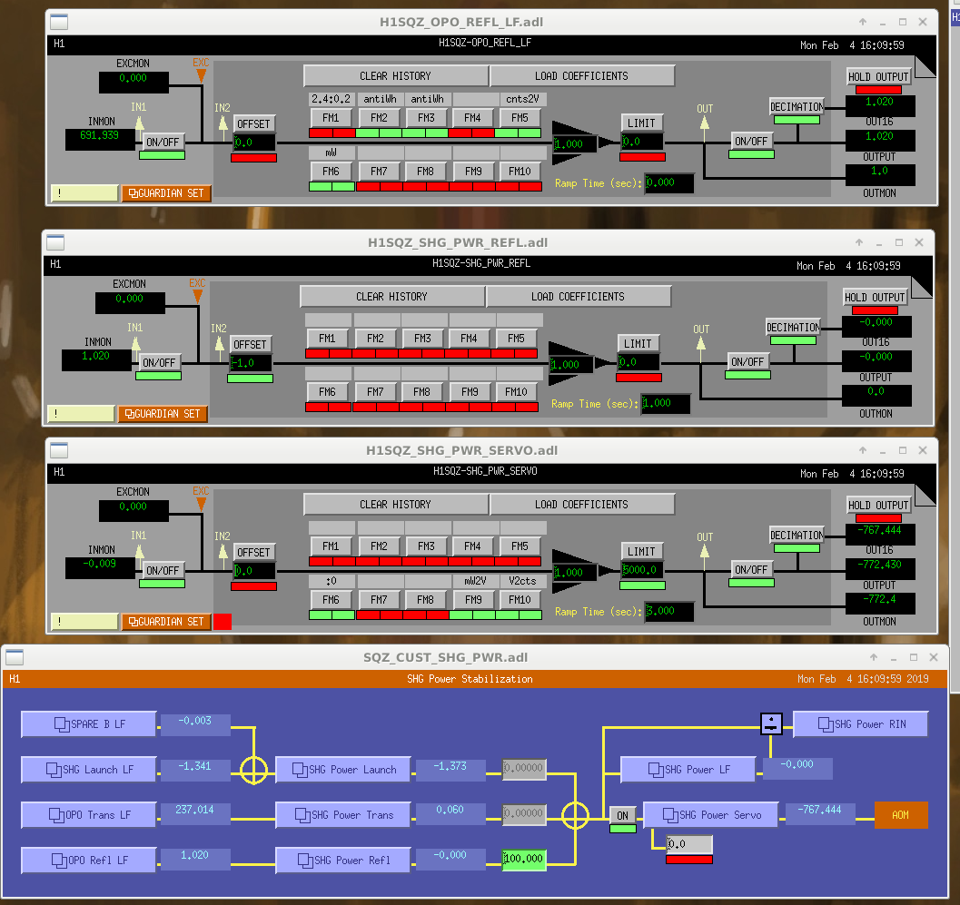
We had been using OPO common mode board for the intensity servo until we swapped the scheme (now the OPO CM board is actually used to lock the OPO). The servo is now all digital with a UGF of 200Hz. H1:SQZ-OPO_TRANS_LF_NOM has to be set to 1. The output (2nd from the left of SQZ rack U16) goes through a 450 Ohms resister and to the IFR that drives the AOM.

Images attached to this report
Comments related to this report
nutsinee.kijbunchoo@LIGO.ORG - 16:12, Monday 04 February 2019 (46776)

We found a filter that wasn't supposed to be on (an anti-whitening for a build-in whitening filter inside a PD, which OPO refl doesn't have). Fixed the mW2V gain (now 40) and the UGF of the intensity loop is now 100Hz. It no longer glitch when we turn the loop on. We also found that the whitening filter was turned off, which worked for the analog setup we used to have.

Images attached to this comment
H1 General (ISC, SUS)
stuart.aston@LIGO.ORG - posted 13:51, Thursday 31 January 2019 - last comment - 12:39, Monday 04 February 2019(46711)
QUAD suspension 3.3 Hz ring-up investigations
[Jeff K, Stuart A]

IIET: #11730

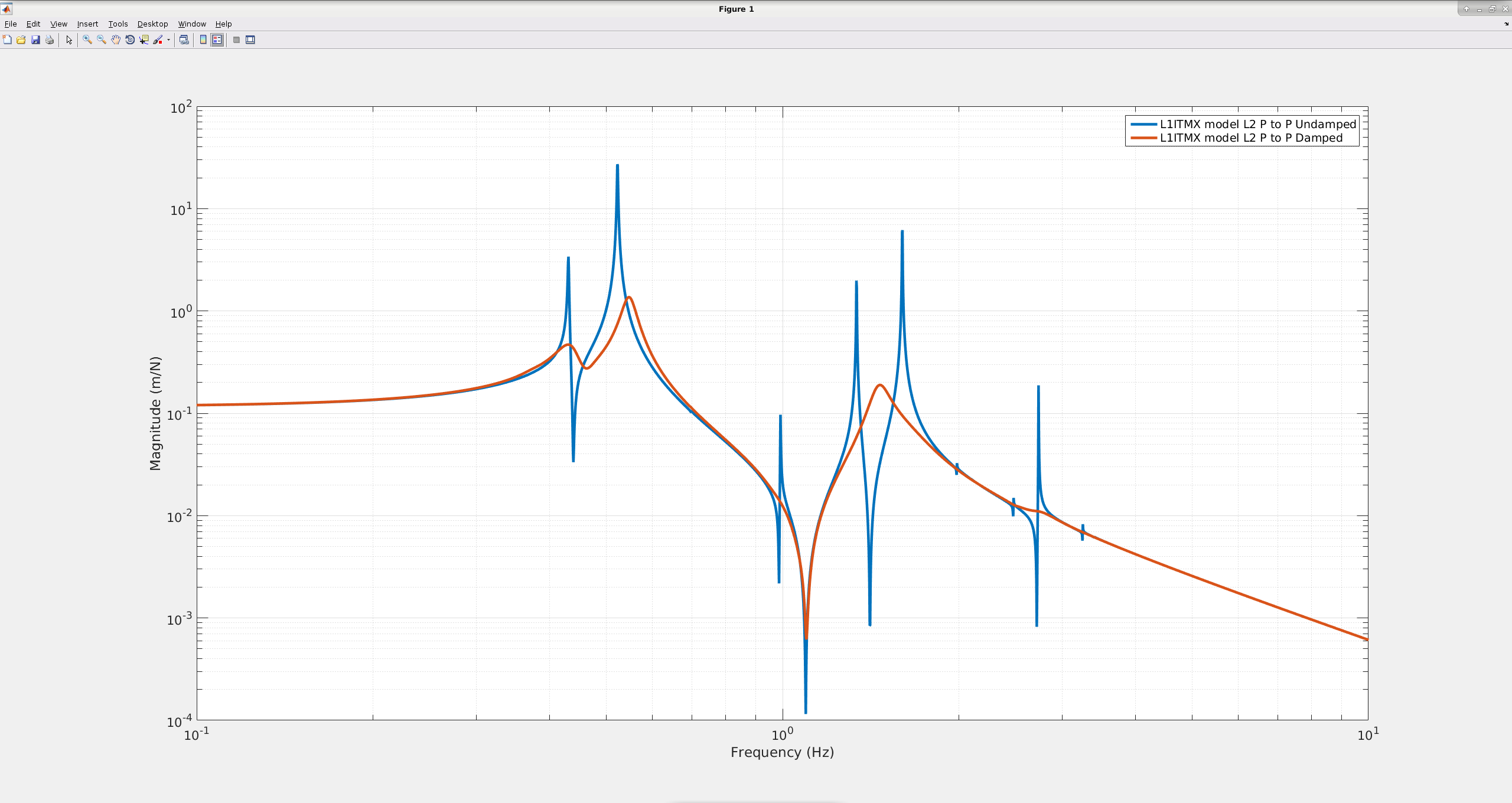
ITM QUAD suspensions at LLO have exhibited sharp ring-ups at 3.3 Hz from ASC pitch drive resulting in IFO lock-losses (see for example LLO aLOG entries: 40926, 40953, 40972 and 41501), as a work-around LLO currently employs a "TWO_LEGGED_HARDASC" scheme reducing ASC HARD drive from 4 QUADs to 2 QUADs i.e. just feeding back to the ETMs (see LLO aLOG entry 41502). The 3.3 Hz feature corresponds to the QUAD R3 Mode, which when looking at QUAD L2 P to P Damped TFs (see allquads_2019-01-30_AllSUSQUAD_Phase3b_L2_Damped_ALL_TFs.pdf below) which we have confirmed is also prominent in LHO QUAD suspensions too. However, at present, the 3.3 Hz R3 modes are not being rung-up at LHO.

Given there has been no change since O2 in the LLO QUAD local damping scheme, which demonstrates equally ineffective damping of the 3.3 Hz R3 mode as the LHO QUAD local damping scheme, thus, we believe there has been a change in the global control at LLO. This was not an issue at LLO during O2, so we suspect that changes in the ASC loops to handle higher IFO power have exacerbated the 3.3 Hz ring-up problem.

We found that the 3.3 Hz R3 mode is not well modeled in the QUAD dynamical model (see L1ITMX_Model_L2_PtoP below) which also suggests that the R3 mode should be completely damped n.b. we imported L1 ITMX live damping filters.

Therefore, we are now attempting to adjust QUAD dynamical model parameters to better fit the measured QUAD TF data. Failing this approach, we may seek to resurrect the QUAD model fitting code T1100163.
Images attached to this report
Non-image files attached to this report
Comments related to this report
stuart.aston@LIGO.ORG - 12:39, Monday 04 February 2019 (46762)SUS
Noting R3 mode frequencies for each QUAD measured from the TFs (n.b. most recent L1 TF data is taken in 2018 and most recent H1 data was from taken in 2014):

L1 ITMX = 3.32 Hz
L1 ITMY = 3.32 Hz
L1 ETMX = 3.188 Hz
L1 ETMY = 3.195 Hz

H1 ITMX = 3.32 Hz
H1 ITMY = 3.31 Hz
H1 ETMX = 3.01 Hz
H1 ETMY =  No TF Data
H1 AOS (ISC)
craig.cahillane@LIGO.ORG - posted 17:42, Tuesday 29 January 2019 - last comment - 20:49, Monday 04 February 2019(46683)
What is the arm power 2
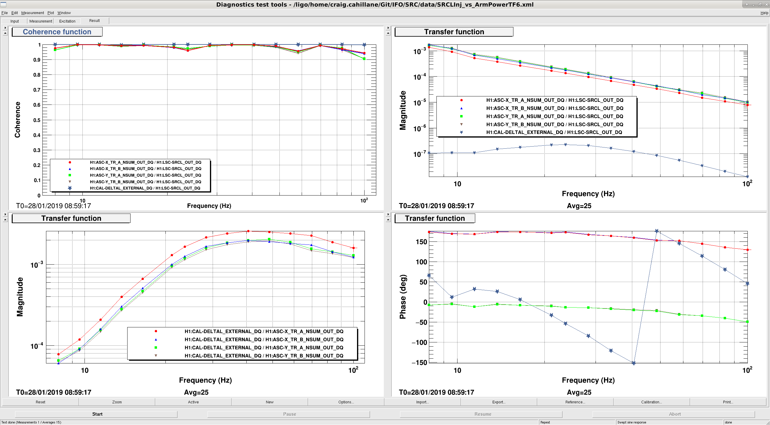
On January 8th I tried to measure the average arm power by dithering SRCL.  Last night I did it again, this time with better TFs taken simultaneously.

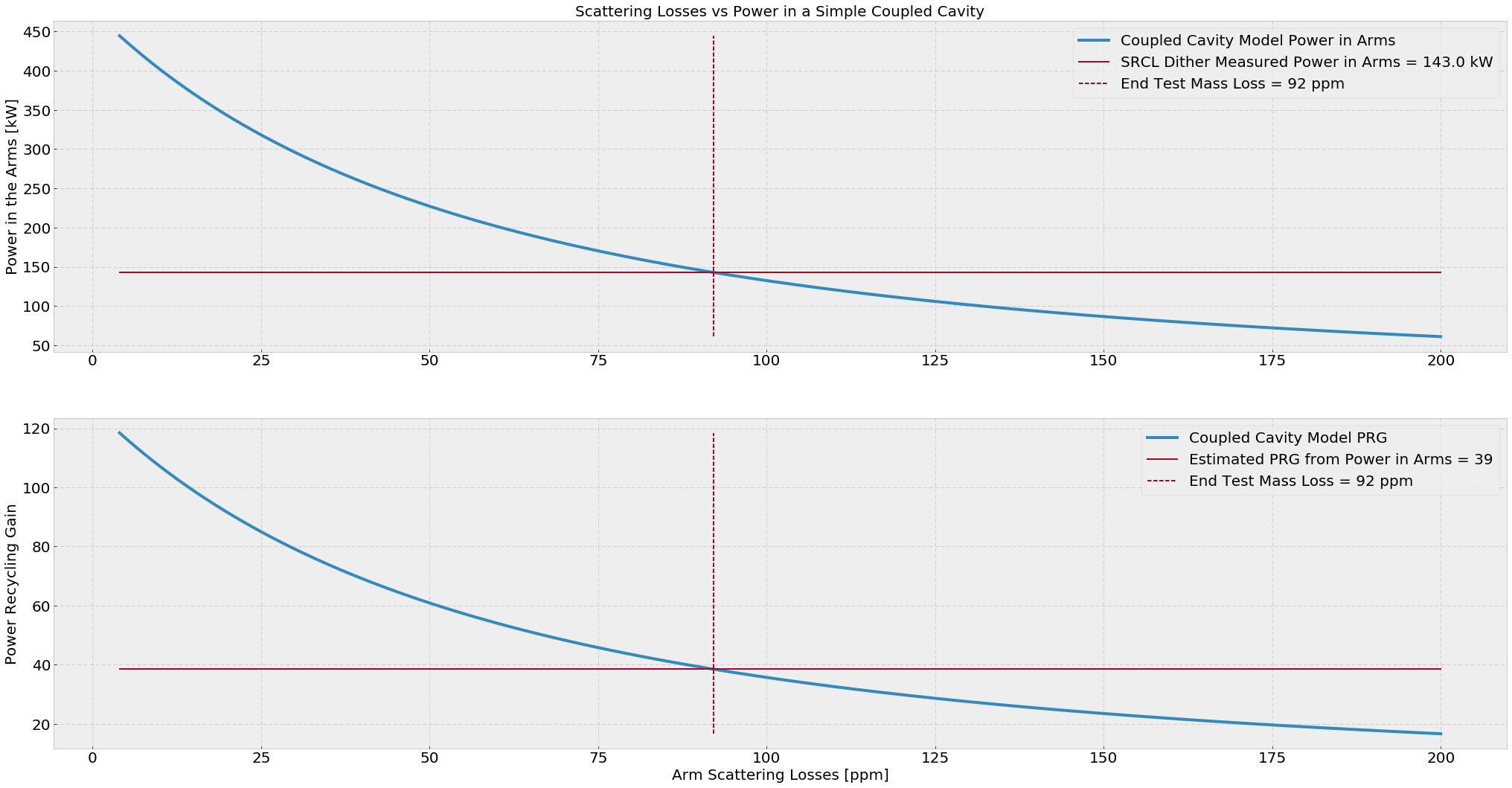
Average Arm Power = 143.0 +- 5.8 kW

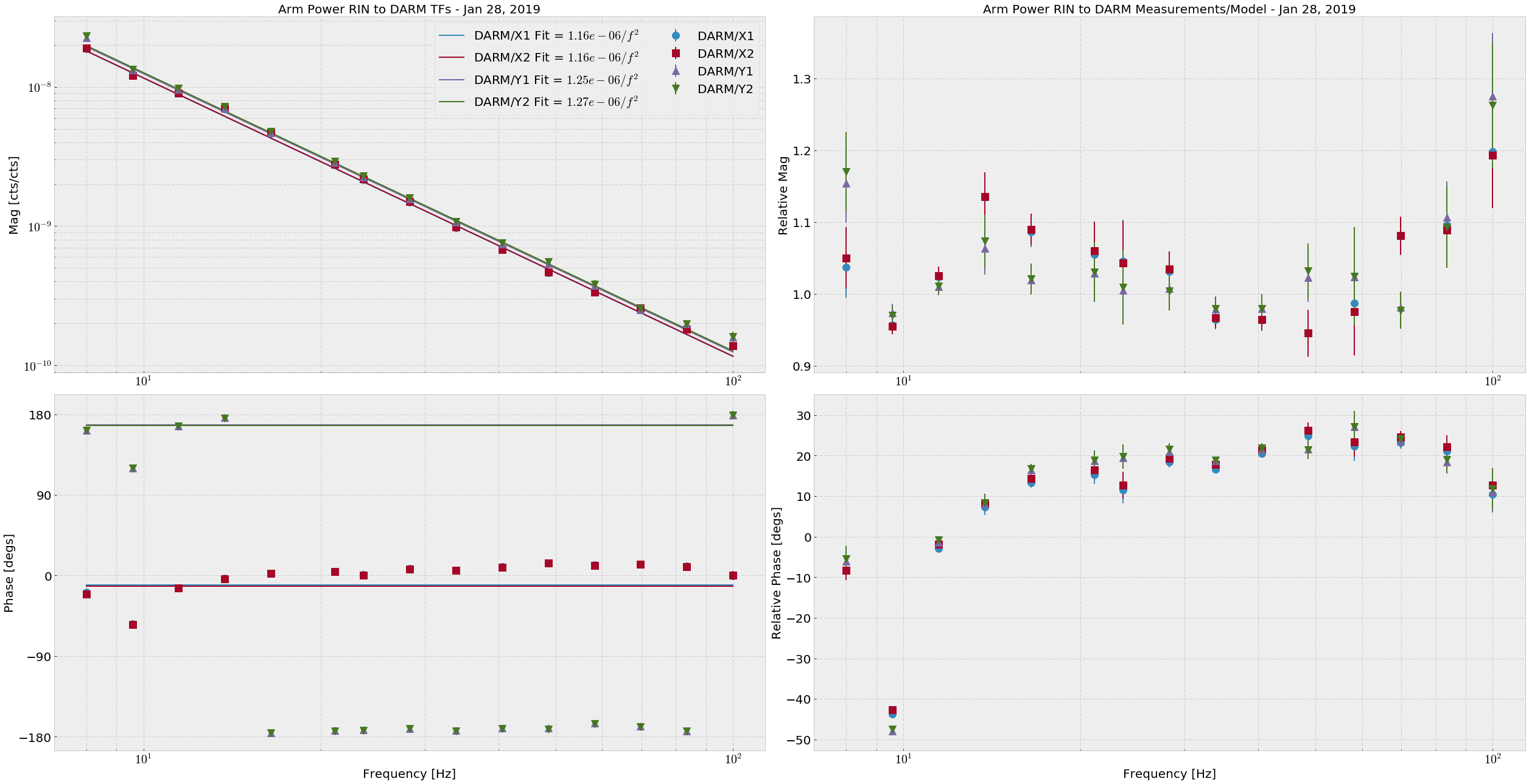
This time I directly fit each of the four Arm Trans QPD RINs (H1:ASC-{X,Y}_TR_{A,B}_NSUM_OUT_DQ) to DARM (H1:CAL-DELTAL_EXTERNAL_DQ), then fit a 1/f2 (attachment one).  The DARM calibration used was the stop gap made by Keita.  The average powers for the RIN calculation are as follows, and are good to +- 300 cts:
Arm Trans QPD counts
XA      145658
XB      191409
YA      207723
YB      221769


This time the math is simpler: 
P_arm = DARM/ArmTransRIN Fit × π2 × m × c


If we look at the different in the arm trans RIN response between the arms, and say that the RIN we see is entirely due to radiation pressure in the arms, we get (DARM/Y)/(DARM/X) = X/Y = 1.08, meaning there may be 8% more light in the X arm than the Y arm.  EDIT: It is actually the Y arm with 8% more light than the X arm.

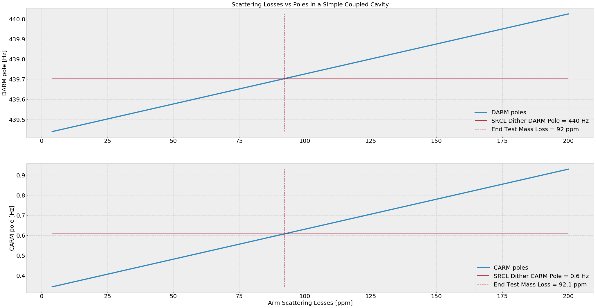
If we calculate the simple power recycling coupled cavity, I find that the estimated average ETM scatter losses are around 92 ppm and the estimated PRG here is 39.  (attachment three)

The measured value of PRG at the time of the measurement is 41.8, and the true input power was 26.5 W (requested was 30W).  If we take these numbers to be true, then our arm gain according to the SRCL dither is 258.
Images attached to this report
Comments related to this report
gabriele.vajente@LIGO.ORG - 15:04, Tuesday 29 January 2019 (46694)

Some simulation work related to this measurement.

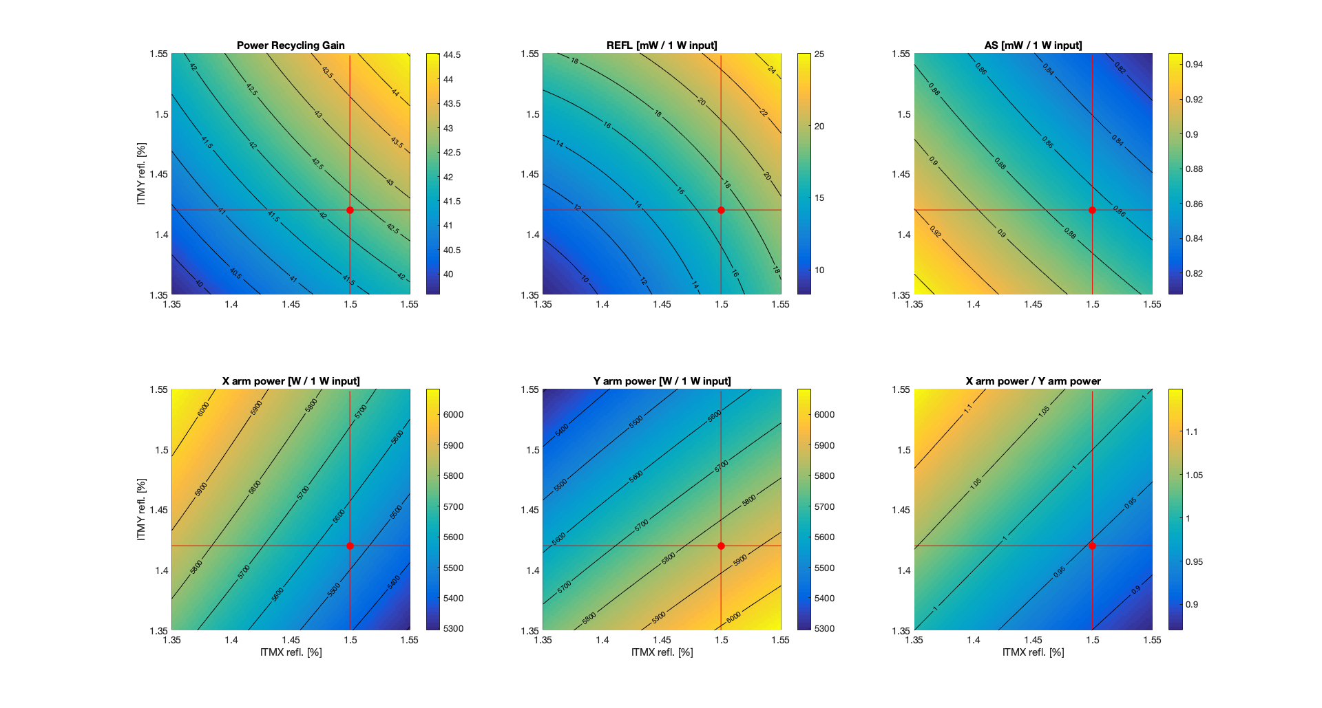
From galaxy, I find that LHO's ITMX (ITM07) has a reflectivity of R_ITMX = 1.50%, while LHO's ITMY (ITM11) has a reflectivity of 1.42%. So there's quite an imbalance there.

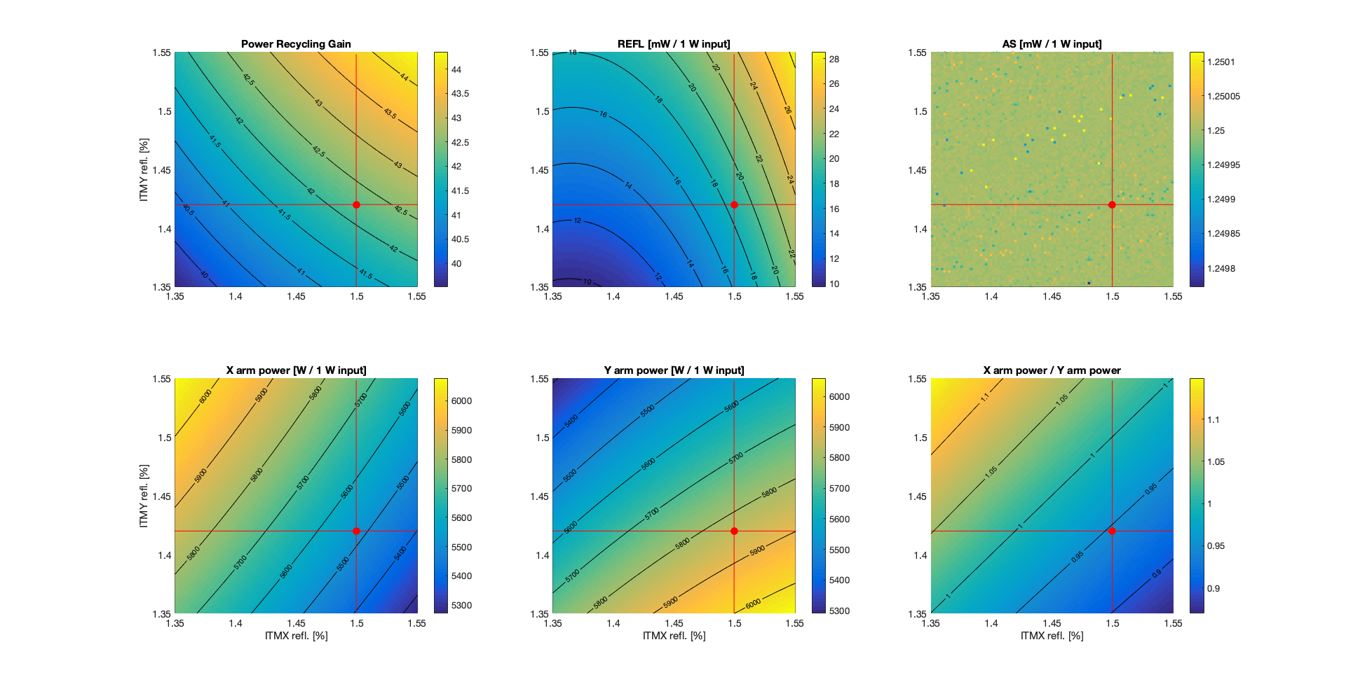
I set up a simple simulation, using only the TEM00 mode, so without including any mismatch. Each arm has about 92 ppm of total round trip losses, following Craig's estimate. The first plot below shows some powers as a function of the two ITM reflectivities. 


The red dot represent the nominal condition, which gives, for 1 W input power

PRG = 42.3
REFL = 17 mW (carrier only, TEM00, perfect matching)
AS = 0.9 mW (carrier only, TEM00m, perfect matching, nominal DARM offset of 1.2e-11 m
XARM = 5536 W
YARM = 5848 W
X/Y = 0.946 [more power in Y arm than X arm]

So there is more power in the Y arm than in the X arm, as one would expect since ITMY has higher reflectivity, so that the Y arm has higher finesse.

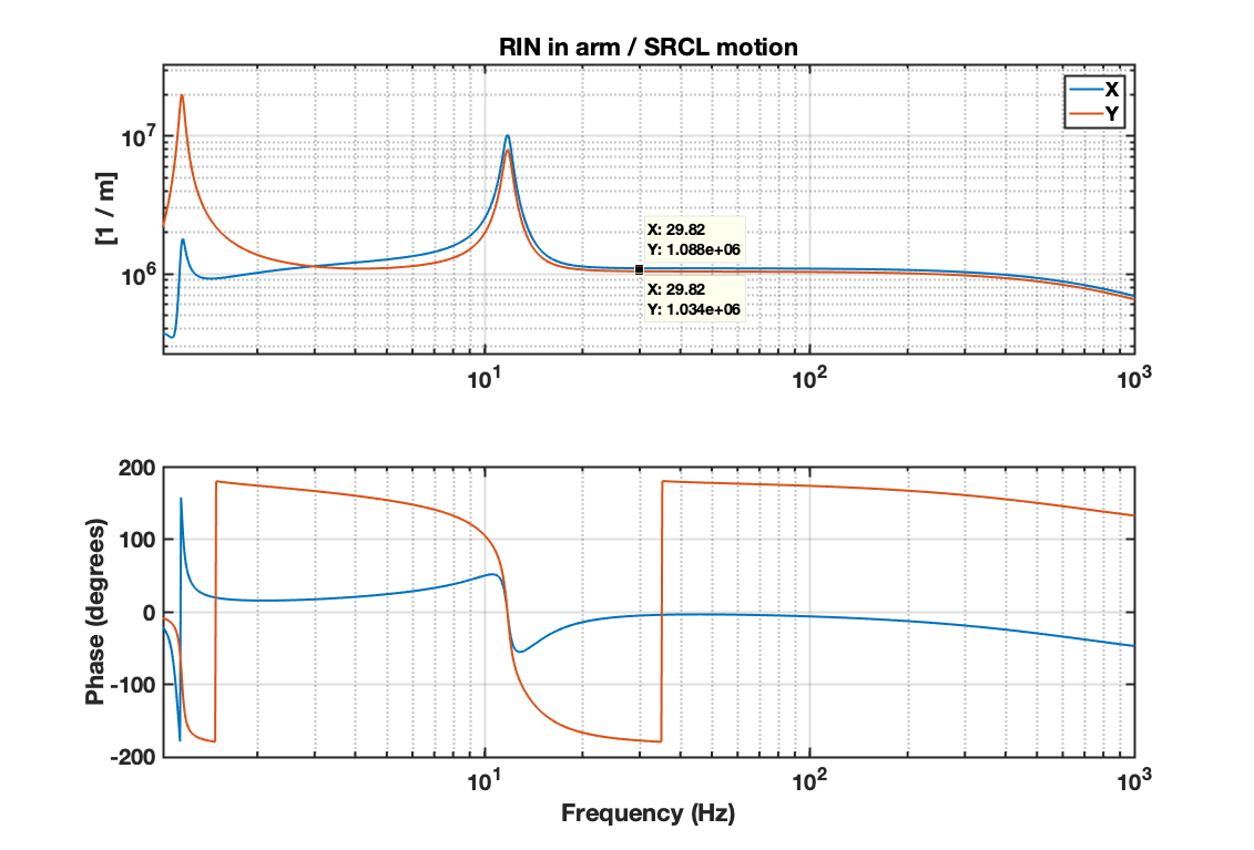
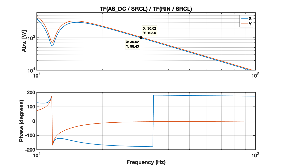
I also tried to reproduce more closely Craig's SRCL dither measurement. So in simulation, I computed the transfer function from SRCL motion to the RIN as measured in transmission of both arms. The plot below shows the simulated transfer functions RIN_ARM / SRCL for X and Y:


The numerical values are

RIN_X / SRCL_z = 1.088e6 /m
RIN_Y / SRCL_z = 1.034e6 /m

so (RIN_X / SRCL_z ) / (RIN_Y / SRCL_z) = 1.052. This is the ratio of powers, since the simulated transfer functions from SRCL to powers are equal for both X and Y, so the transfer functions to RIN are scaled by the inverse of the power. 

Craig's measurement is actually the transfer function DARM / RIN while injecting on SRCL. In simulation, I used the AS port power as a proxy for DARM and computed the transfer functions TF(AS_DC / SRCL) and TF(RIN / SRCL). Then the equivalent of Craig's DARM / X and DARM / Y should be, at 30 Hz,

TF(AS_DC /  SRCL) / TF(RIN_X / SRCL) = 98.4 W
TF(AS_DC /  SRCL) / TF(RIN_Y / SRCL) = 103.6 W

and the frequency dependency is shown in the plot below (1/f^2 as expected).


So the equivalent of Craig's ratio (DARM / Y) / (DARM / X) should be 

[ TF(AS_DC /  SRCL) / TF(RIN_Y / SRCL) ] / [ TF(AS_DC /  SRCL) / TF(RIN_X / SRCL) ] = 103.6 / 98.4 = 1.053

which is greater than one as in Craig's measurement, but corresponds to the ratio POWER_Y / POWER_X. 

So the conclusion from my simulation is that the ITM different reflectivities gives a ratio of TF (as measured by Craig) greater than 1, which corresponds to higher power in the Y arm than in the X arm (the opposite of what Craig's concluded...)


Images attached to this comment
craig.cahillane@LIGO.ORG - 17:17, Tuesday 29 January 2019 (46698)
I didn't know that the ITMs were not the same reflectivity.  This is absolutely mind-blowing information.
I reported higher arm power in the Y arm before, from the HEPI measurement.  
The RIN/SRCL TF corresponds to Equation 12 here.  It is not dependent on the arm power at all, but rather the optical response γ of each arm to the SRCL dither.
Also, the DARM/RIN TF in Equations 20 and 21 also indicate that DARM/RIN = 4*Parm/(m c ω2), so I made a mistake last night.
gabriele.vajente@LIGO.ORG - 20:41, Tuesday 29 January 2019 (46700)

Good that the measurement and the prediction agree that there is more power in Y than in X.

Now we have to figure out why the measurement gives 8% imbalance while from the ITM reflectivities we only get 5%.

gabriele.vajente@LIGO.ORG - 16:50, Wednesday 30 January 2019 (46710)

Updated simulation: 

  1. added higher order modes (n+m<=10), measured test mass radii of curvature
  2. locked DARM to have an AS power that corresponds to 20 mA at 26 W input power (1.25 mW on the OMC transmission for 1 W input)

No change in the conclusions. Same imbalance of the arm powers as before (about 5%) 


Images attached to this comment
gabriele.vajente@LIGO.ORG - 09:43, Thursday 31 January 2019 (46720)

Adding the substrate lenses do not change significantly the power imbalance. 

ITMX: static lens -310km, thermal lens +770km
ITMY: static lens +570kn, thermal lens +350km

gabriele.vajente@LIGO.ORG - 14:46, Friday 01 February 2019 (46749)

Follow up to the discussion at today's commissioning call.

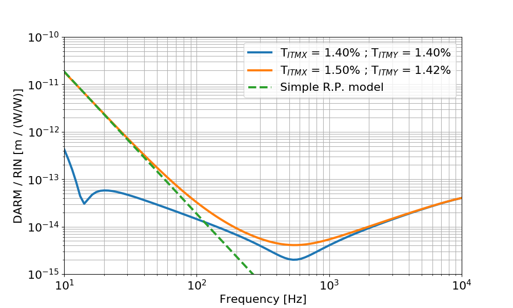
I computed the transfer function from laser relative intensity noise at the IFO input (called rin below) to DARM (calibrated in meters). 

The input power is 26 W, and the round trip losses are adjusted to get a recycling gain of about 42. In the blue trace below, the two ITMs have the same reflectivity, equal to the nominal value of 1.4%. In the orange trace the two ITMs have different reflectivities, ITMX = 1.50% and ITMY = 1.42%, from the measured values from galaxy. This is the same configuration used in the other simulations, that gives a 5% power imbalance. 

The dashed green curve is a simple radiation pressure model according to the equation below:


where RIN_arm / RIN_input is basically the double cavity pole (since input RIN is filtered by this transfer function. I used the simulated result), Delta P is the DC power difference in the arms ( Y - X = 7.7 kW) and m is the mirror mass. This matches quite well the low frequency simulation.


Using the simulated transfer function I can see what level of RIN at the IFO input would limit the sensitivity. It turns out that one needs a RIN of about 5e-6 (W/W)/rHz. 


Images attached to this comment
gabriele.vajente@LIGO.ORG - 11:18, Monday 04 February 2019 (46759)

I found a mistake in my previous RIN simulation (many thanks to Matt Evans for spotting the inconsistency). Here's the correct results and plots.

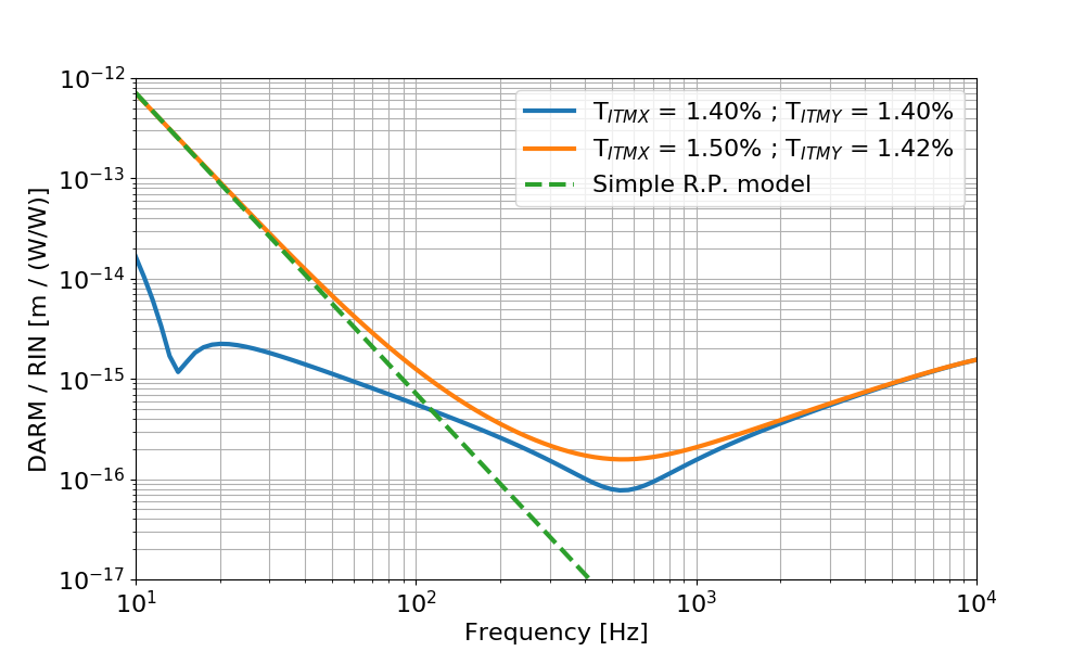
Follow up to the discussion at today's commissioning call.

I computed the transfer function from laser relative intensity noise at the IFO input (called rin below) to DARM (calibrated in meters). 

The input power is 26 W, and the round trip losses are adjusted to get a recycling gain of about 42. In the blue trace below, the two ITMs have the same reflectivity, equal to the nominal value of 1.4%. In the orange trace the two ITMs have different reflectivities, ITMX = 1.50% and ITMY = 1.42%, from the measured values from galaxy. This is the same configuration used in the other simulations, that gives a 5% power imbalance. 

The dashed green curve is a simple radiation pressure model according to the equation below:


where RIN_arm / RIN_input is basically the double cavity pole 0.6Hz/fr (since input RIN is filtered by this transfer function), Delta P is the DC power difference in the arms ( Y - X = 7.7 kW) and m is the mirror mass. This matches quite well the low frequency simulation.

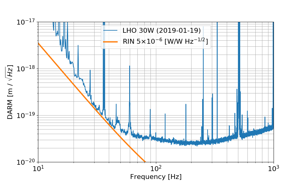
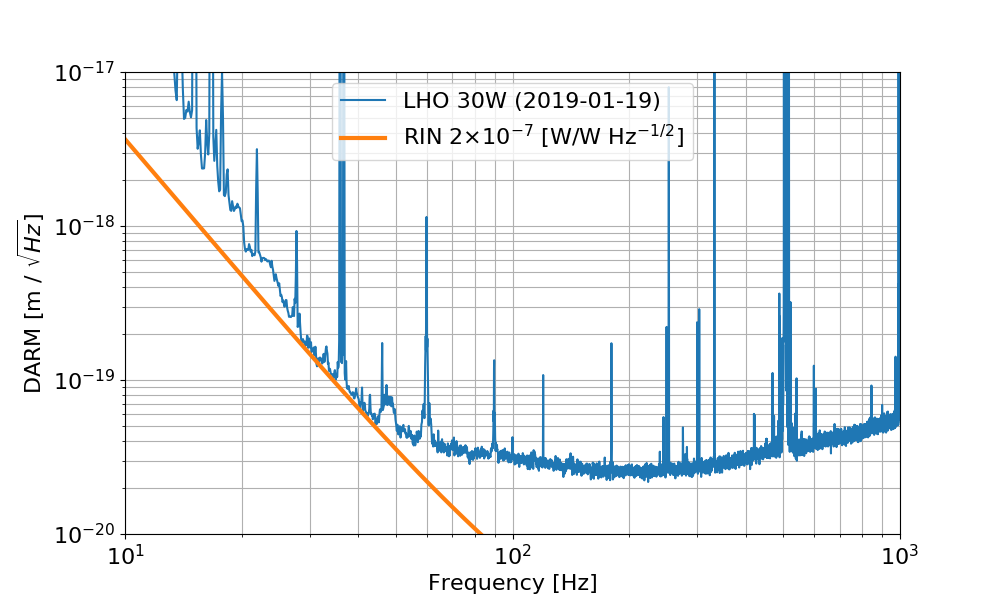
Using the simulated transfer function I can see what level of RIN at the IFO input would limit the sensitivity. It turns out that one needs a RIN of about 2e-7 (W/W)/rHz


Images attached to this comment
matthew.evans@LIGO.ORG - 15:35, Monday 04 February 2019 (46772)

Doesn't this 2e-7 /rtHz RIN seem dangerously close to the measured value at 30Hz?

sheila.dwyer@LIGO.ORG - 20:49, Monday 04 February 2019 (46780)

The intensity noise projection in the noise budget is made by injecting into the ISS second loop.  It shows that the intensity noise is not close to DARM.  45828


H1 SYS (CAL, GRD, INJ, ISC)
jameson.rollins@LIGO.ORG - posted 14:47, Tuesday 15 January 2019 - last comment - 15:11, Thursday 07 February 2019(46428)
initail ODC removal work

ODC removal (as per ECR 12045) has begun.  Summary:

Detailed front end changes:

Further removal of ODC from the rest of the system (ISC, SUS, PEM, etc.) is deferred to later maintenance. 

Comments related to this report
keita.kawabe@LIGO.ORG - 17:17, Tuesday 15 January 2019 (46447)

Following models were changed to remove ODC completely and compiled but not installed. Deferred to another opportunity.

h1ascimc (1 IPC sender (PCIE) and an entire ODC block were removed, doesn't use the library, one less fast channel on the frame)

h1pslpmc (1 sender (SHMEM) as well as an entire ODC block was removed from h1 model, ODC-related things were purged from the library, no change in fast channels)

p1psliss (2 receivers (SHMEM) for FSS and PMC as well as two ODC blocks were removed from h1 model, ODC-related things were purged from the library, one less fast channel on the frame)

h1pslfss (1 sender (SHMEM) as well as an ODC block were removed from h1 model, ODC-related things were purged from the library,  no change in fast channels)

h1tcscs (1 sender (SHMEM) as well as an ODC block were removed from h1 model, ODC-related things were purged from the library, one less fast channel on the frame)

h1iscex (done by Jamie, no change in fast channels)

h1alsex (1 sender (SHMEM) as well as an ODC block were removed from h1 model, doesn't use library, one less fast channel on the frame)

h1alsey (1 sender (SHMEM) as well as an ODC block were removed from h1 model, doesn't use library, one less fast channel on the frame)

h1lsc (1 sender (PCIE) and an ODC block are removed from the h1 model, doesn't use library, one less fast channel on the frame)

h1omc (1 sender (PCIE) as well as an ODC block were removed from h1 model, ODC-related things were purged from the library, one less fast channel on the frame)

h1pemex (1 sender (SHMEM) as well as an ODC block were removed from h1 model, doesn't use library, no change in fast channels)

h1pemey (1 sender (SHMEM) as well as an ODC block were removed from h1 model, doesn't use library, no change in fast channels)

all SEI models at the end stations (done by JeffK)

Following models are yet to be changed.

all sus models (TBD by JeffK)

keita.kawabe@LIGO.ORG - 13:17, Tuesday 22 January 2019 (46576)CDS, DetChar, SYS

Update on Jan 22

During the maintenance on Jan22, the following models without ODC were installed.

h1lsc, h1ascimc, h1omc, h1iscex, h1alsex, h1alsey, h1tcscs, h1pemex, h1pemey.

(h1asc was updated and installed for something unrelated to ODC.)

Remaining frontends that are yet to be replaced with new ones without ODC:

All SUS (models are yet to be changed/compiled).

All end station SEI (models are ready).

h1pslpmc, h1pslfss, h1psliss (models are ready).

Remaining frontends that will be changed again after new HW injection infrastructure is confirmed to work by transient injection group(s):

h1calex (model is yet to be done, PINJX will be completely removed).

h1odcmaster itself (this will be retired).


keita.kawabe@LIGO.ORG - 14:35, Monday 04 February 2019 (46769)

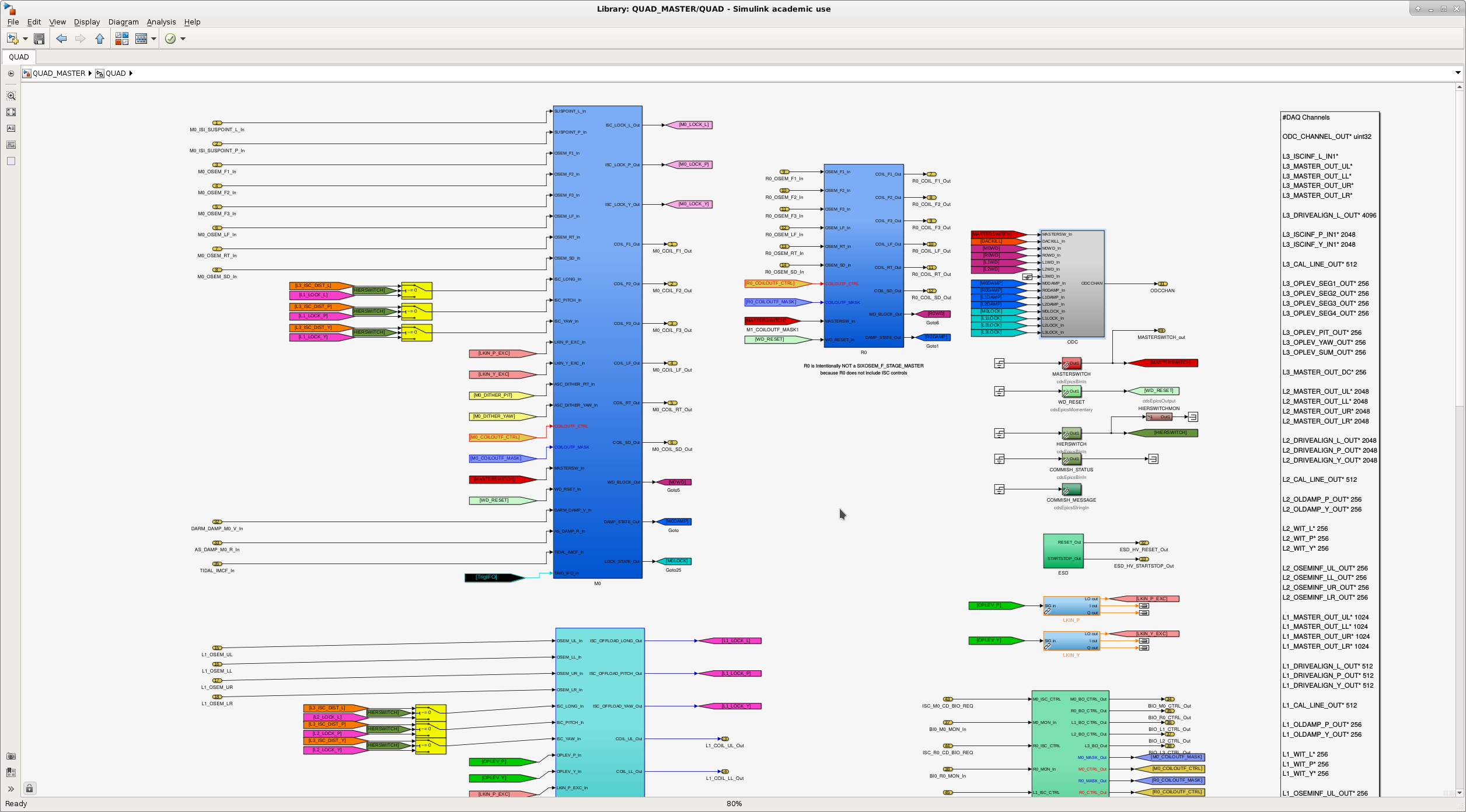
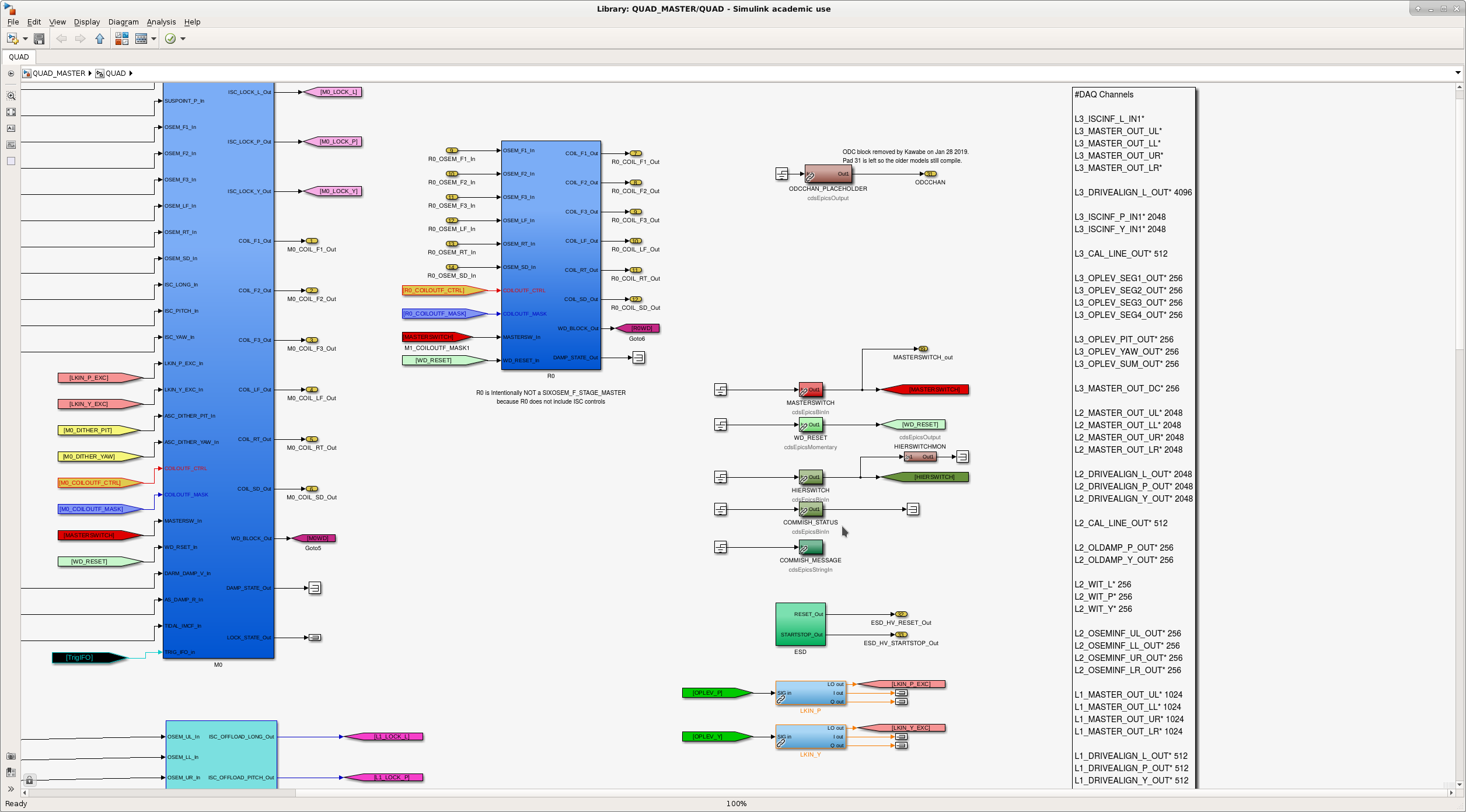
Update Feb/04/2019

All SUS models were modified to remove ODC, compiled successfully, but not installed. These are:

h1susetmx, h1susetmy, h1susitmx, h1susitmy, h1susbs, h1suspr3, h1suspr2, h1susprm, h1sussr3, h1sussr2, h1sussrm, h1susmc1, h1susmc2, h1susmc3, h1susomc, h1susopo, h1susim (and h1sustmsx and tmsy and h1sushtts on Feb/05/2019)

One PCIE IPC sender and one fast channel were removed per each model, as well as many EPICS channels. One new EPICS channel (ODCCHAN_PLACEHOLDER) was added per each model.

Library parts (QUAD_MASTER, QUAD_ITM_MASTER, BSFM_MASTER, HSTS_MASTER, HLTS_MASTER, OMCS_MASTER, OPOS_MASTER) are still compatible with old models, so if you want to compile any of old sus models with the new library you can. In that case ODC IPC will be plugged to zero.

Attached are typical before/after view of the library parts.

Images attached to this comment
keita.kawabe@LIGO.ORG - 16:38, Tuesday 05 February 2019 (46803)

Boo. I just assumed that MC1, MC2 and MC3 all use HSTS_MASTER library part, but MC2 actually uses MC_MASTER part. I only edited HSTS_MASTER and individual model (h1susmc1, 2, 3).

As a result, ODC was not completely removed out of h1susmc2. This is going to be fixed in the next opportunity.

rahul.kumar@LIGO.ORG - 15:11, Thursday 07 February 2019 (46852)CDS, SUS
Keita and Rahul

Keita showed me how to make changes to the front end model of SUS. We made changes to MC_MASTER library parts to remove ODC. We complied h1susmc2 successfully, however we didn't install it. 
Displaying reports 43261-43280 of 88648.Go to page Start 2160 2161 2162 2163 2164 2165 2166 2167 2168 End