Displaying reports 43301-43320 of 88618.Go to page Start 2162 2163 2164 2165 2166 2167 2168 2169 2170 End
Reports until 10:38, Wednesday 30 January 2019
H1 SUS
jenne.driggers@LIGO.ORG - posted 10:38, Wednesday 30 January 2019 (46707)
Test mass actuators balanced to each other

[Satoshi, Jenne]

This morning we balanced the test mass actuators to each other (ETMX to ETMY and ITMX to ITMY) and then balanced the actuation of the ITMs relative to the ETMs for soft / hard decoupling.  Unfortunately this didn't help the mysterious phase situation in DHARD_P at high power.

To balance the ETMs to eachother, we used the ASC oscillator that goes through the output matrix, and pushed on the ETMs in pitch with coefficients +1*ETMX and +1*ETMY to actuate in common pitch. The line was at 15.9Hz with an amplitude of 30k counts.  We then adjusted the gains in the L2 LOCK filter banks (H1:SUS-ETMX_L2_LOCK_P_GAIN) to minimize this line in AS_45_Q_Pit.  This oscillation was stopped, and then the output matrix was changed to push on the ITMs in pitch, again with coeffs +1 and +1.  For the yaw balancing, we repleated the same test, but pushed +1*ETMX and -1*ETMY to be actuating in common yaw.  Similar +1,-1 coeffs for the ITMs in yaw. 

The L2 coefficients for the test masses are different from 1 by about 5%, so not very much, and also not very different from what they used to be.

Once that was done, we then actuated in DSOFT (again using the ASC oscillator, at 15.9Hz), and adjusted the elements of DSOFT to minimize the line in AS_45_Q.  For pitch, the elements changed from 0.87 to 0.74.  For yaw, the elements changed from 0.87 to 0.72.  

The DHARD OLG at 2W didn't change when we changed the output matrix elements.  Also, when we powered up to 20W, we still see the not so great mysterious phase situation, so this balancing did not magically fix that stuff.  We are able to power up to 30W and do most of lownoise_ASC, but as has been true in the past few days, the DHARD_P lines of code are commented out.  Trying to implement them by hand (lowering the gain, and engaging a cutoff) made the 1.1Hz motion start to ring up, so we reverted them back to the high bandwidth situation.  Frustrating.
 

H1 SQZ (SQZ)
nutsinee.kijbunchoo@LIGO.ORG - posted 10:28, Wednesday 30 January 2019 (46706)
SQZ/ASQZ measurement with L1 locking scheme

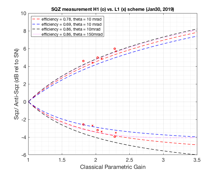
Got enough squeezing to move on to injecting it into the IFO I think. Plot below shows sqz/asqz data points from H1 locking scheme (o) vs. L1 locking scheme (x). 20dB attenuator was in during H1 scheme measurement and 10dB attenuator was in during L1 scheme measurement. Similar CLF power were used (~1uW transmitted). The nlg calculation has taken dark noise into account.


Funny thing I observed was that if I increase CLF input power by a factor of 6 where I know I should have cleared the sensing noise, while HD didn't saturate I couldn't get more than 2.5 dB of squeezing at nlg of 2.285 (asqz 5.86). I tried increasing CLF and LO gain and non of them helped. 


Noise budget coming up next.


Images attached to this report
H1 CDS (DAQ)
david.barker@LIGO.ORG - posted 09:37, Wednesday 30 January 2019 (46705)
CDS maintenance, Tuesday 29th January 2019

Late report for yesterday's light maintenance day.

h1susb123 DAC drive problem

Richard, Dave:

h1iopsusb123 stopped driving its DACs due to a timing glitch. All models on h1susb123 were restarted to clear the problem.

h1sysecatc1plc2sdf unresponsive, restarted

Dave:

Over the weekend I found that h1sysecatc1plc2sdf had become unresponsive. I restarted this 'faux' model on h1ecatmon0 which cleared the problem.

H1 General
edmond.merilh@LIGO.ORG - posted 08:34, Wednesday 30 January 2019 (46703)
Shift Transition - Day

TITLE: 01/30 Day Shift: 16:00-00:00 UTC (08:00-16:00 PST), all times posted in UTC
STATE of H1: Preventive Maintenance
OUTGOING OPERATOR: None
CURRENT ENVIRONMENT:
    Wind: 3mph Gusts, 1mph 5min avg
    Primary useism: 0.77 μm/s
    Secondary useism: 0.26 μm/s
QUICK SUMMARY:

5.4 Earthquake on Central East Pacific Rise has BLRM up to 1um. Nothing tripped. IFO locking as normal.


H1 ISC
sheila.dwyer@LIGO.ORG - posted 02:04, Wednesday 30 January 2019 (46701)
DHARD P investigations today, some 9 MHz noise checks

Marie, Georgia, Arnaud, Craig Jenne Sheila Adam Rich

Summary:

The DHARD P loop is stable right now, after reducing the gain of all AS QPD loops.  We still have the phase evolution that we don't understand, but we are able to reduce the gain of DHARD and be stable with the cut off on. 

Engaging dither loops with lower bandwidth soft

Georgia reduced the bandwidth of the AS centering loops for yaw so that they are around 0.1 Hz, similar to pitch.  

The first time that we tried to engage the dither loops with these lower bandwidth soft loops, we lost lock because the dither loops moved pretty far and the centering loops didn't keep up.  The next time we engaged the ITMY to PRM dither loops first, which brought the ETM dither error signals closer to zero so that we could engage them as well.  Georgia edited the ENGAGE SOFT loops guardian state so that it should engage the ITMY to PRM dither first, then check for the error signals to go below a threshold before engaging the ETM dither loops.

We changed the output matrix for the ETM dither loops to be 1 for the ITMs and 0.78 for the ETMs.  This is what LLO did to move the spots only on the ETMs.  This should help to decouple the ETM loops from the ITM dithers.  

DHARD P

We were having a 1Hz ring up for any gains less than -60 when we first locked, with 30W input and the RPC gain at -1.2.  We eventaully reduced the gain of SRC2 P by a factor of 15 (from 15 to 1).  Now we were able to reduce the DHARD P gain to -30, which is the nominal value for low noise, and engage the 17Hz LP.  

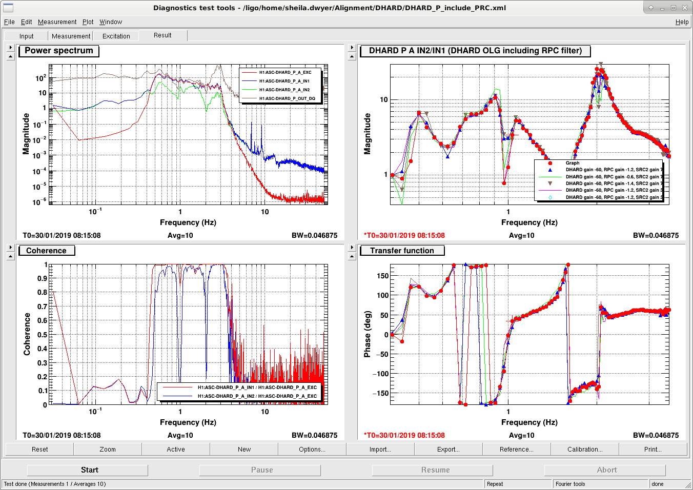
The problem we have is the 0 phase at 1 Hz, and there is a dip in the gain at that frequency for some reason.  We could change the dip in the gain by changing the RPC gain, but only to make it deeper.  We also found that reducing the gain of SRC2 P (AS_C to SR2) made the dip deeper.  This allows us to reduce the gain because the unstable point at 1 Hz drops below unity gain.  Screen shot attached shows the OLG measured from the blend, this includes the radiation pressure compensation in the measurement.  The measurement shows the loop gain once before we reduced it and turned on the low pass.  We have not put the changes to SRC2P or the gain changes for DHARD P into the guardian. 

When we have a DARM offset there are the terms that contribute to the ASQ and QPD signals:

ASQ signal: 45_{00}*Carrier_{00} + 45_{00}*Carrier_{10}  The first term is due to the DARM offset, and is sensitive to motion of the SRC cavity axis or the OMs.  The second term is the DHARD signal

QPD signals (AS_A, B, C DC signals) 45_{00}*45_{00}+C_{00}*C_{00} + C_{00}*C{10}+45_{00}*45_{10}   The second term is due to the DARM offset, and is sensitive to the SRC cavity axis and the OMs (on AS A and B).  The third term is also due to the DARM offset and contains DHARD signal.  

This means that when we have a DARM offset, there is a cross coupling between the QPD loops and the DHARD loop, which depends on the DARM offset. This means that both the SRC2 loop and the AS centering loops can have an impact on the stability of the DHARD loop, and vice versa.  

DARM offset/ 9 MHz increase test:

We also took some measurements that we have been wanting to do for a while to understand better where the 9 MHz noise is in DARM, will post results soon.  

Images attached to this report
H1 SEI
arnaud.pele@LIGO.ORG - posted 02:02, Wednesday 30 January 2019 - last comment - 14:02, Wednesday 30 January 2019(46702)
HAM3 ISI Ry loop off for testing

I tried more tests to investigate the 1.1Hz HAM3-ISI line, following up on Jim and Hugh's effort. I am keeping track of the tests done so far in this document. One of the ways to remove the peak is to turn off the Ry isolation loop, at the expense of low-frequency horizontal motion, see the X motion before vs after, or Ry motion before vs after.

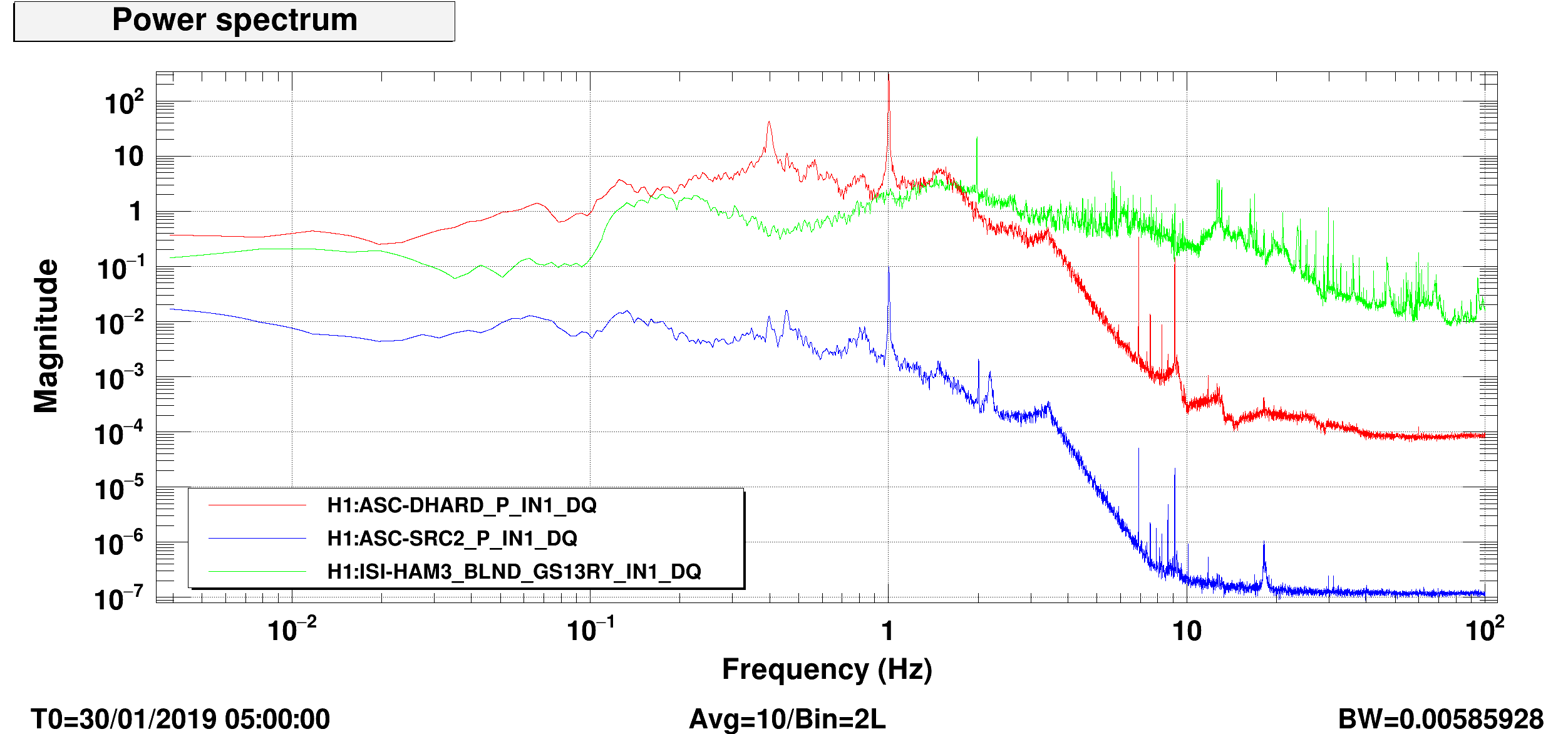
With low enough useism, the ifo was locked in this configuration to test if this would change the 1Hz ASC behavior. The two problems look independent since we found ASC to be still marginally stable around 1Hz but with no peak present on the ISI, see attached screenshot.

Will keep investigating.

Images attached to this report
Comments related to this report
jim.warner@LIGO.ORG - 14:02, Wednesday 30 January 2019 (46708)

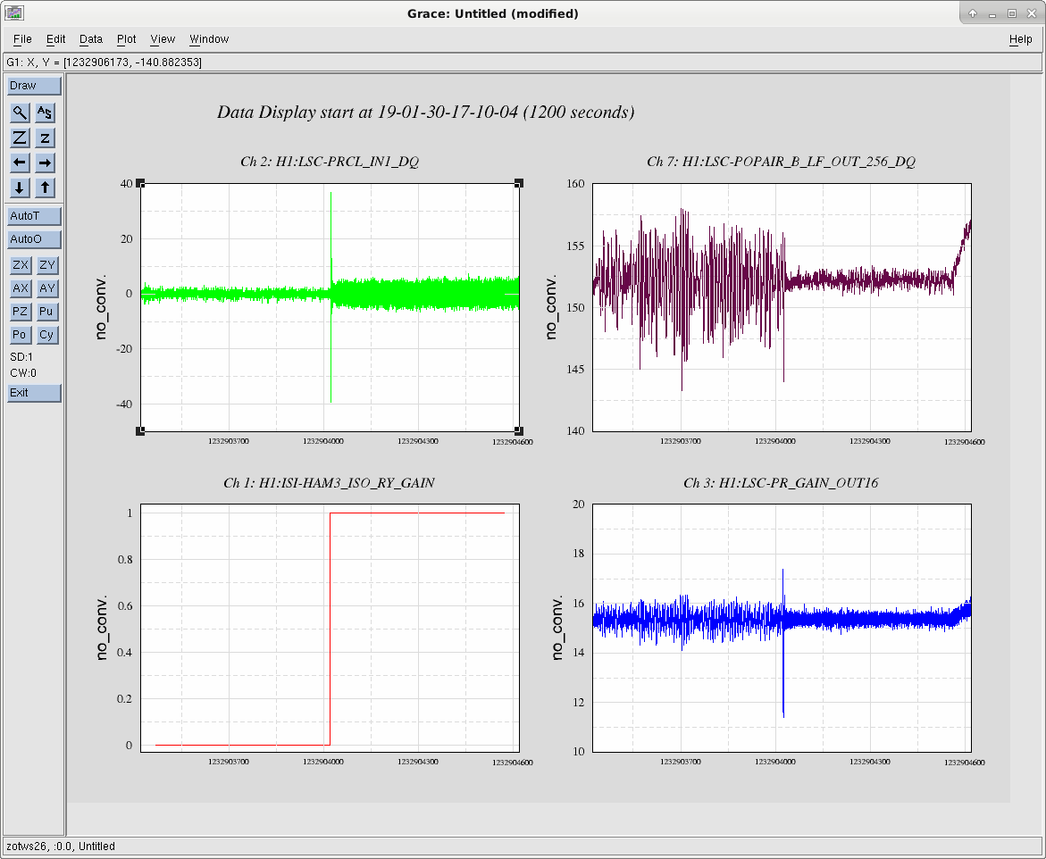
This morning, I was looking at some other stuff on HAM3 and trying to clean up SDF, when I must have misclicked and turned the gain back to 1 on the RY loop. Because Arnaud had disengaged the boost, the ISI stayed isolated, but it glitched some of the IFO signals. It also made an immediate improvement in the PR recycling gain, making it much quieter, but this brought back the 1.1hz feature on the ISI. The take away is that leaving the RY loop off is good for PRCL, bad for the PR gain (when the soft loops are off), but this may only be true because the microseism is low right now. 

First attached image are timeseries of PRCL, POPAIR_B_LF, the HAM3 RY loop gain and LSC_PR_GAIN. The glitch in the middle of each window is me accidentally turning on the RY loop, PRCL immediately gets noisy, but POPAIR_B gets quiet.

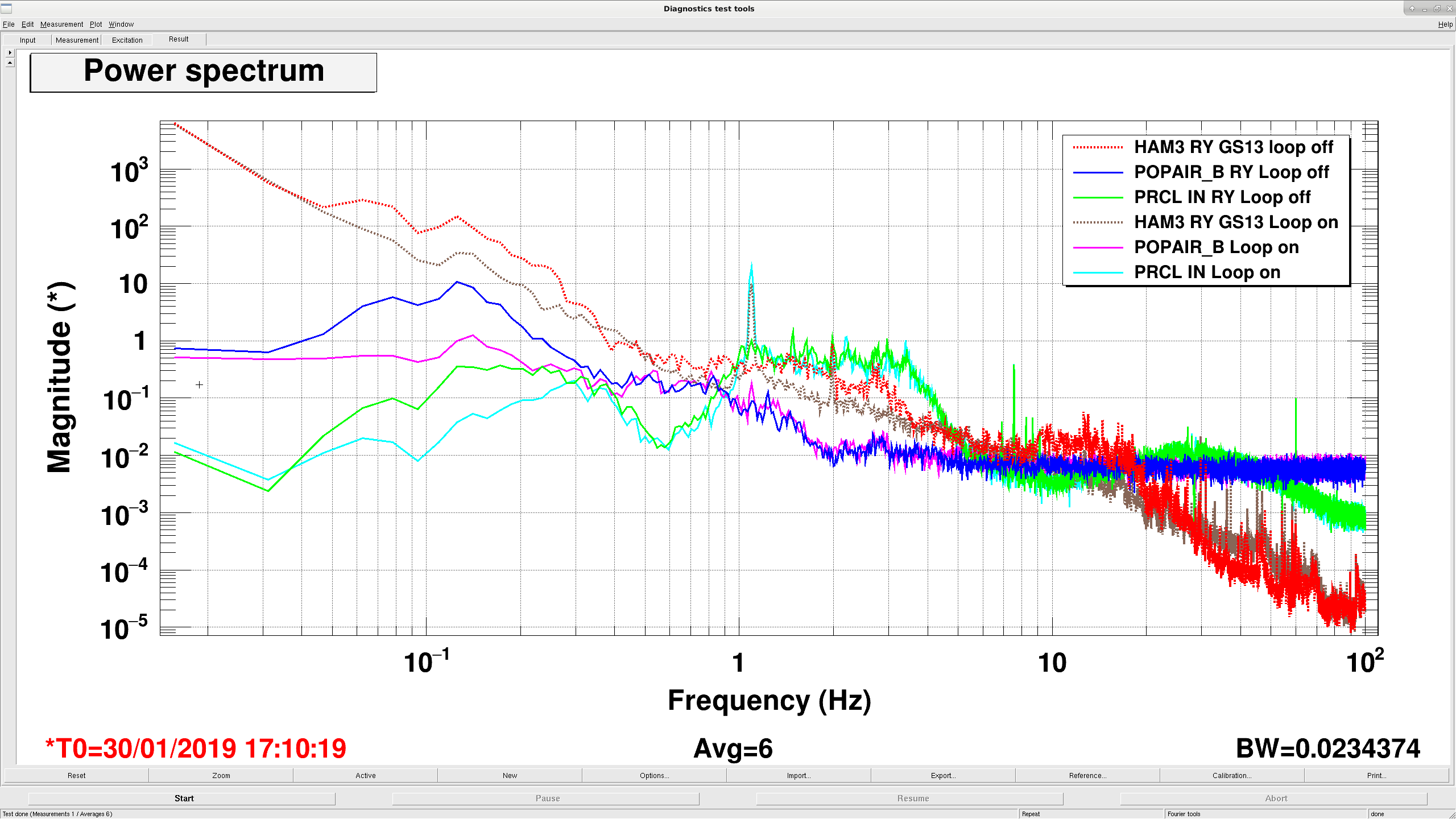
Second plot is asds comparing before and after. The dashed lines are the HAM3 RY gs13s, blue and pink are POPAIR_B, green and light blue are PRCL. With the RY loop off, POPAIR_B is dominated by the extra .05-.3hz extra motion in HAM3 RY. With the loop on, this extra motion goes away, but PRCL is dominated by the 1.1hz peak. 

Images attached to this comment
H1 SQZ (SQZ)
nutsinee.kijbunchoo@LIGO.ORG - posted 18:25, Tuesday 29 January 2019 (46699)
New medm screen for L1 locking scheme guardian

I made another screen to host guardian nodes for the original locking scheme (labeled 'L1'). 'H1' indicate the locking scheme we have been using until recently (laser follows the OPO). Both can be found under SQZ GUARDIANS OVERVIEW L1 and H1 scheme. Two more Guadian nodes for the L1 scheme is coming. OPO_L1 and CLF_L1 works. SHG hasn't changed (CLF hasn't changed either, I made a new one for managing purpose).

Images attached to this report
H1 AOS (ISC)
craig.cahillane@LIGO.ORG - posted 17:42, Tuesday 29 January 2019 - last comment - 20:49, Monday 04 February 2019(46683)
What is the arm power 2
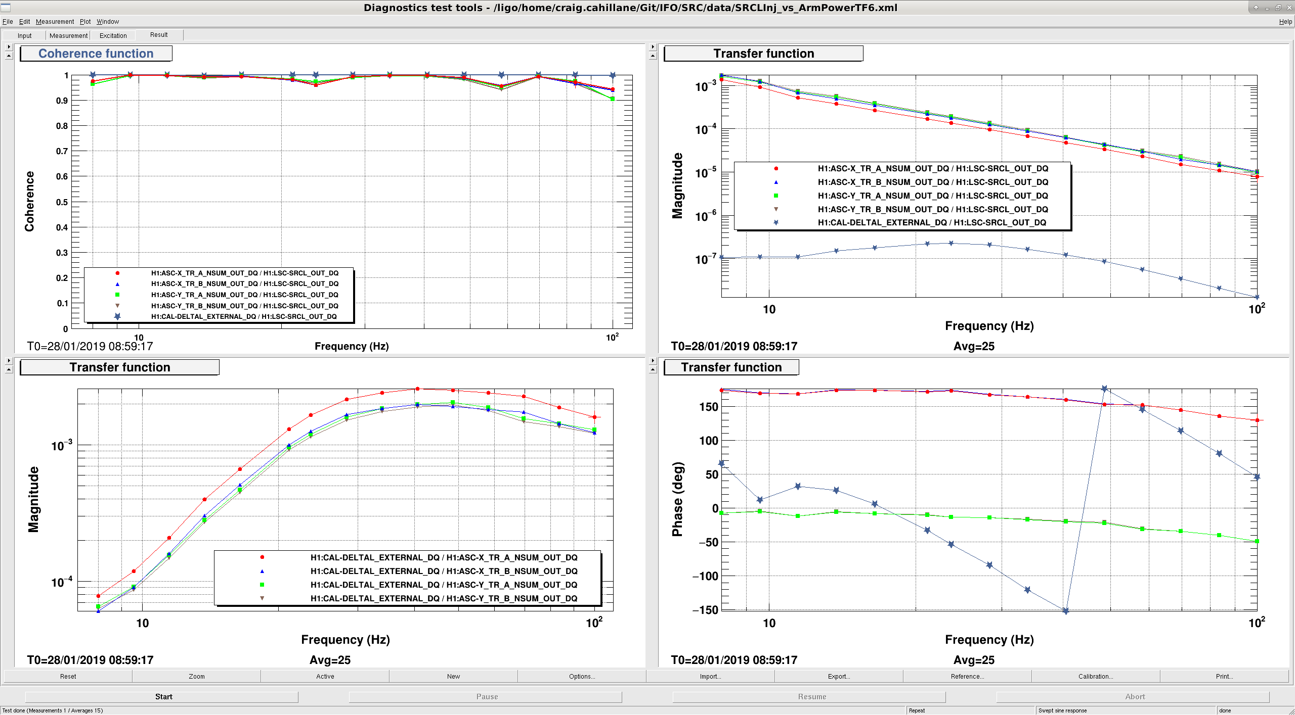
On January 8th I tried to measure the average arm power by dithering SRCL.  Last night I did it again, this time with better TFs taken simultaneously.

Average Arm Power = 143.0 +- 5.8 kW

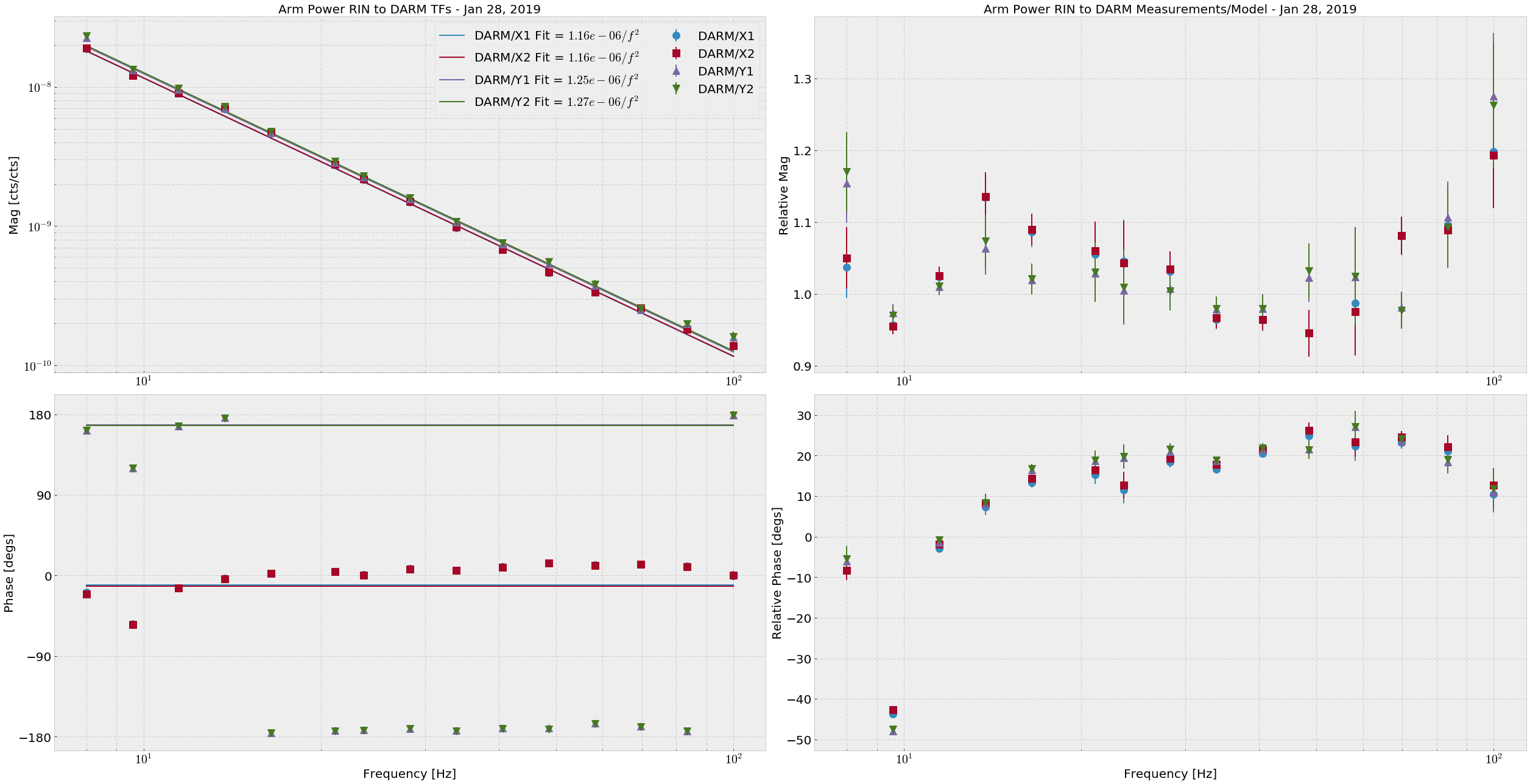
This time I directly fit each of the four Arm Trans QPD RINs (H1:ASC-{X,Y}_TR_{A,B}_NSUM_OUT_DQ) to DARM (H1:CAL-DELTAL_EXTERNAL_DQ), then fit a 1/f2 (attachment one).  The DARM calibration used was the stop gap made by Keita.  The average powers for the RIN calculation are as follows, and are good to +- 300 cts:
Arm Trans QPD counts
XA      145658
XB      191409
YA      207723
YB      221769


This time the math is simpler: 
P_arm = DARM/ArmTransRIN Fit × π2 × m × c


If we look at the different in the arm trans RIN response between the arms, and say that the RIN we see is entirely due to radiation pressure in the arms, we get (DARM/Y)/(DARM/X) = X/Y = 1.08, meaning there may be 8% more light in the X arm than the Y arm.  EDIT: It is actually the Y arm with 8% more light than the X arm.

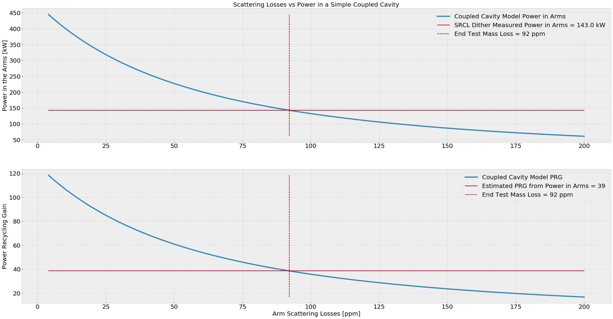
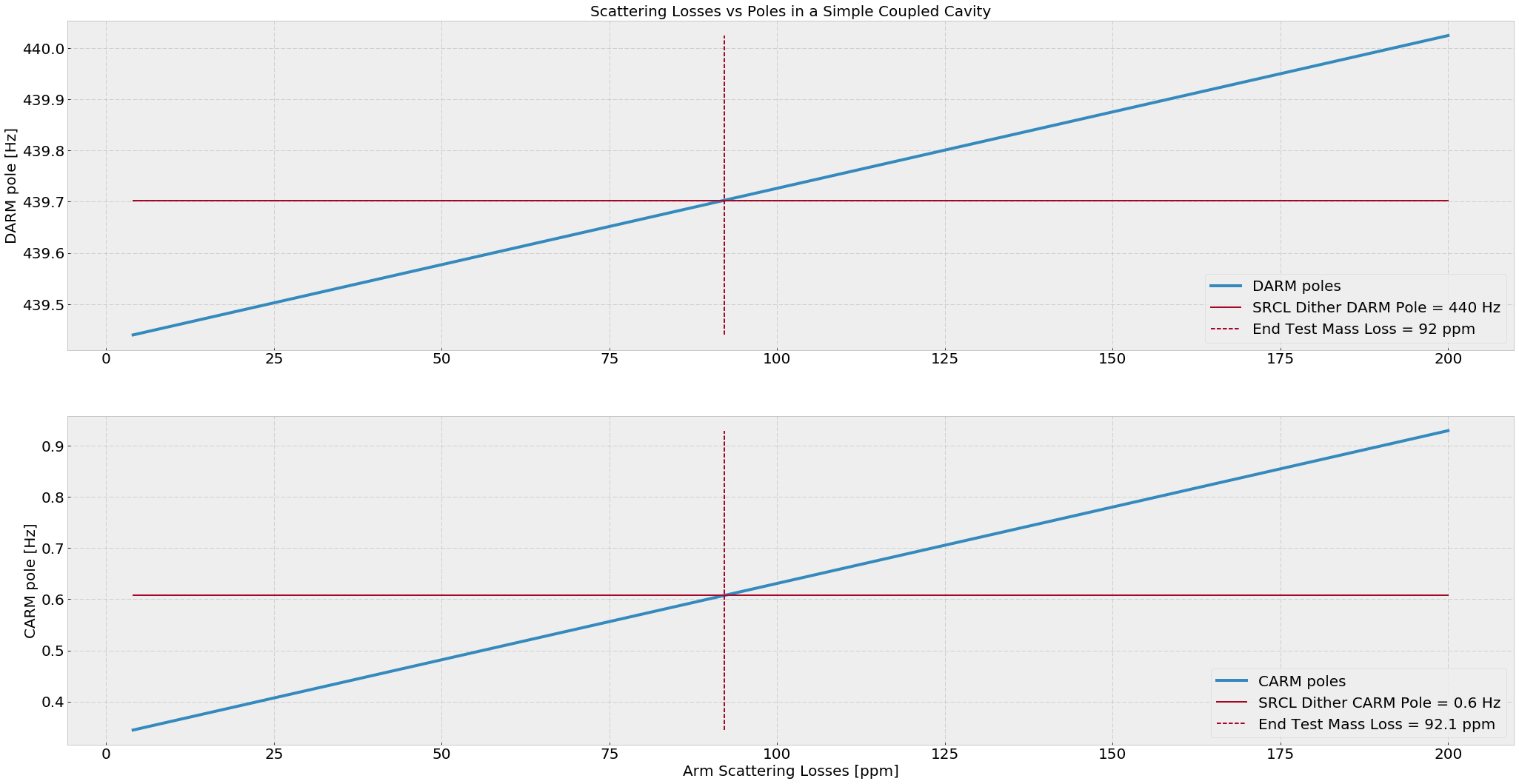
If we calculate the simple power recycling coupled cavity, I find that the estimated average ETM scatter losses are around 92 ppm and the estimated PRG here is 39.  (attachment three)

The measured value of PRG at the time of the measurement is 41.8, and the true input power was 26.5 W (requested was 30W).  If we take these numbers to be true, then our arm gain according to the SRCL dither is 258.
Images attached to this report
Comments related to this report
gabriele.vajente@LIGO.ORG - 15:04, Tuesday 29 January 2019 (46694)

Some simulation work related to this measurement.

From galaxy, I find that LHO's ITMX (ITM07) has a reflectivity of R_ITMX = 1.50%, while LHO's ITMY (ITM11) has a reflectivity of 1.42%. So there's quite an imbalance there.

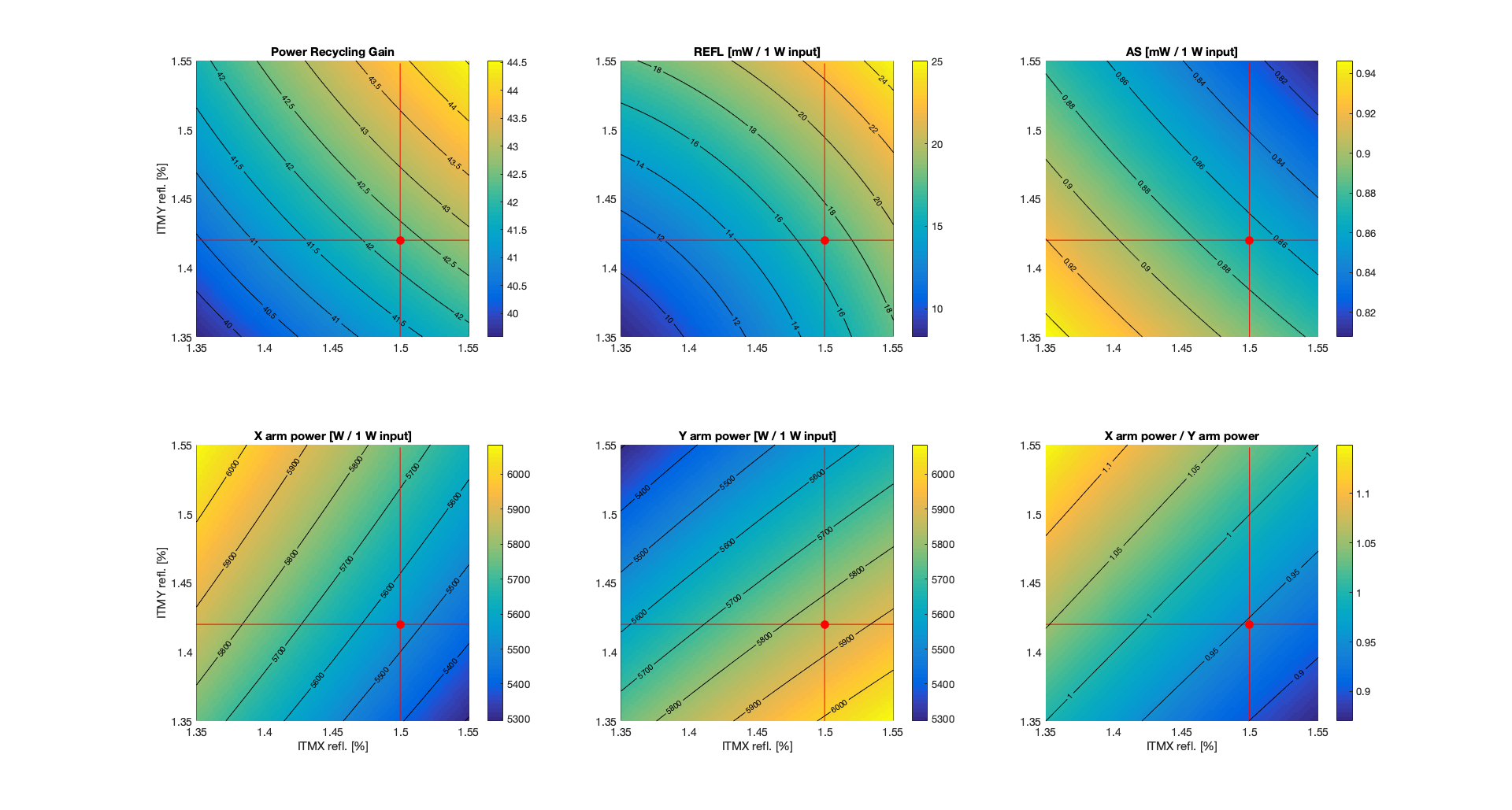
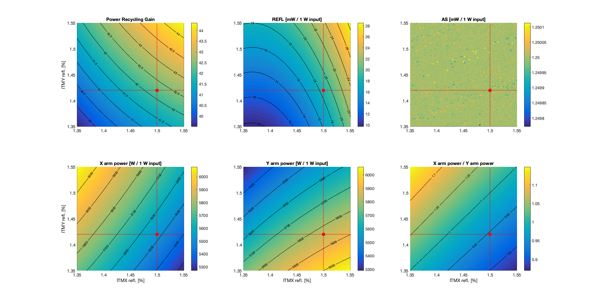
I set up a simple simulation, using only the TEM00 mode, so without including any mismatch. Each arm has about 92 ppm of total round trip losses, following Craig's estimate. The first plot below shows some powers as a function of the two ITM reflectivities. 


The red dot represent the nominal condition, which gives, for 1 W input power

PRG = 42.3
REFL = 17 mW (carrier only, TEM00, perfect matching)
AS = 0.9 mW (carrier only, TEM00m, perfect matching, nominal DARM offset of 1.2e-11 m
XARM = 5536 W
YARM = 5848 W
X/Y = 0.946 [more power in Y arm than X arm]

So there is more power in the Y arm than in the X arm, as one would expect since ITMY has higher reflectivity, so that the Y arm has higher finesse.

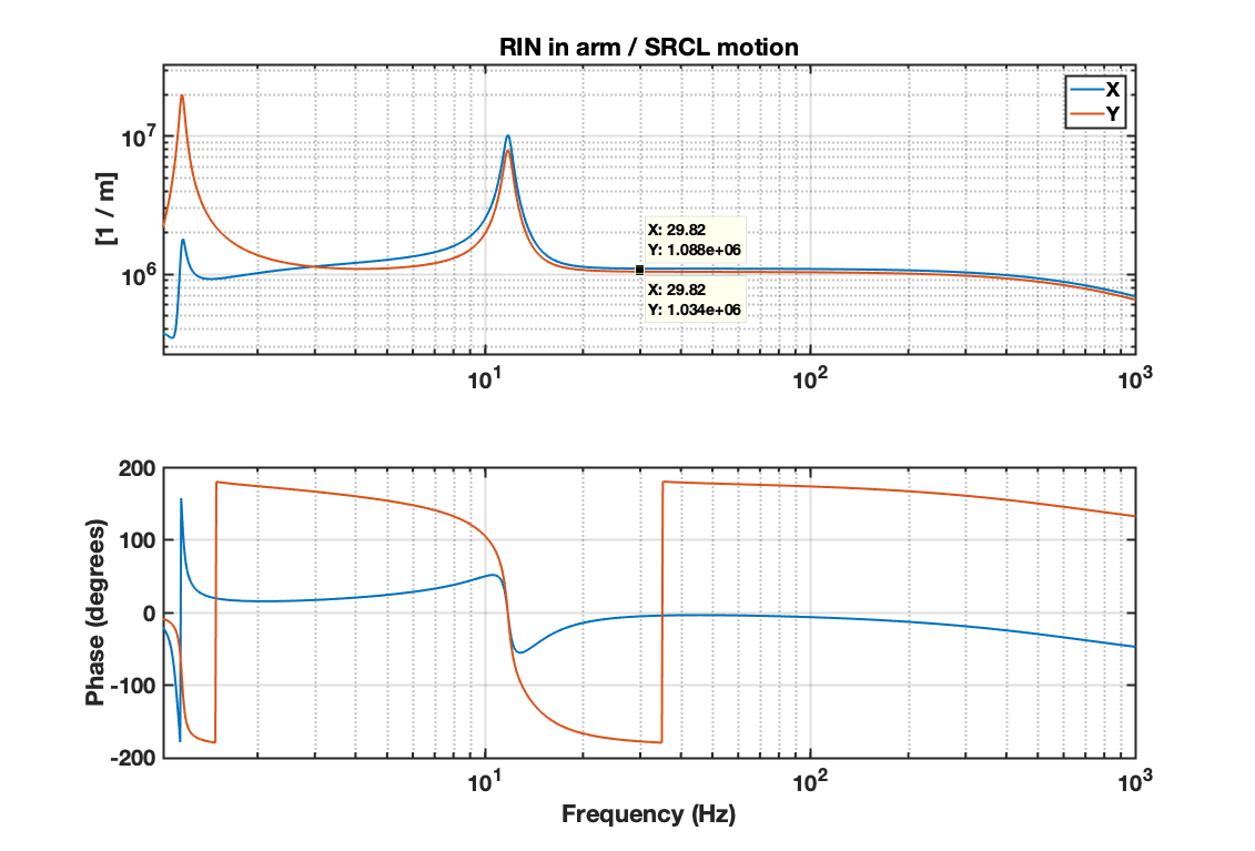
I also tried to reproduce more closely Craig's SRCL dither measurement. So in simulation, I computed the transfer function from SRCL motion to the RIN as measured in transmission of both arms. The plot below shows the simulated transfer functions RIN_ARM / SRCL for X and Y:


The numerical values are

RIN_X / SRCL_z = 1.088e6 /m
RIN_Y / SRCL_z = 1.034e6 /m

so (RIN_X / SRCL_z ) / (RIN_Y / SRCL_z) = 1.052. This is the ratio of powers, since the simulated transfer functions from SRCL to powers are equal for both X and Y, so the transfer functions to RIN are scaled by the inverse of the power. 

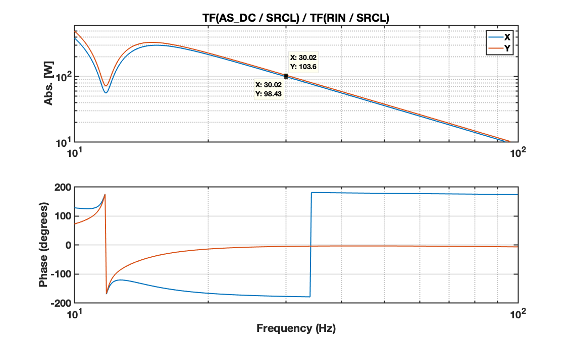
Craig's measurement is actually the transfer function DARM / RIN while injecting on SRCL. In simulation, I used the AS port power as a proxy for DARM and computed the transfer functions TF(AS_DC / SRCL) and TF(RIN / SRCL). Then the equivalent of Craig's DARM / X and DARM / Y should be, at 30 Hz,

TF(AS_DC /  SRCL) / TF(RIN_X / SRCL) = 98.4 W
TF(AS_DC /  SRCL) / TF(RIN_Y / SRCL) = 103.6 W

and the frequency dependency is shown in the plot below (1/f^2 as expected).


So the equivalent of Craig's ratio (DARM / Y) / (DARM / X) should be 

[ TF(AS_DC /  SRCL) / TF(RIN_Y / SRCL) ] / [ TF(AS_DC /  SRCL) / TF(RIN_X / SRCL) ] = 103.6 / 98.4 = 1.053

which is greater than one as in Craig's measurement, but corresponds to the ratio POWER_Y / POWER_X. 

So the conclusion from my simulation is that the ITM different reflectivities gives a ratio of TF (as measured by Craig) greater than 1, which corresponds to higher power in the Y arm than in the X arm (the opposite of what Craig's concluded...)


Images attached to this comment
craig.cahillane@LIGO.ORG - 17:17, Tuesday 29 January 2019 (46698)
I didn't know that the ITMs were not the same reflectivity.  This is absolutely mind-blowing information.
I reported higher arm power in the Y arm before, from the HEPI measurement.  
The RIN/SRCL TF corresponds to Equation 12 here.  It is not dependent on the arm power at all, but rather the optical response γ of each arm to the SRCL dither.
Also, the DARM/RIN TF in Equations 20 and 21 also indicate that DARM/RIN = 4*Parm/(m c ω2), so I made a mistake last night.
gabriele.vajente@LIGO.ORG - 20:41, Tuesday 29 January 2019 (46700)

Good that the measurement and the prediction agree that there is more power in Y than in X.

Now we have to figure out why the measurement gives 8% imbalance while from the ITM reflectivities we only get 5%.

gabriele.vajente@LIGO.ORG - 16:50, Wednesday 30 January 2019 (46710)

Updated simulation: 

  1. added higher order modes (n+m<=10), measured test mass radii of curvature
  2. locked DARM to have an AS power that corresponds to 20 mA at 26 W input power (1.25 mW on the OMC transmission for 1 W input)

No change in the conclusions. Same imbalance of the arm powers as before (about 5%) 


Images attached to this comment
gabriele.vajente@LIGO.ORG - 09:43, Thursday 31 January 2019 (46720)

Adding the substrate lenses do not change significantly the power imbalance. 

ITMX: static lens -310km, thermal lens +770km
ITMY: static lens +570kn, thermal lens +350km

gabriele.vajente@LIGO.ORG - 14:46, Friday 01 February 2019 (46749)

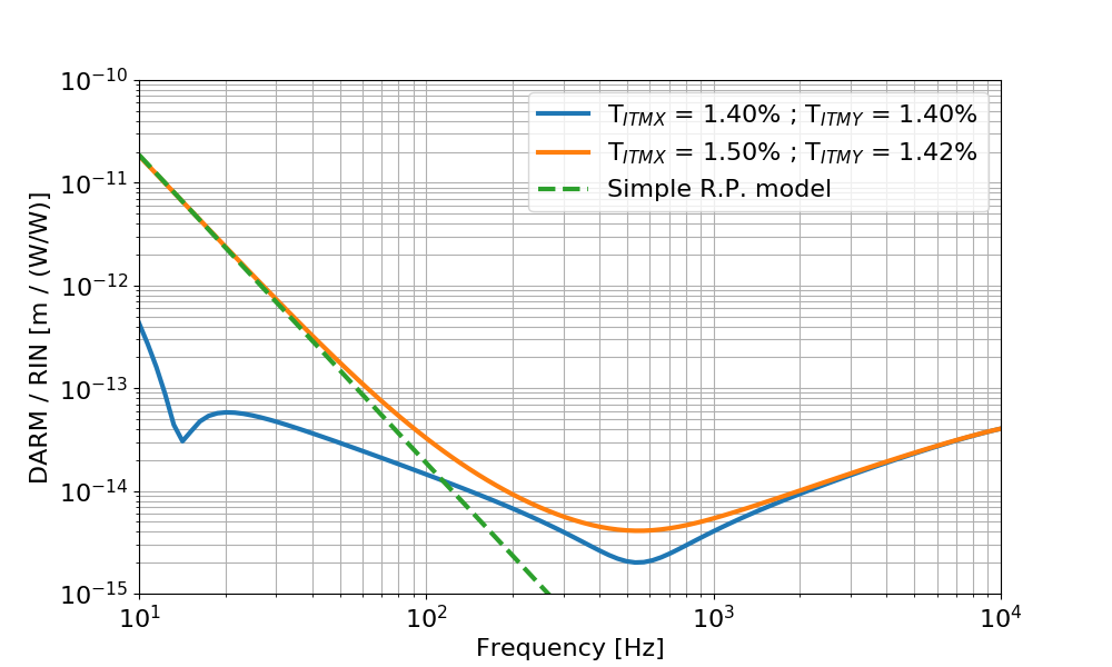
Follow up to the discussion at today's commissioning call.

I computed the transfer function from laser relative intensity noise at the IFO input (called rin below) to DARM (calibrated in meters). 

The input power is 26 W, and the round trip losses are adjusted to get a recycling gain of about 42. In the blue trace below, the two ITMs have the same reflectivity, equal to the nominal value of 1.4%. In the orange trace the two ITMs have different reflectivities, ITMX = 1.50% and ITMY = 1.42%, from the measured values from galaxy. This is the same configuration used in the other simulations, that gives a 5% power imbalance. 

The dashed green curve is a simple radiation pressure model according to the equation below:


where RIN_arm / RIN_input is basically the double cavity pole (since input RIN is filtered by this transfer function. I used the simulated result), Delta P is the DC power difference in the arms ( Y - X = 7.7 kW) and m is the mirror mass. This matches quite well the low frequency simulation.


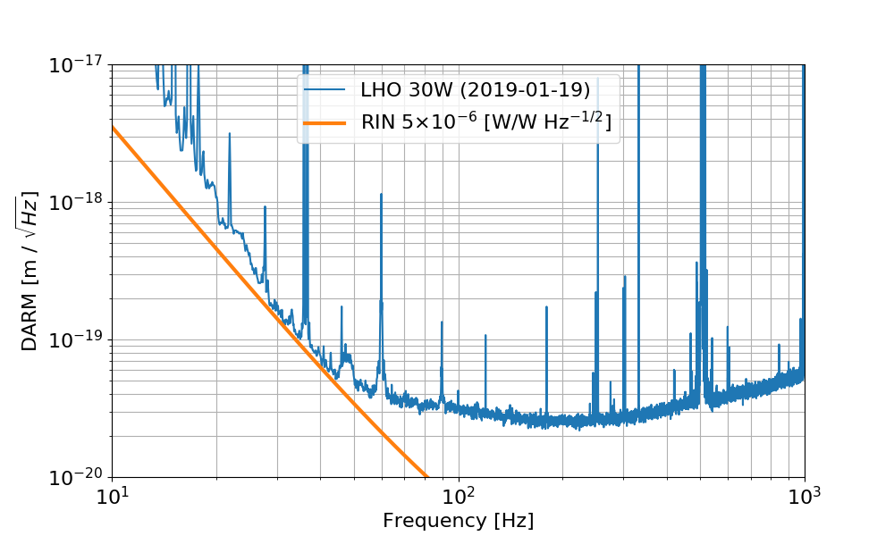
Using the simulated transfer function I can see what level of RIN at the IFO input would limit the sensitivity. It turns out that one needs a RIN of about 5e-6 (W/W)/rHz. 


Images attached to this comment
gabriele.vajente@LIGO.ORG - 11:18, Monday 04 February 2019 (46759)

I found a mistake in my previous RIN simulation (many thanks to Matt Evans for spotting the inconsistency). Here's the correct results and plots.

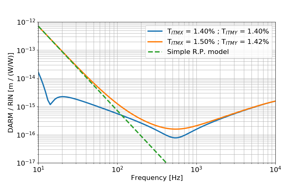
Follow up to the discussion at today's commissioning call.

I computed the transfer function from laser relative intensity noise at the IFO input (called rin below) to DARM (calibrated in meters). 

The input power is 26 W, and the round trip losses are adjusted to get a recycling gain of about 42. In the blue trace below, the two ITMs have the same reflectivity, equal to the nominal value of 1.4%. In the orange trace the two ITMs have different reflectivities, ITMX = 1.50% and ITMY = 1.42%, from the measured values from galaxy. This is the same configuration used in the other simulations, that gives a 5% power imbalance. 

The dashed green curve is a simple radiation pressure model according to the equation below:


where RIN_arm / RIN_input is basically the double cavity pole 0.6Hz/fr (since input RIN is filtered by this transfer function), Delta P is the DC power difference in the arms ( Y - X = 7.7 kW) and m is the mirror mass. This matches quite well the low frequency simulation.

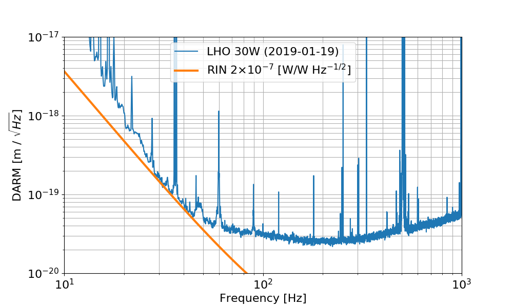
Using the simulated transfer function I can see what level of RIN at the IFO input would limit the sensitivity. It turns out that one needs a RIN of about 2e-7 (W/W)/rHz


Images attached to this comment
matthew.evans@LIGO.ORG - 15:35, Monday 04 February 2019 (46772)

Doesn't this 2e-7 /rtHz RIN seem dangerously close to the measured value at 30Hz?

sheila.dwyer@LIGO.ORG - 20:49, Monday 04 February 2019 (46780)

The intensity noise projection in the noise budget is made by injecting into the ISS second loop.  It shows that the intensity noise is not close to DARM.  45828


LHO VE
kyle.ryan@LIGO.ORG - posted 16:56, Tuesday 29 January 2019 (46697)
CP3's high level due to delivery and software minimum?

CP3 had a delivery today and is now running a little "full" as a result.  The LLCV output won't go below 13%.  I think that this value was programed as a software minimum to prevent the transfer line from warming up back when we were sorting things out, either during the sensing line blockage era or during the conversion from pneumatic to electric control valve.  Regardless, it is a non-issue. 

H1 General
jim.warner@LIGO.ORG - posted 15:59, Tuesday 29 January 2019 (46687)
Shift Summary

16:00 Rick, Nico to EY to work on PCAL

17:00 TVo, TJ, Danny to LVEA

17:45 Travis to LVEA

18:00 Fil to ISCT6

18:00 Jeff, Evan to EX

19:00 Marie to LVEA

19:00 Bubba and contractors to LVEA

19:45 Jeff Evan back to EX

21:00 Richard and Patrick to EX


H1 CDS
jonathan.hanks@LIGO.ORG - posted 15:32, Tuesday 29 January 2019 (46696)
Quality of life improvement, channel name completion is available for some common commands
At the suggestion of Koji we put the bits together to bring command line channel completion to a few common commands.  So for the following commands a tab will help find the next stop in the channel name.

 * ndscope
 * probe
 * caget
 * caput
 * camonitor
 * cdsutils

$ caget H1:PEM- tab tab
PEM-CS     PEM-EX     PEM-EY     PEM-MX     PEM-MY     PEM-ODC    PEM-PCIE   PEM-PEM    PEM-VAULT  PEM-X      PEM-Y
H1 CAL (CAL)
richard.savage@LIGO.ORG - posted 15:29, Tuesday 29 January 2019 (46695)
Pcal Yend responsivity ratio measurements and installation of beam path apertures

NikoL, DimitriEstevez (Virgo), RickS

This morning, we repeated the end station calibration measurement procedure (T1500062-v7).  The calibration log is attached below.

The values measured today are within 0.1% for both sensors.

Sensor Dec. 13 Jan. 15 Jan. 29  ratio (Jan 29/Jan 15)
Tx (V/V) -0.480810 -0.480448 -0.480937 1.00093
Rx (V/V) -0.715832 -0.715410 -0.716157 1.00104

The beam positions at the Rx power sensor aperture are a bit high and to the right (see attached photo).

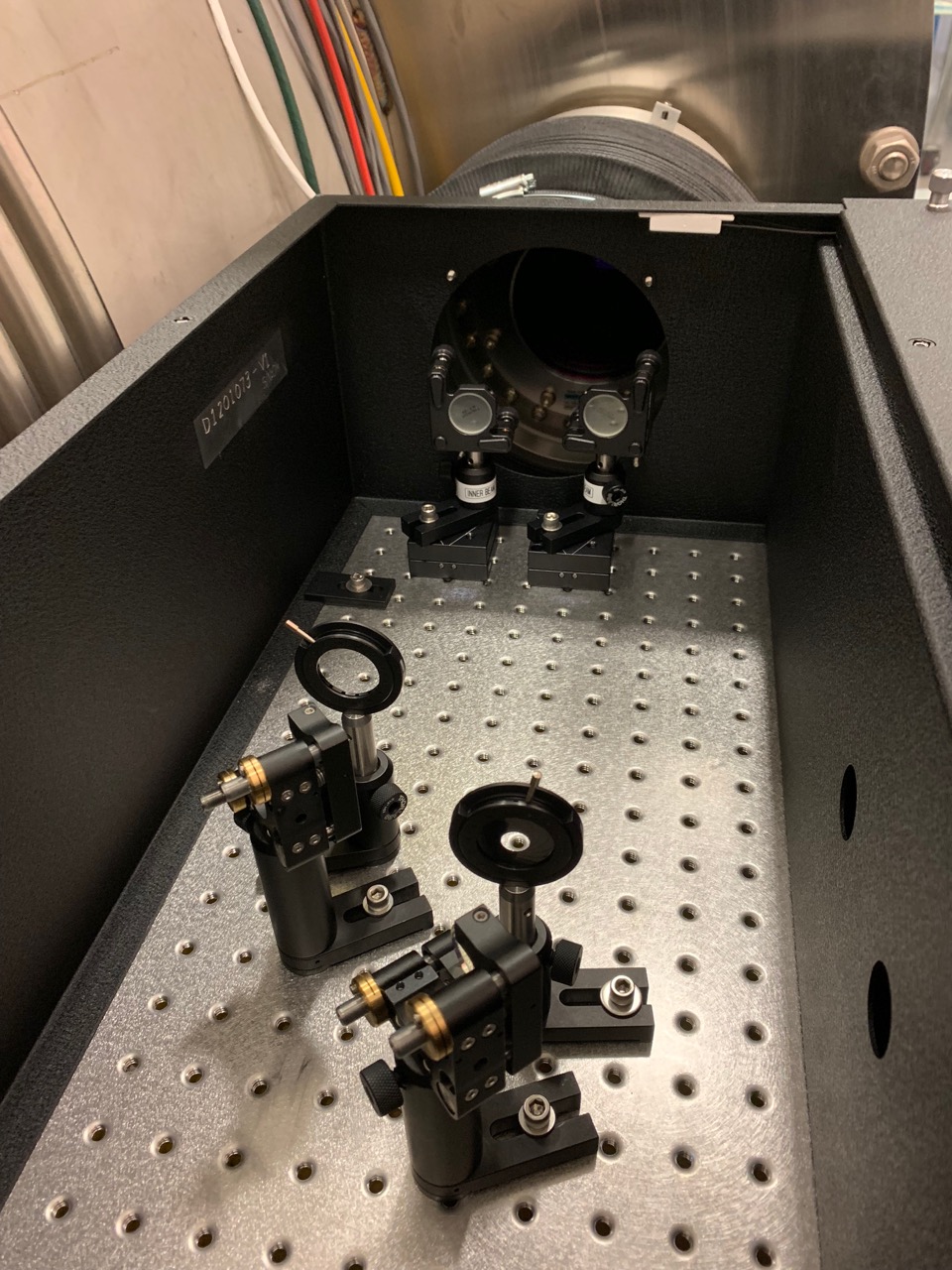
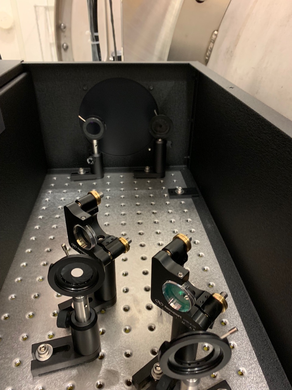
We also installed the beam path irises and relay mirror mounts on kinematic bases to help find the beam paths in case of catastrophic laser failure (see attached photos).

The shutter, recently repaired by FilibertoC and RichardM, has not yet been re-installed.

Images attached to this report
Non-image files attached to this report
H1 General (CAL, DAQ, DetChar)
john.zweizig@LIGO.ORG - posted 13:51, Tuesday 29 January 2019 (46693)
LHO dmt software upgraded, restarted
I have updated the dmt software to gds-2.18.13 with ldas-tools-framecpp-2.6.5 and restarted all the dmt processes on h1dmt0, h1dmt1 and h1dmt2. There seems to be an obsolete dependence somewhere in the build for the streaming omega pipeline executable that I have no idea where it is coming from. Everything else seems to be running correctly and I expect that I will be able to fix up omega by hand when I figure out what is going on. 
H1 AOS (AWC, TCS)
thomas.vo@LIGO.ORG - posted 13:17, Tuesday 29 January 2019 (46692)
SRM CO2 Alignment, Pitch Good, Yaw clipping

TJ, Marie, Danny, TVo

During the maintenance period, we tried to fine tune the alignment of the CO2 laser by using the single bounce interferometer beam on SRM and look at the deflection at the AS port sensors (AS_A_DC and AS_B_DC) to overlap the CO2 with the IFO beam.  Our rough alignment was simply getting the beam centered on the viewport and centered on the first mirror in chamber, and hope that this is close enough to only adjust the top periscope mirror.

First, we had an issue with getting the suspensions to locally damp so there wasn't any light at the AS port, Jim and Corey tracked this down to a computer error in H1IOPSUSB123.

After that, we tried to align the SRM CO2 alignment into the chamber and found that we were able to get pitch relatively easily with the top periscope mirror but yaw was much more painful because as soon as we started to get close to overlapping the interferometer beam, it would start clipping either on the first mirror or the input hole of the SRM AR baffle.  For reference, I've attached a drawing from Corey A. showing the nominal beam path.  We then tried walking the beam with the top and bottom periscope mirrors but it wasn't helpful.  The next step may be to move the table and walk the beam with the top periscope mirror but we ran out of time.

Non-image files attached to this report
LHO FMCS
bubba.gateley@LIGO.ORG - posted 13:06, Tuesday 29 January 2019 (46691)
Decouple Work Platform from BSC 10
We decoupled the work platform from BSC10. 
Reference W.P. 8066. 
LHO FMCS
bubba.gateley@LIGO.ORG - posted 13:02, Tuesday 29 January 2019 (46689)
Fiber Optics Cable Re-Covered
The exposed fiber optic on Y-Arm was re-covered this morning. 
This is referenced in W.P. 8064. 
H1 CDS
patrick.thomas@LIGO.ORG - posted 10:58, Tuesday 29 January 2019 - last comment - 13:00, Tuesday 29 January 2019(46686)
Updated h1ecatx1 to add binary readout of ISCTEX enclosure fan status and control of ISCTEX enclosure light
Patrick, Filiberto

I created a TwinCAT library named Enclosure for the control of table enclosure lights and the readout of table enclosure fans. I added the necessary code to PLC1 for the end stations to handle the fans and lights on ISCTEX and ISCTEY.

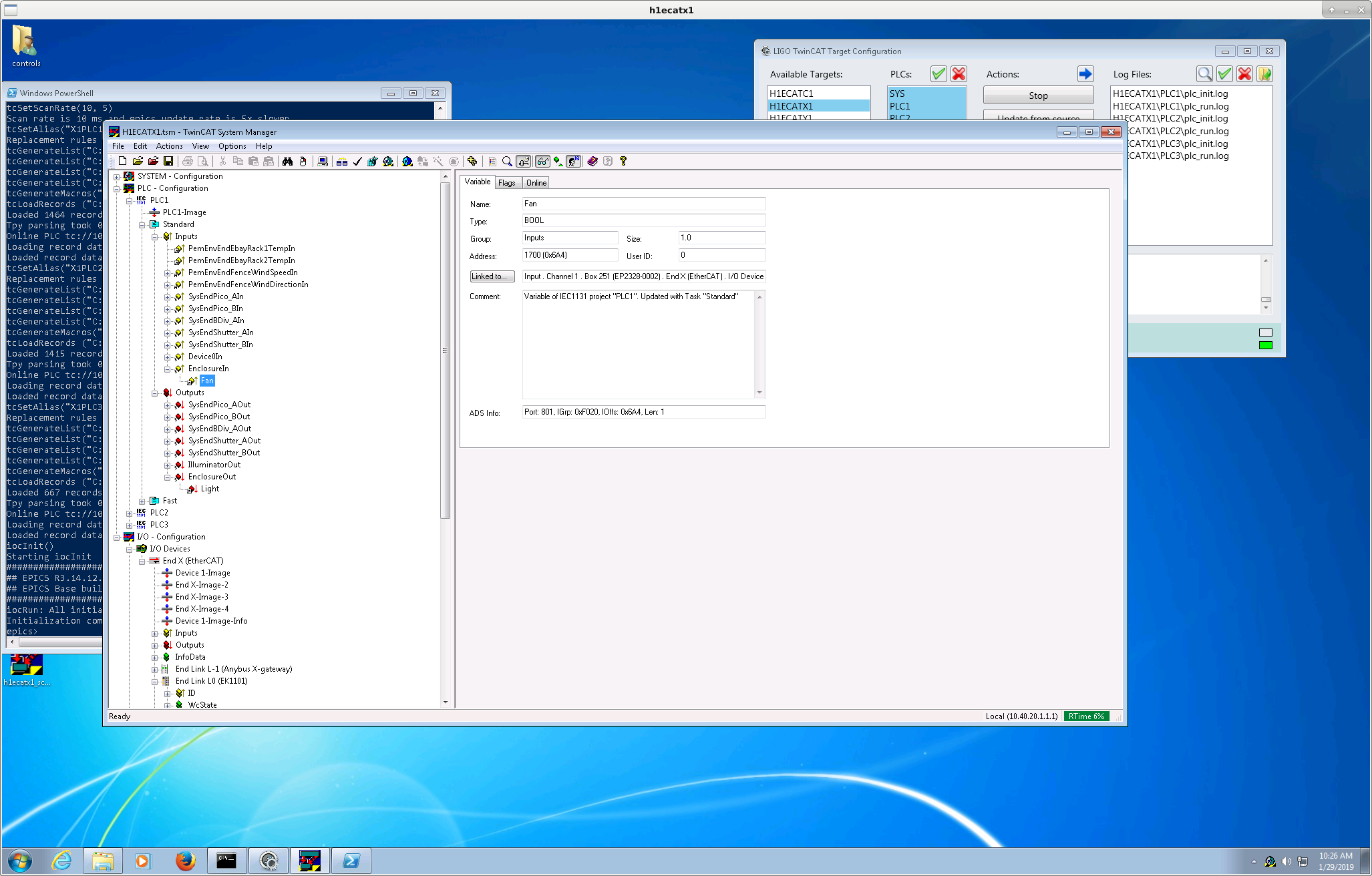
Today Filiberto added a EP2328-0002 EtherCAT box after the ALS Laser Table Relay (EP2624-0002) at end X (Box 251 in the first screenshot). I updated the h1ecatx1 system manager to add this box. I linked the readout of the fans to channel 1 of this box, and the control of the lights to channel 3 of the ALS Laser Table Relay box.

I have not run svn update for end Y.

The channel names are:
H1:SYS-ENCLOSURE_X_ISCTEX_LIGHT
H1:SYS-ENCLOSURE_X_ISCTEX_FAN

These are set to be in alarm at a value of True.

Filiberto stated that the fans and lights are not yet connected to this box, so these channels are not currently valid.

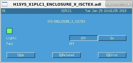
The autogenerated medm screen can be accessed from SITEMAP -> SYS -> EtherCAT overview -> H1 X1 PLC1 -> Sys -> Enclosure -> X -> Isctex
Images attached to this report
Comments related to this report
filiberto.clara@LIGO.ORG - 13:00, Tuesday 29 January 2019 (46690)

Modified chassis installed is S1400568. Cabling from chassis to table enclosure still need to be pulled, likely next Tuesday.

1. 24V for table enclosure lights
2. 15V TCS
3. Fan Status

Displaying reports 43301-43320 of 88618.Go to page Start 2162 2163 2164 2165 2166 2167 2168 2169 2170 End