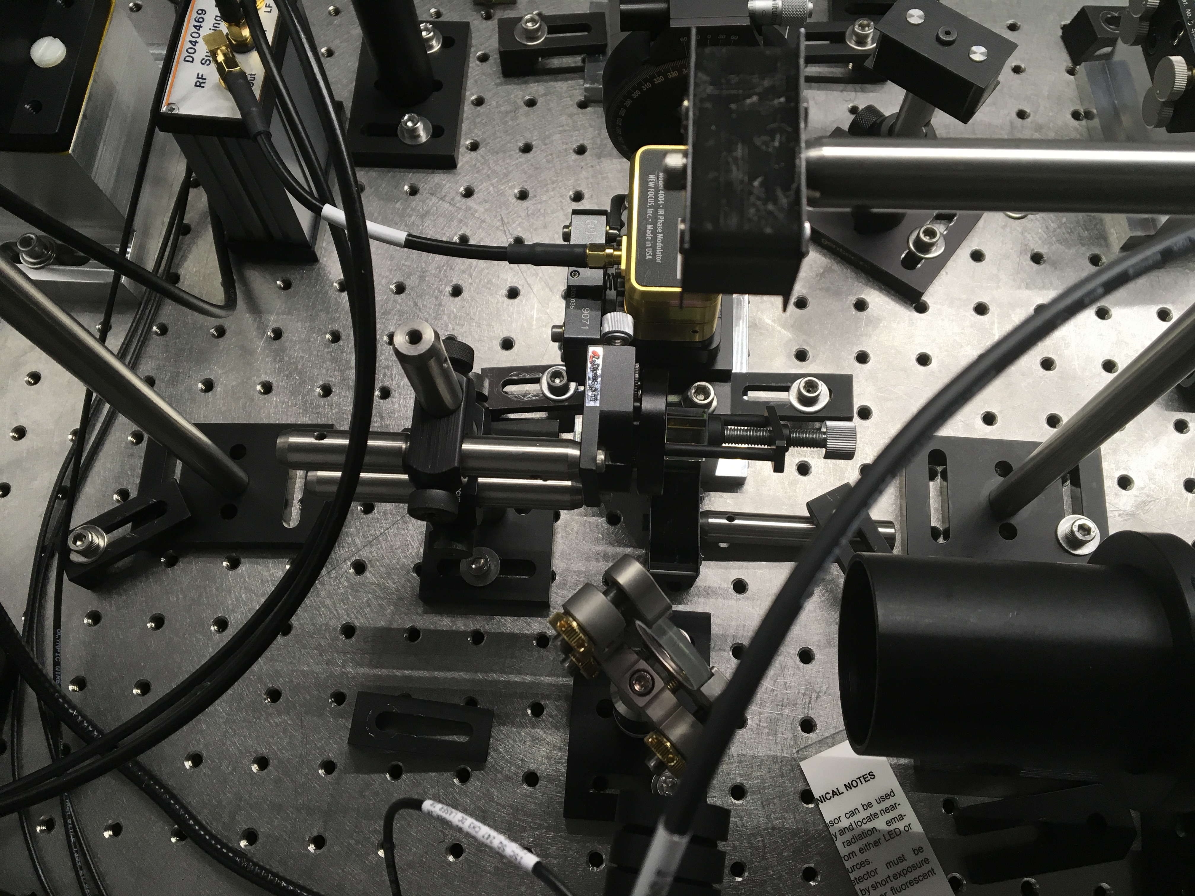
The mount for the PZT in the IO path on the PSL, IO_MB_M4, was swapped from the 2" mirror and the damped mount to the new PZT mount.
Aligning with the new PZT mount is challenged by having to remove the entire mount from the table, to access the bolts underneath, to adjust the +/-X position. There was also a change of the beam alignment when securing the bottm plate to the table. The beam was carefully aligned to IO GigE camera 2 and camera 3, and when the bottom plate of the new mount was secured to the table, the beam was gone from both cameras, and an offset was introduced into the IMC_IN beam. With the PZT it was possible to restore a beam to IO GigE 2, the camera that is on the bottom periscope transmitted beam. It was not possible to restore both camera images with the PZT. This indicates that the change in IMC_IN position and angle are due to the PZT swap. It was past noon, so the decision was to leave this change as is, lock the IMC, and evaluate how it and the beam downstream was affected, instead of using M3 and the PZT on the PSL, to restore an image to both cameras. The change in IMC_IN on the iris at the bottom periscope was identifiable as yaw with an IR viewer.
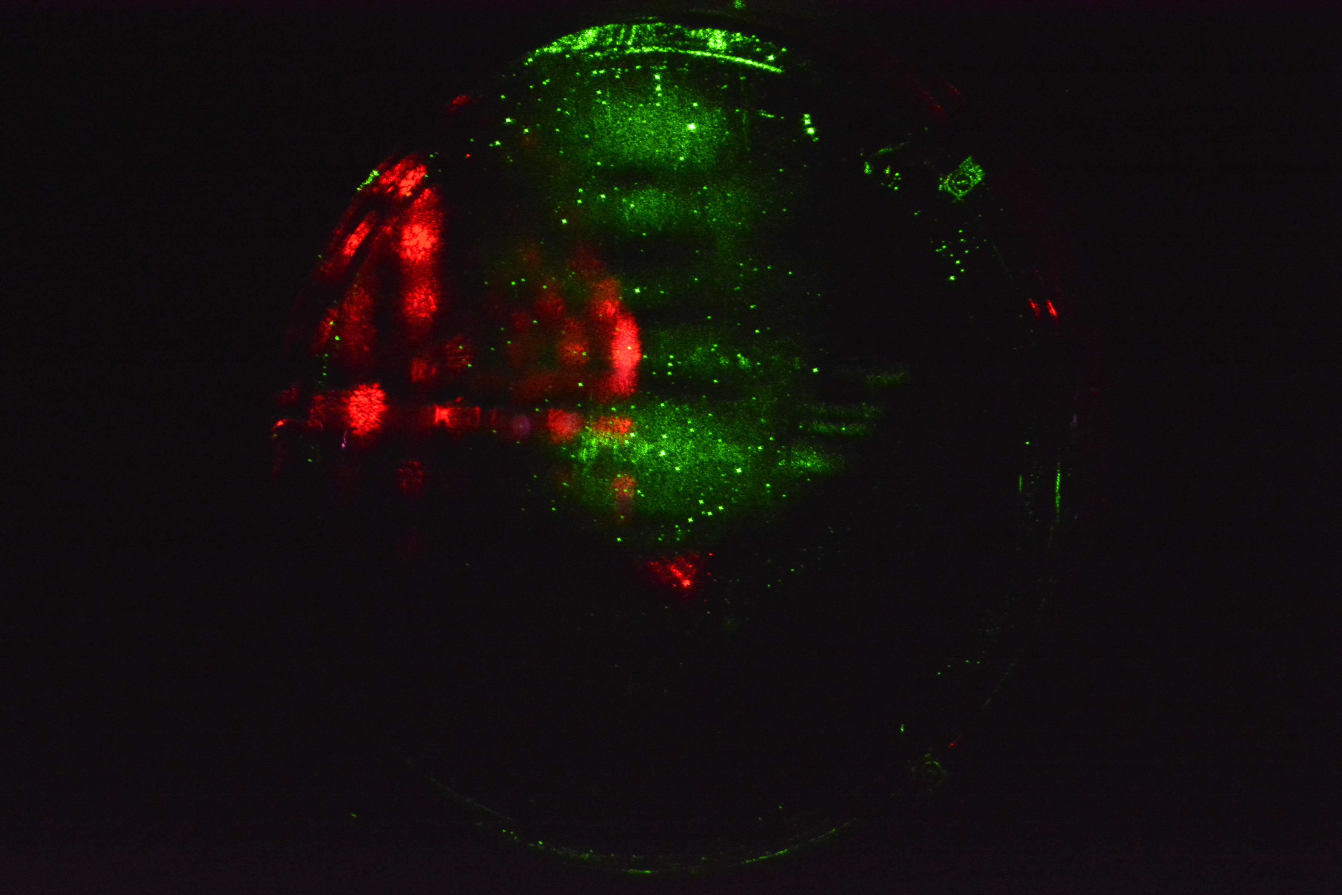
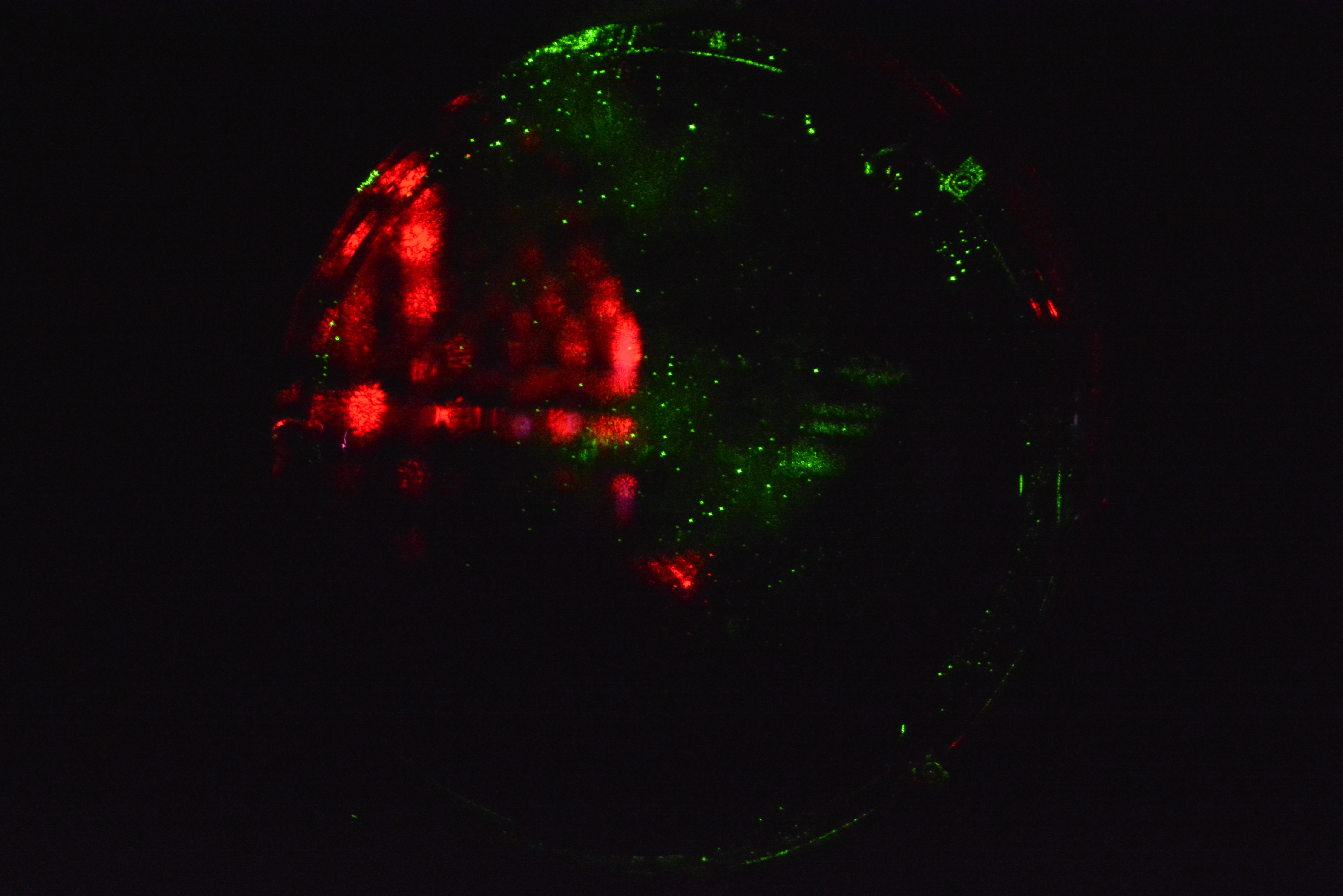
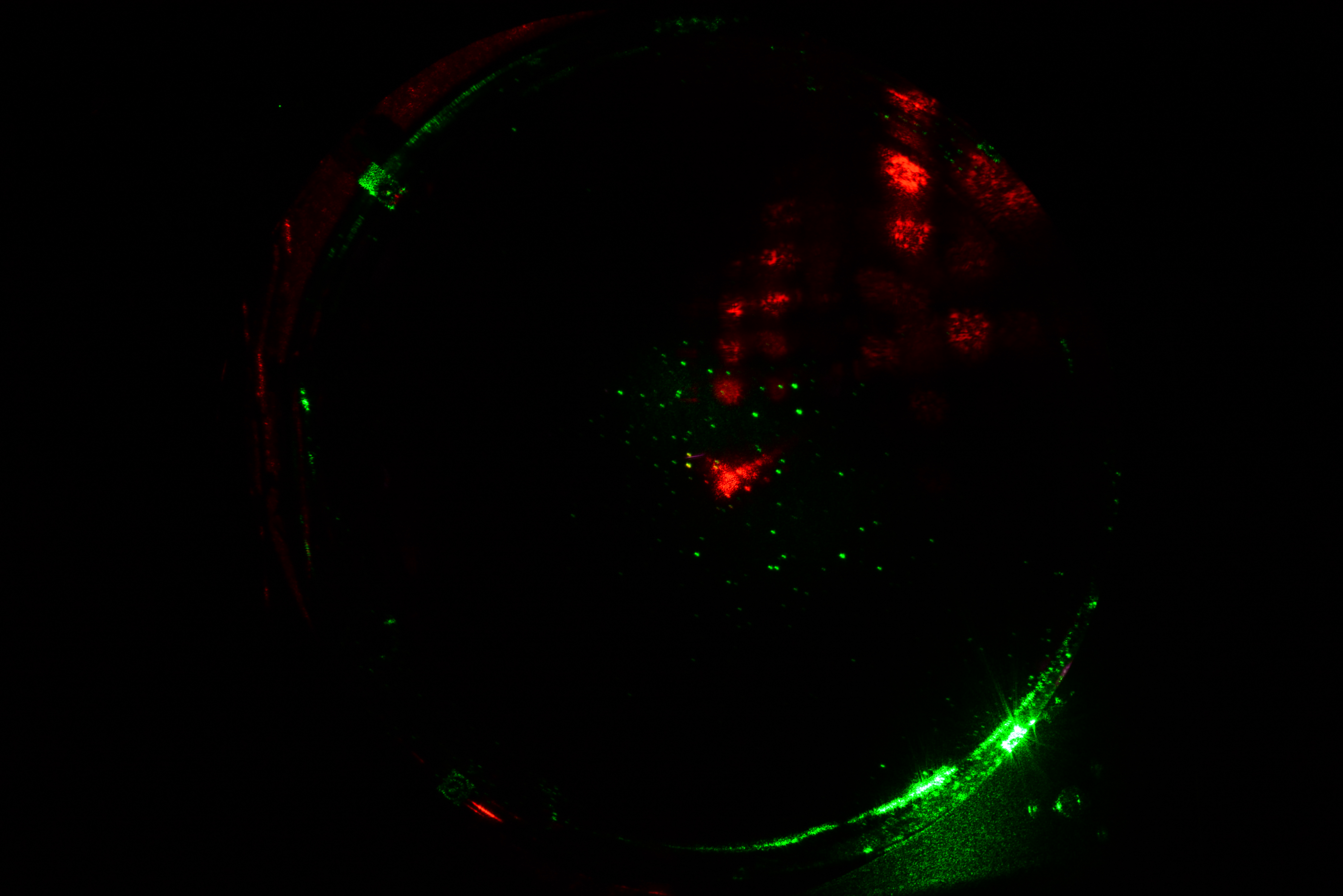
The reference beam from the shutter (between the PSL and HAM1) was recorded before and after the PZT swap. Those pictures show the difference is between the before and after beams is 1mm and 2mm in pitch and yaw (image attached).
Sheila and JeffK moved IMC DOF, Corey and JeffK started an initial alignment, and now the effort is to lock.
BEFORE reference time 12/11 18:00 UTC, AFTER reference time 12/12 1:24 UTC. A snapshot showing IMC WFS, IM4 Trans, and ISS Second Loop QPD signals is attached.
- Cheryl, Jason, Keita

Two drawings. The first shows the layout of the IO GigE cameras 2 and 3, both on the bottom periscope transmitted beam (IMC_IN). The second shows the change (exaggerated for clarity) of the front face of the PZT mirror (placed on the table vs secured).

This mount swap is in reference to IIET Ticket 5132.
The new mount is documented by the below details:
- ICS Record (thanks JeffB!): ASSY-D1700002-2
- Drawing: D1700002