Following on alog 45653 and FRS 11921/10987 went down to EX to troubleshoot.
1. Power cycled PCAL chassis, temperature readbacks still glitchy.
2. Disconnected both the Transmitter and Receiver temperature sensors. Readbacks showing 0 counts.
3. Two spare AD590 sensors connected. Readbacks signals still glitchy.
4. Unit was brought back to EE lab. Output of chassis for temperature sensors both stable.
5. Unit was returned to End X.
6. Used 2 voltage calibrators and injected to Beckhoff, both readback signals stable.
7. Reinstalled cabling and power back up. Accidently connected shutter to temperature readback port causing the +15V to dim on front panel.
8. Power down and corrected cabling, power back on, tested shutter locally.
9. Both temperature sensors showing valid temperatures.
F. Clara, P. King
This morning I swapped a couple of OpLev Lasers around the site. I took the less glitchy lasers from SR3 and PR3 and replaced the end station lasers that have been very glitchy and vice-versa. All centering remained nominally intact. There was a gain adjustment necessary for SR3. The gain setting was +3dB and it was changed to 0dB. This brought the sum count from ~40K to ~28K. After temperature stabilization, spectrograms will be checked, and if needed, power adjustments will be made to quiet down any "new" glitching.
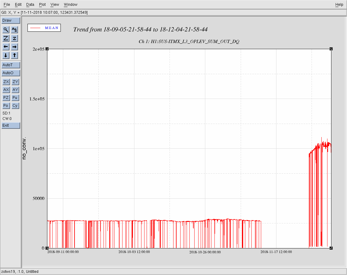
Unrelated to this swap, ITMX OpLev, is showing an increase in sum by a factor of 4 (post vent). This remains a mystery until I can go and try effecting a change by a direct power adjustment and/or checking/correcting gain settings at the whitening chassis. Nothing was directly done with this unit directly prior to or after the vent. It is very unusual.
J. Oberling, R. Schofield
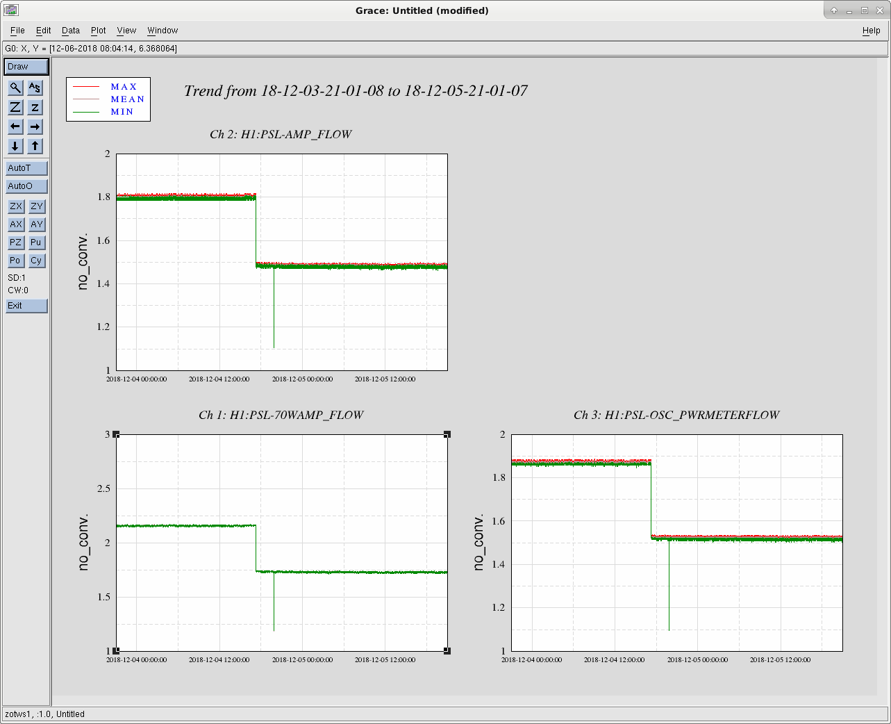
At Robert's request I lowered the flow rates of the PSL cooling circuits by ever so slightly opening the bypass valve in the chiller room. Our target was to get the flows close to 1.5 lpm. In the past, the flow meters were happy with flows at this level (unlike when we were running with a flow closer to 1.0 lpm and the meters became very glitchy). Robert will assess how this small change effects PSL table motion; I will keep an eye on the flow meter readings to see if they become glitchy again.
Flow rates before change:
Flow rates after change:
Attached are the relevant flow rates for the last 2 days; the change in flow is clearly seen. What looks like a single glitch shortly after the change is actually not. While we were in the PSL enclosure Robert requested that we slightly open the bypass valve on the manifold (the valve on the old HPO crystal cooling circuit) for a few seconds to release any trapped air bubbles. This is the cause of the apparent flow glitch, not an actual glitch in the reading from the flow meters. Therefore, after >24 hours there have been no glitches in the flow rate. I will continue to monitor this, but so far everything looks stable.
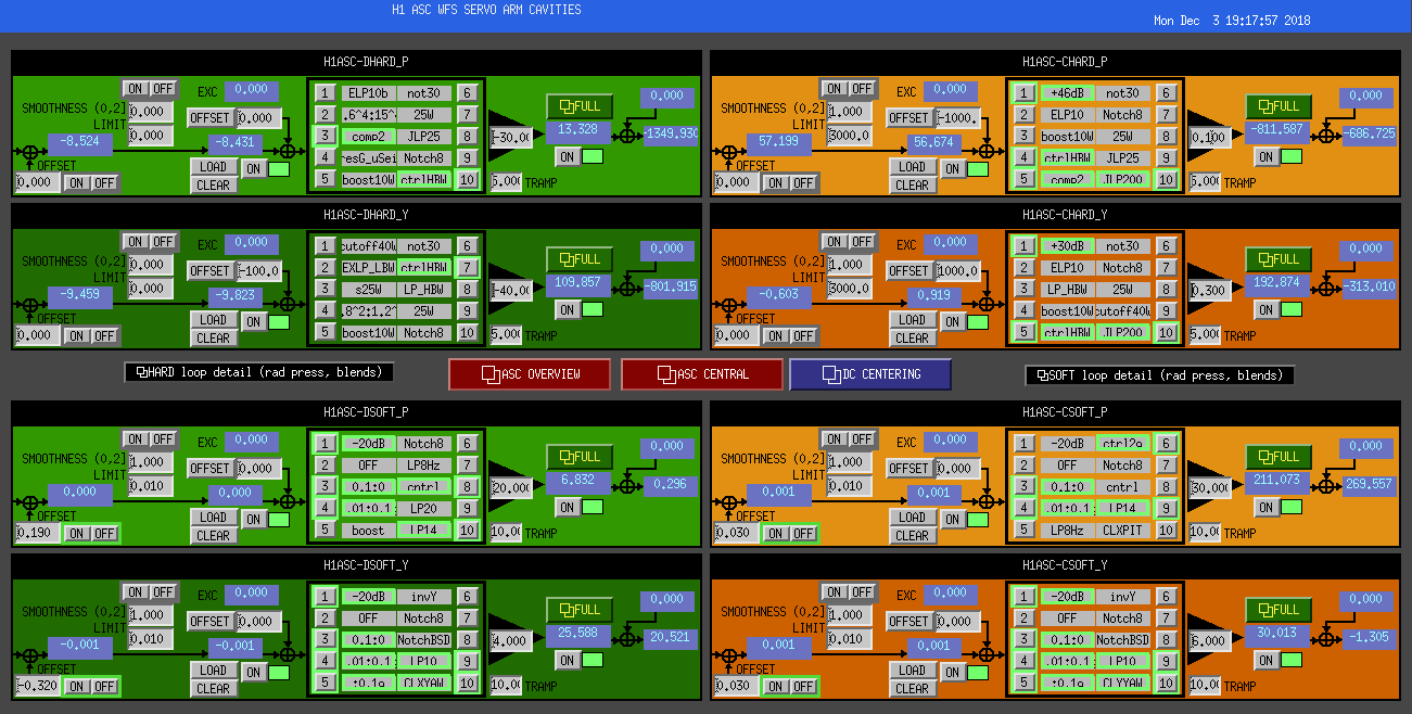
The smooth limiter at the input of all of our ASC loops now ramps the input offset, and also ramps the limiter. So, if you need to change the limit while the limiter is on, it'll ramp - this is an all new feature for gravitational wave interferometry!
WP7929 ISI BSC Senscor Fader
Jim W, T. J., Dave:
New models for h1isi[etmx, etmy, itmx, itmy, bs] and h1seiproc were installed. DAQ restart was needed.
WP7972 mode cleaner M3 lock-loss trigger
Patrick, Dave:
new h1susmc[1,3] models were installed. DAQ restart was needed.
WP7979 ASC smooth limiter ramp
Jenne, Dave:
New h1asc model was installed. DAQ restart was needed
WP7976 h1oaf1 Dolphin Card Relocation
Dave:
h1oaf1 was powered down to relocate its IXH611 Dolphin PCIe card from slot2 to slot3 for consistency with all other front ends. Jeff updated h1calcs's SDF before the shutdown.
DAQ Restarts:
Dave:
DAQ was restarted twice:
08:44 PST for h1susmc[1,3] and h1isi[etmx, etmy, itmx, itmy, bs] model changes
11:21 PST for h1seiproc and h1asc model changes.
No Beckhoff changes this week.
WP7978 GDS low latency frame size modification
Greg, TEAM-GDS:
The production GDS software is being changed to reduce the size of the HofT low latency frame from 4S to 1S.
I will forever more pronounce this the Senscor Vader. Much cooler.
Two more h1asc restarts for minor fixes.
Found a binary issue with h1isiitmx. Initially we power cycled CPU + IO-Chassis + binary-IO-chassis (no change), then found a model issue so installed new model. Still working this problem.
Dan B. , Danny V.
Can you add the product number of the bandpass filter than you've added?
Hey Aidan,
Bandpass product number: FB800-40
1064nm notch filter product number: NF1064-44
- To power to 30W, we turned off the 'BOOSTS' (FM5 in DHARD P&Y and FM3 in CHARD P, labeled 'boost10W').
- Turned ISS 2nd loop off and back on with AC coupling (ISS_ON).
- Stepped up to 30W nominal lownoise configuration.
- Stepped up the RP compensation gains to 1.6 at 30W (same sign as ASC control)
- We lost it on a simple SRC ASC yaw runaway (most likely SRC1 Y).
- We got a good range reading (with good calibration lines) at 25W - 85Mpc.
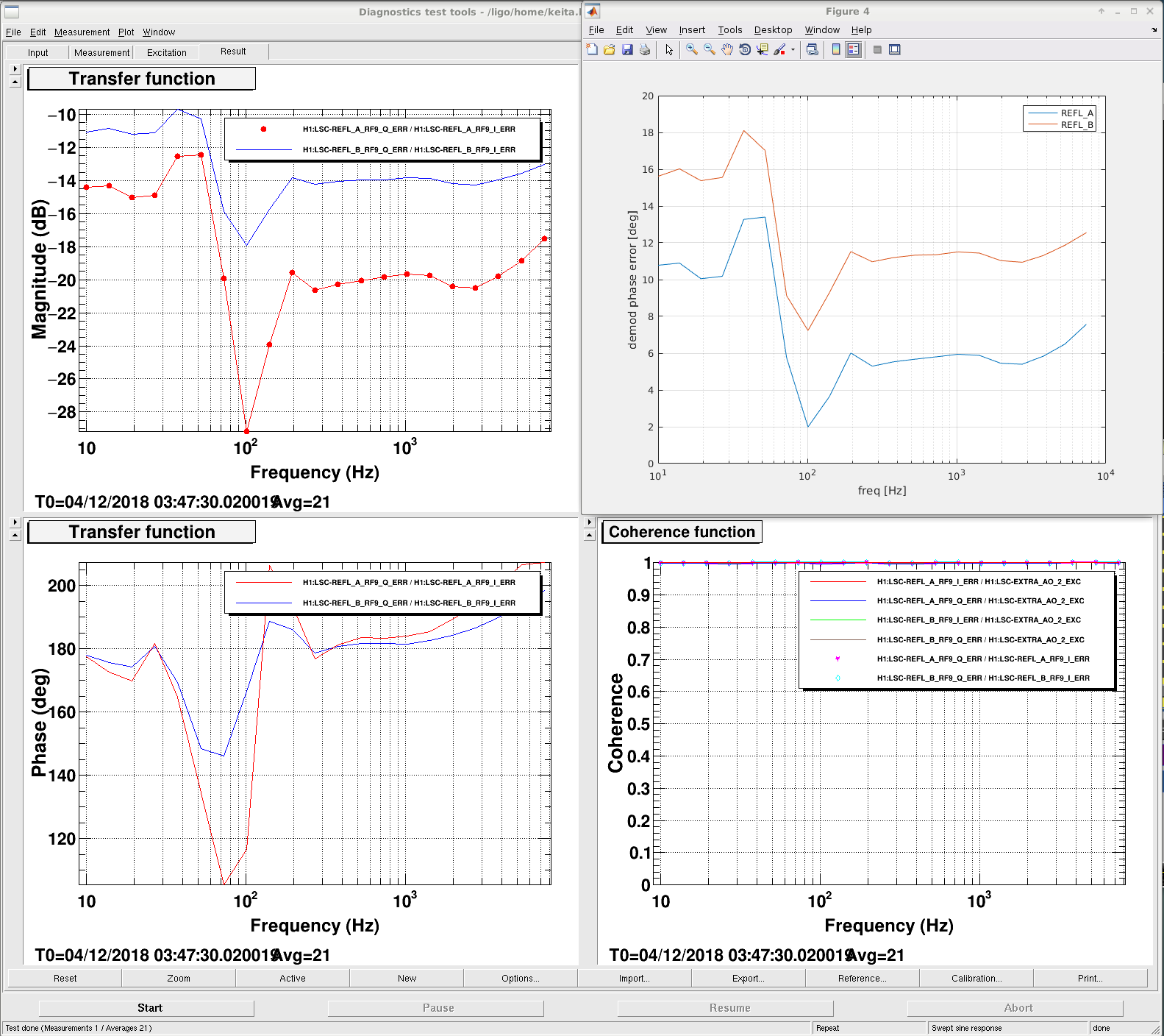
After Fil and I swapped the REFL_B cable (alog 45652) I connected LSC-EXTRA_AO_2_EXC to IFO REFL CM board EXC and injected frequency noise in ENGAGE_DC_VIOLIN (2W) to see the demod phase of REFL_B and REFL_A.
First attachment shows the Q/I ratio obtained from the frequency noise scan. Top right shows the demod phase "error" obtained by p=atan(Q/I). Apparently REFL_A demod phase is decent, REFL_B is not terrible but could be improved.
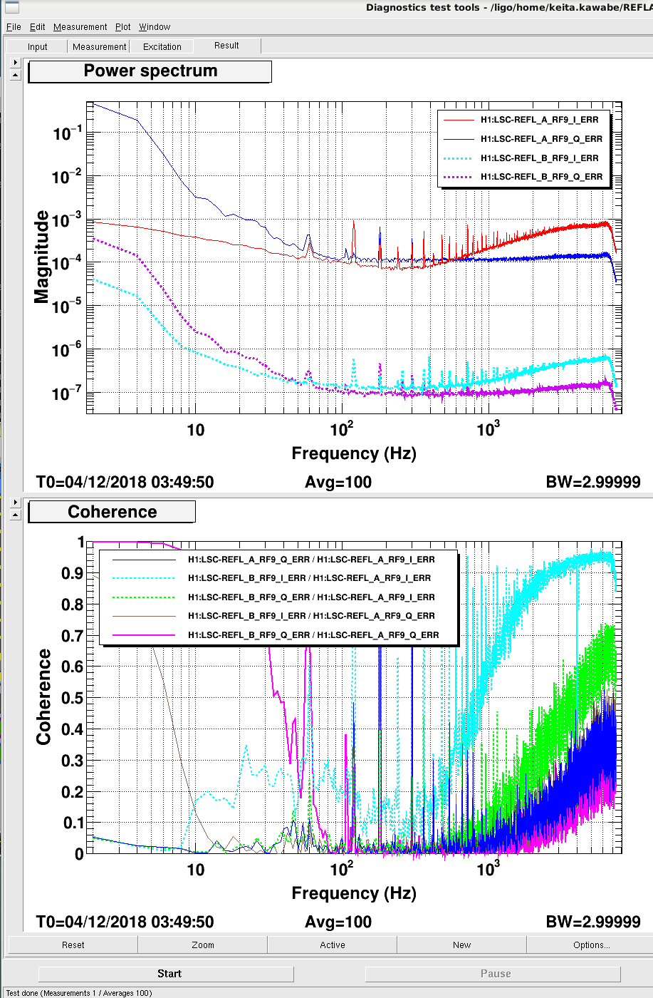
Demod phase error should be flat but it isn't, it seems to cross zero at around 100Hz for REFL_A (maybe the demod phase was set using 100Hz excitation?). HOM or something else, regardless of the cause, this seems to mean that if we optimize the demod phase at f>300Hz there's some I-Q mixing in f<80Hz or so, and vice versa. Since I don't see any real Q signal for f>300Hz but there seems to be some junk for f<100Hz (second attachment), we might be better off optimizing at low frequency.
Not too much low frequency coherence between REFL_A and B, it's not clear if this comes from demod phase difference. Since we're not using REFL_B for control, from this point on we could rotate B phase digitally.
It's also worth measuring this at high power.
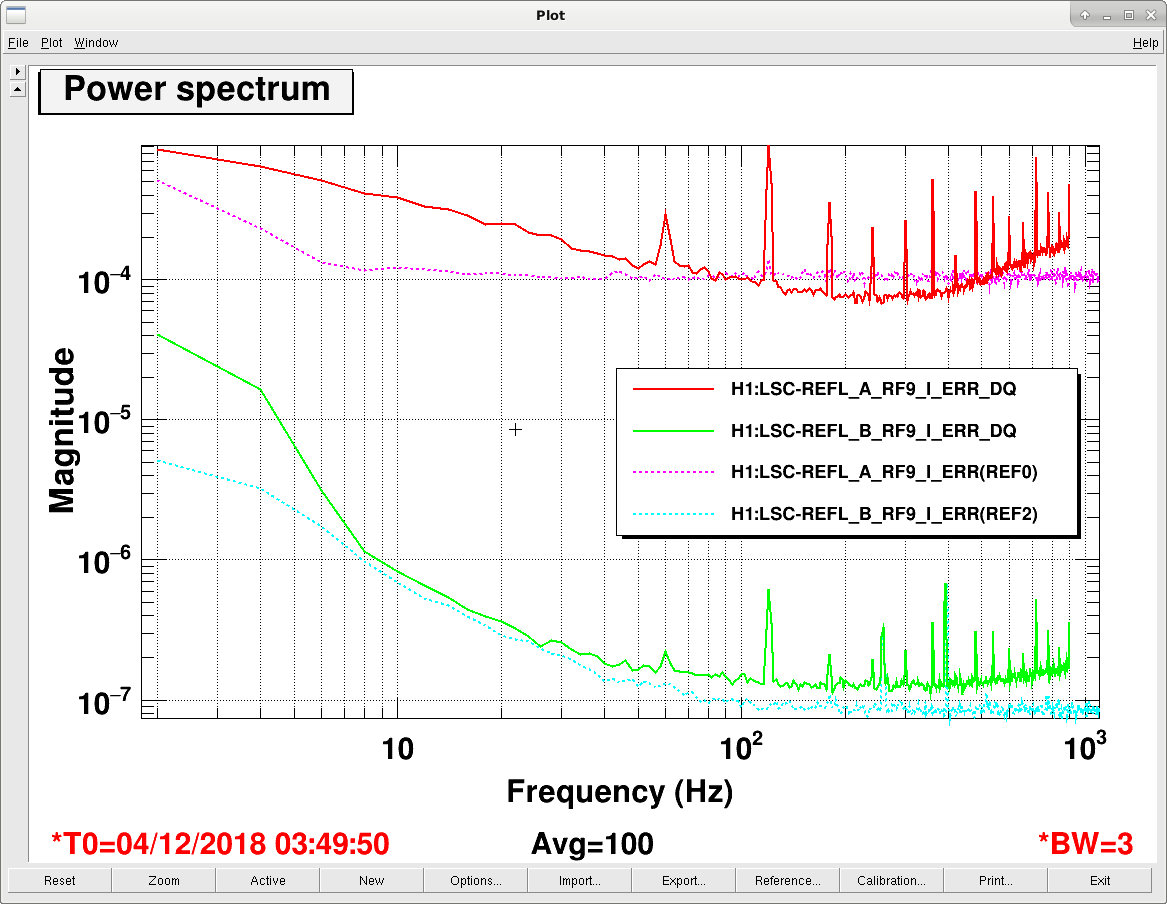
H1:LSC-REFL_A_RF9_I_ERR isn't a particular good witness of frequency noise, see alog 45157. H1:LSC-REFL_B_RF9_I_ERR_DQ seems even worse. Not enough whitening? Slew rate limitations?
OK, indeed REFL_B_RF9_I (green) is limited by the dark noise level (cyan), REFL_A_RF9_I (red) is not as bad as REFL_B but not that great either. At least for REFL_A we can increase the whitening though we might saturate Q phase. These are just readbacks.
Demod phase frequency dependence I don't understand.
Jenne, Hang, Sheila, Stefan
The instability that seems to grow most visible in CHARD actually can occur at two different frequencies: 21Hz and 28.8Hz.
The attached plot shows both frequencies going unstable at the same time. The peaks show up in the REFL DC centering loops and REFL9_Q. I could not find them on any OPLEV or whit ness channel.
We tried to lower the CHARD BW by more than x5, and put notches at the 28.8Hz (0.5Hz wide). None of that made any difference, suggesting that CHARD is just an observer of the problem.
We suspect that the MCL cross-over might have something to do with it. It has an incoherent feature in the transfer function at 29.3Hz. Note that the M2 notch was is off a bit (at 27.45 Hz). We should just disable it. Still that leaves the 21Hz to be explained.
(We once tried to turn off the notch and power up. We only saw the 21Hz instability that time.)
We we lowered the SRC2 PIT and YAW in the Guardian before the PWR-UP to 15 (from 100). Those gains eventually come down to 15 anyway. That seems to have solved the SRC runaway issue.
ITMY mode 8 used to be damped using - gain and no phase shift, now it is damped with positive gain and no phase shift.
ITMX mode 9 used to be damped using no phase and + gain, now it is no phase and -gain. These changes are in gaurdian.
All of the changes that we have had to violin mode phases are on the ITMs, which makes me wonder if it is possible that changing the ring heater settings could change something about the violins.
Not sure the last time someone tried to run an ASC sensing matrix measurement, but it looks like the script didn't properly turn off the 8Hz notches in the DC centering loops. I've turned them off.
Turns out it may not have been the script. The notch filters being on was accepted in SDF. I have turned them back off (after the ASC model restart), and accepted this in SDF.
J Kissel, N. Lecoeuche
While glancing at the PCAL END station overview screens, we noticed that the PCALX screen words "STATUS" and "Pcal modules are not powered" were blinking rapidly. The channels that this status indicator are measuring are:
"Pcal modules are not powered"
H1:CAL-PCALX_LASERENABLE
H1:CAL-PCALX_LASERPOWERCONTROL
H1:CAL-PCALX_SHUTTERSTATUS
H1:CAL-PCALX_LASERDIODECURRENT
"STATUS"
H1:CAL-PCALX_TRANSMITTERMODULETEMPERATURE
H1:CAL-PCALX_RECEIVERMODULETEMPERATURE
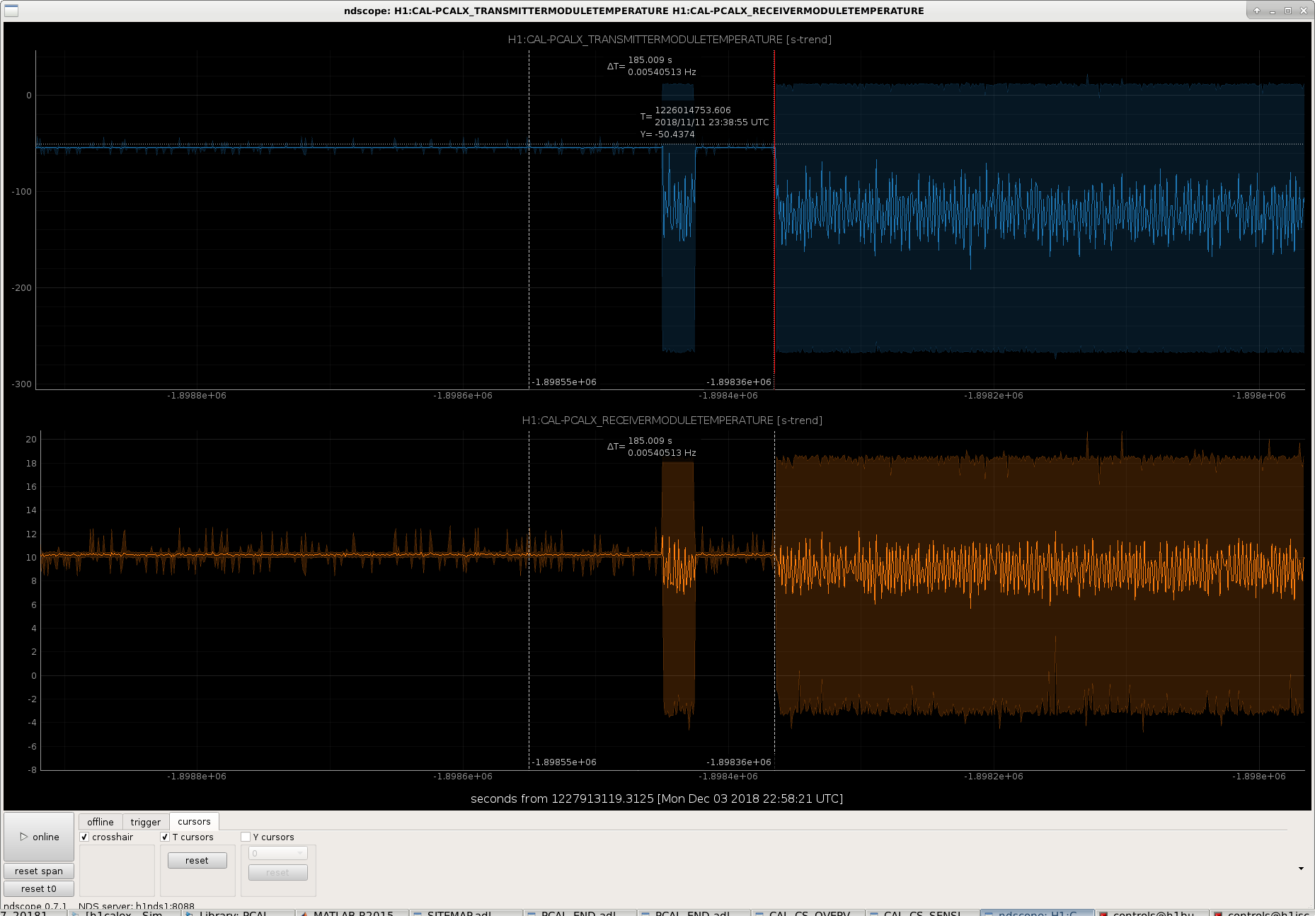
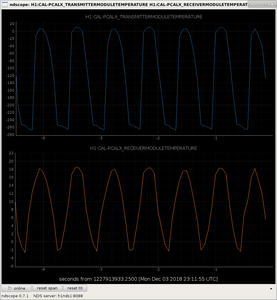
While the "Pcal modules are not powered" channels are flat and unchanging -- and the same as PCALY -- we found that the "STATUS" channels, i.e. the temperature sensor channels, were reporting a wildly oscillating temperature from 0 to 20 deg Celsius, with a ~1 sec period.
This junk has apparently been happening since Sunday Nov 11 2018 (~a month ago) at 23:38:56 UTC (Nov 11 2018 15:38:56 PST).
Attached are screenshots of when the failure happened, and how the sensor outputs currently look.
Opened FRS-11921
This is a known issue. The parts have been ordered to fix this. I will mark FRS as duplicate. It is in the chassis not the readback chain.
https://services.ligo-la.caltech.edu/FRS/show_bug.cgi?id=10987
Tomorrow there will be a big update to the BSC-ISI and SEIPROC models. This is mostly to get code to smoothly ramp between different sensor correction filters and get the ground common mode signals into the ISIs. The former should make it smoother to switch between different seismic configurations. The latter is an attempt to improve isolation and reduce drives during earthquakes, something seismic group has talked about for a while.
Part of this update will include a simplification to how the ground sensor calibration and distribution is done. Currently all of the corner ISIs receive the 3 STS2s from a distribution chassis, and each chamber applies the same calibrations on all 9 channels. The update will use the ITMY ISI to send the uncalibrated signals to the SEIPROC model, which will do the calibration, then send that calibrated signal back out the ISIs. SEIPROC will also take over the BLRMS channel calculations.
I'm documenting what I had to do for the corner station ISIs here.
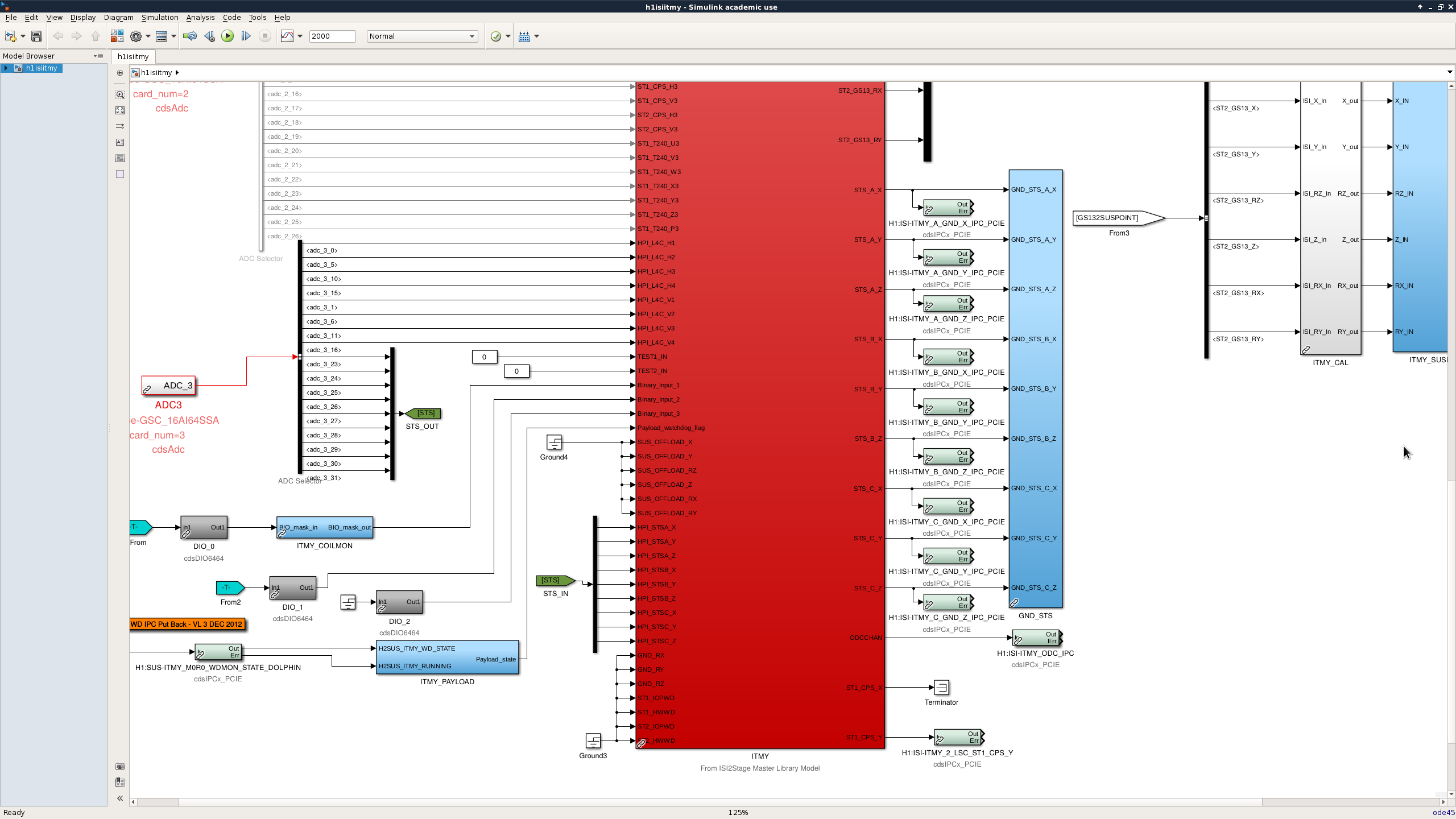
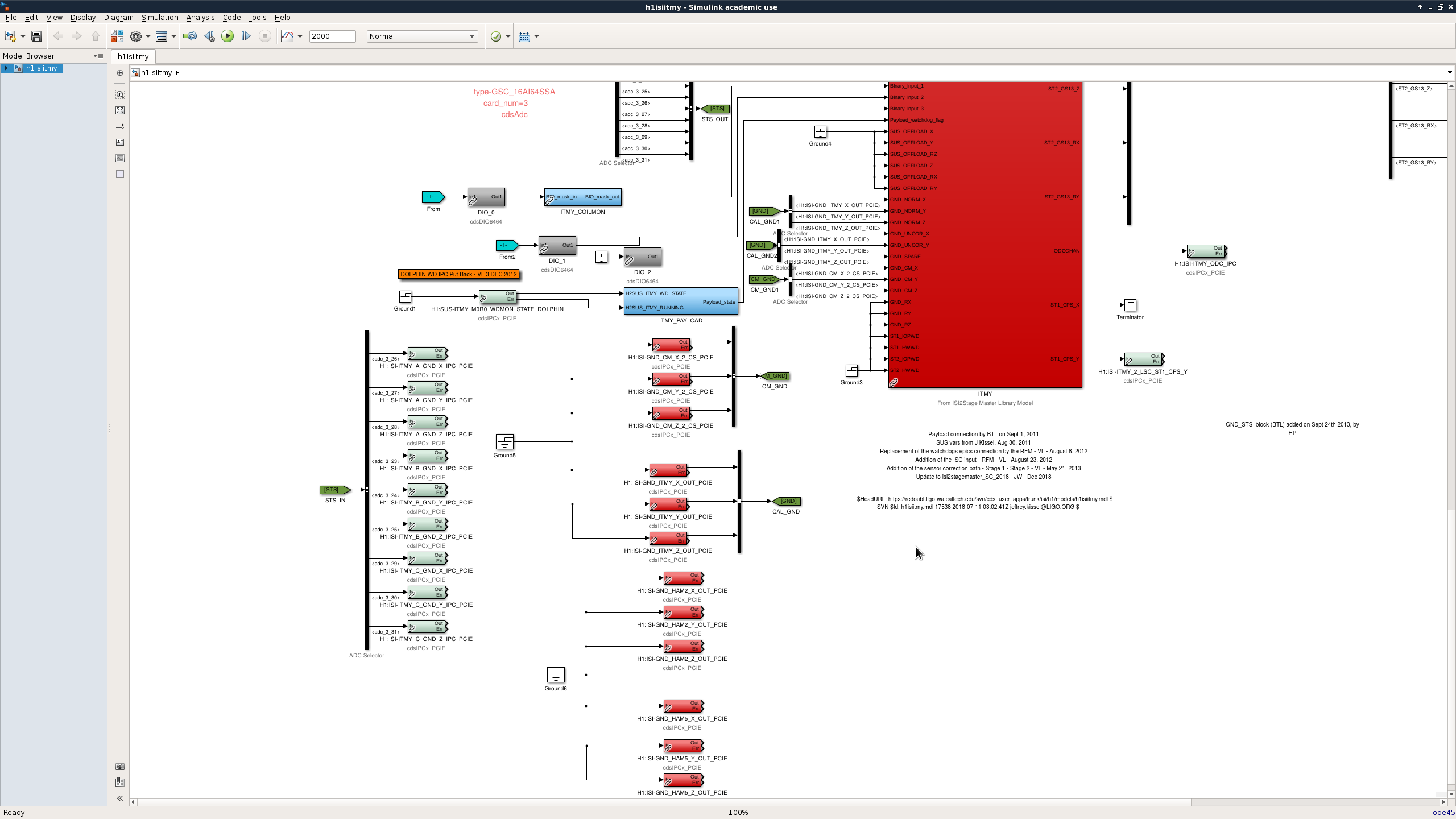
First screen shot, for ITMY I removed and the top level ground block which did the calculation of the ISI-GND_STS_HAM2/HAM5/ITMY calibrated STS channels. This block got moved to SEIPROC.
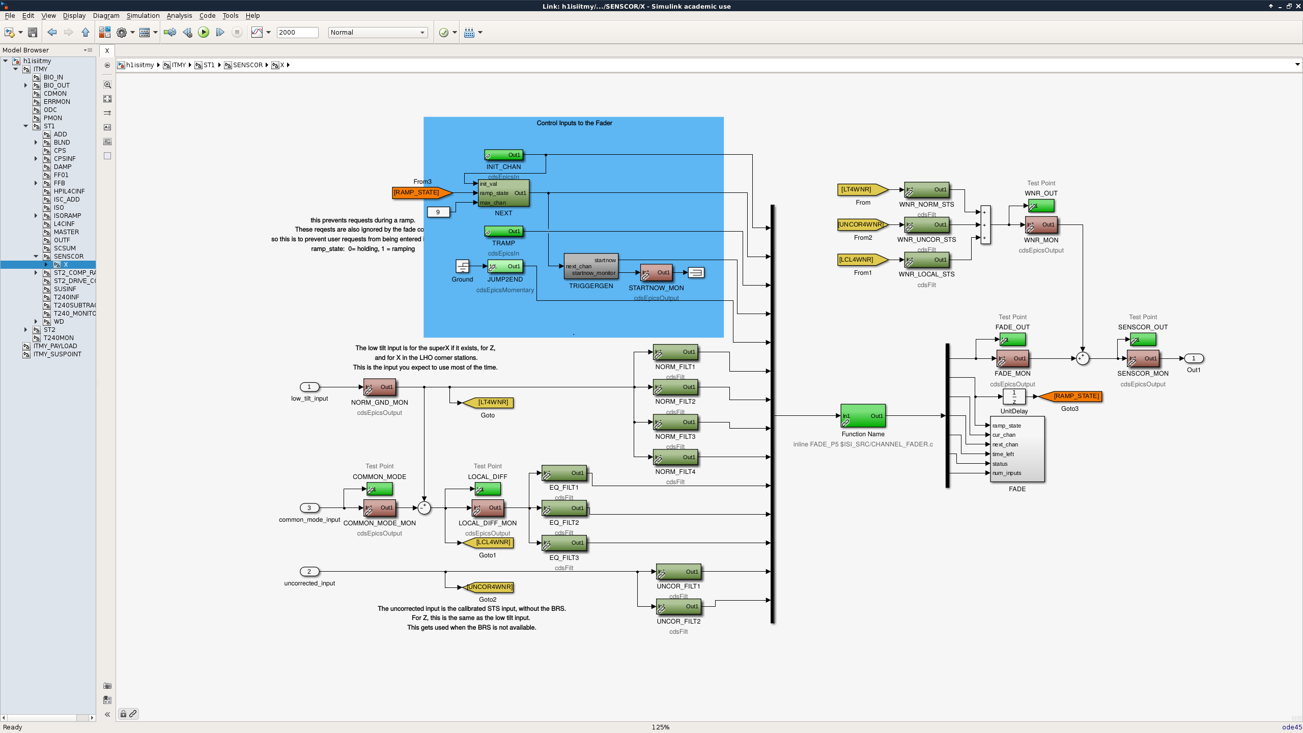
Second screenshot is the update to ITMY ground in. The green STS tag connect the adc inputs through a bus to IPC channels, of the form H1:ISI-ITMY_A_GND_X_IPC_PCIE, these go out to the SEIPROC model. The calibrated IPCs come in to the STS_CAL tag, the common mode signals come in on the CM_GND tag. Current all of the BSC models are set up to just use the ITMY STS (connected to the STS_CAL tag), but it might be a good idea to use some version of the current STS sensing matrix so that we can change which STS we use for feed forward on the fly by changing an epics variable. Both the STS_CAL tag and CM_GND go into the master model to the h1isiitmy ITMY ST1 SENSCOR DOF block, contents shown in the third screen shot. This uses the code outlined in T1800414. There is also a new isi master part, the inputs are mostly the same, but there are fewer outputs because there is now need to ouptut the STS signals on the top level.
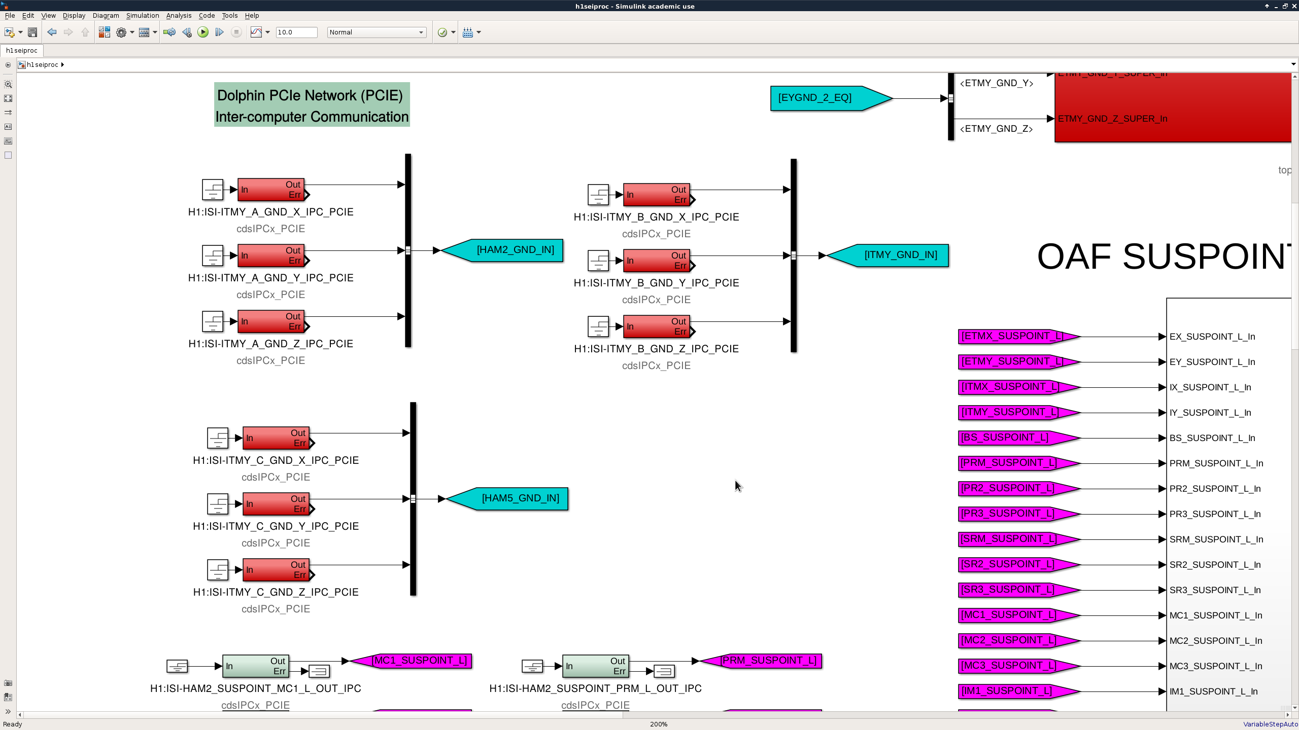
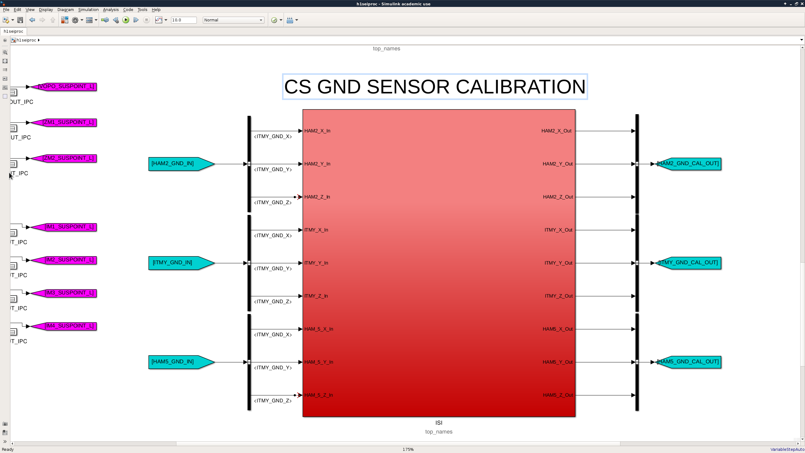
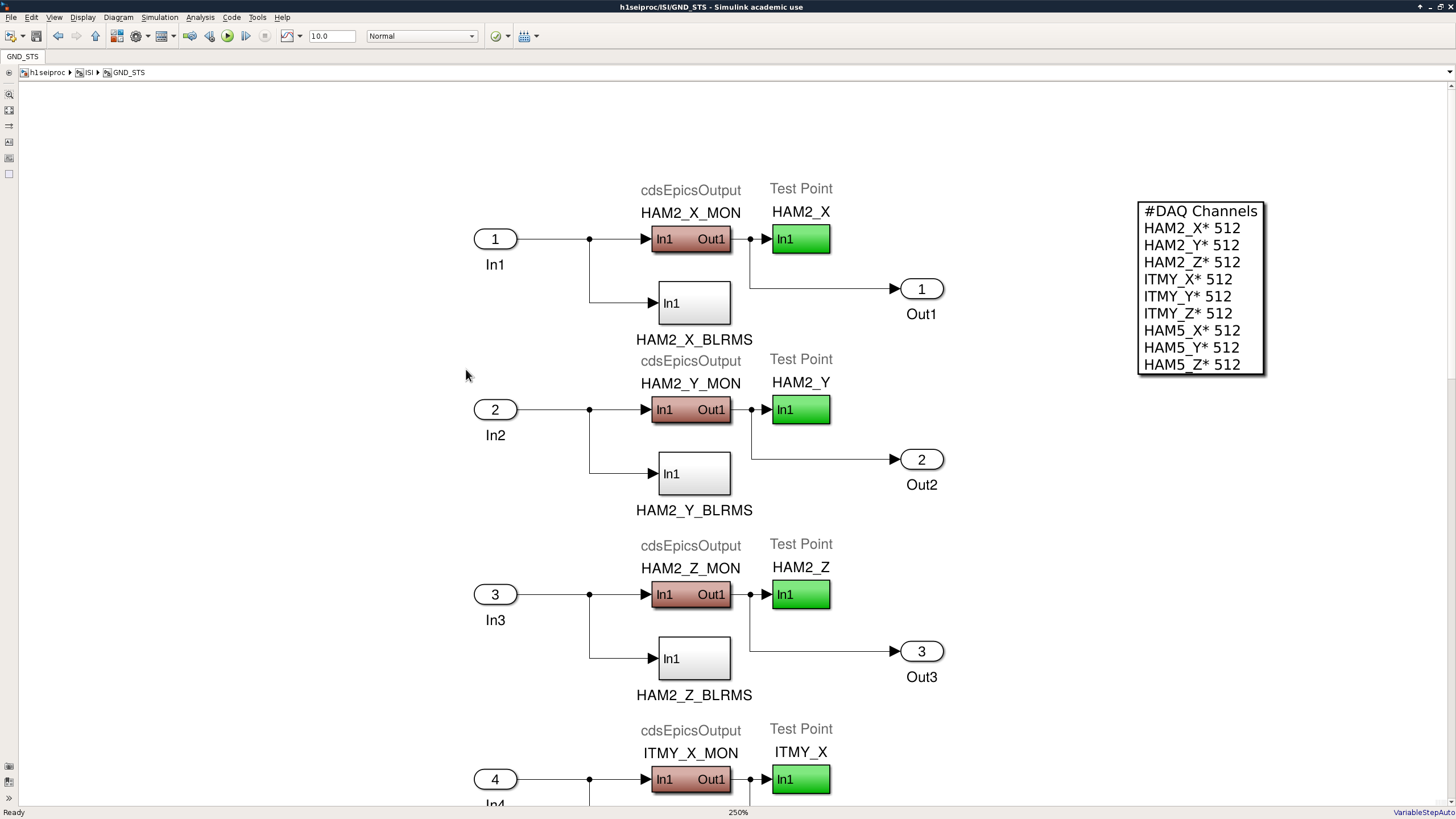
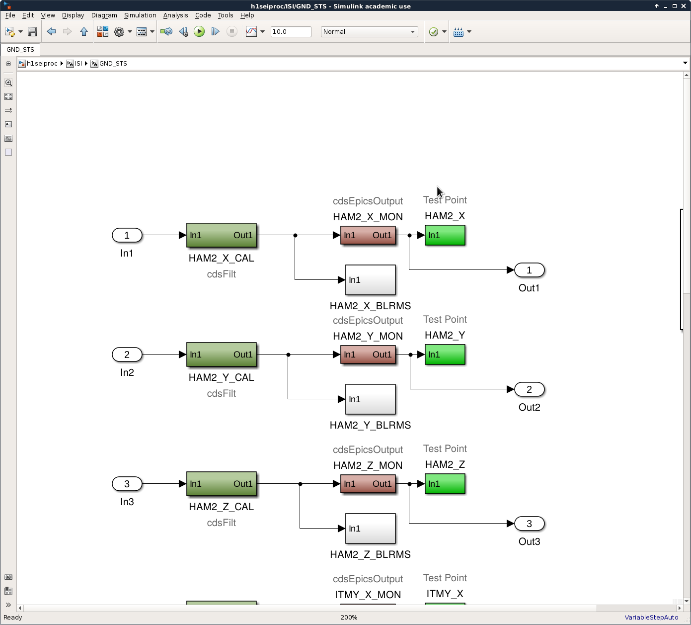
Fourth screenshot shows the uncalibrated IPC channels coming into the SEIPROC model, fifth shows the new, topnamed ISI block for the generation of the calibrated ground signals. This preserves the ISI-GND_STS channel names, so should not affect anyone who uses these channels. The signals are calibrated using mostly the same stuff that the ITMY model used, and include the BLRMS calculations, shown in the sixth screenshot. I will probably have to make a new MEDM to access the STS calibrations, though.
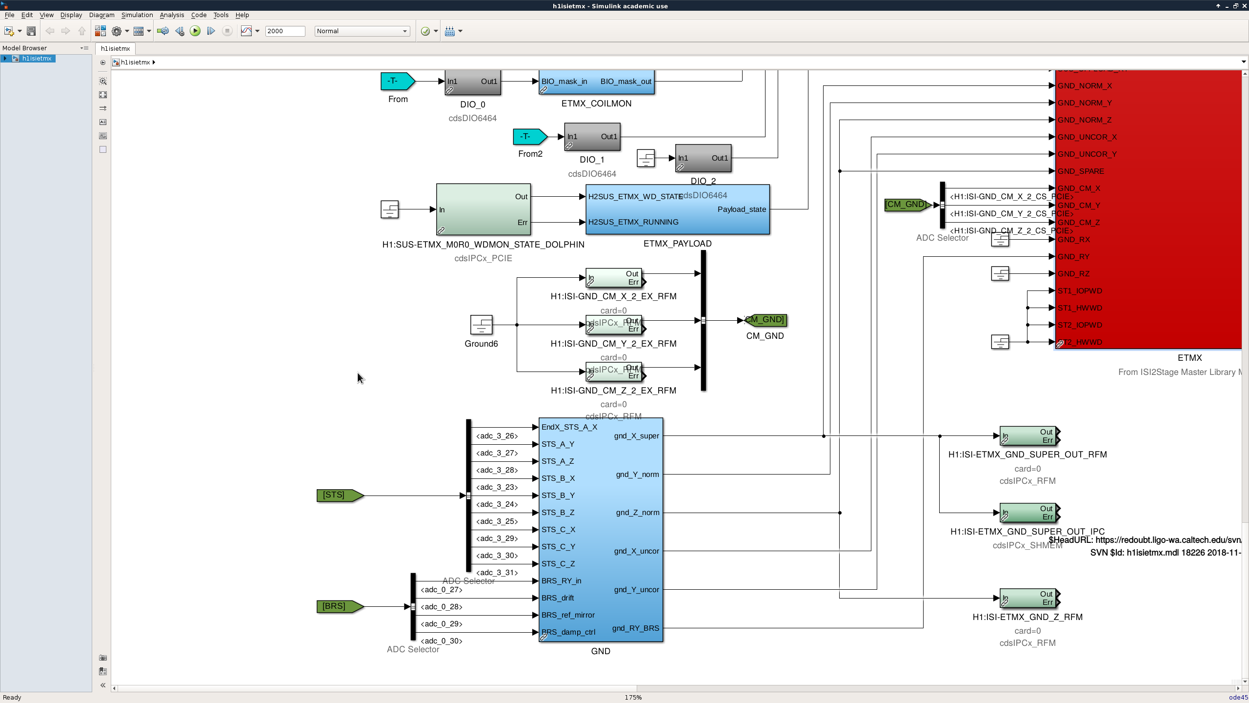
This update also applies to the endstations, but the STS calibration is done in a block added to the top level. I added this block a couple weeks ago, which required deleting a block like ITMY and stuff on the top level for the BRS subtraction, then wiring up a new block that organized it all in a library part. This change is shown in the seventh screenshot. The endstation ISIs are also getting the common mode signals from the corner.
The HAM-ISI models now also have this update ready to go, it's a bit simpler to install. The BSCs will get installed & restarted tomorrow, the HAM and HEPI updates will go in next week.
I forgot to add filter banks to allow for calibration of the STS signals in the SEIPROC model. Those are in now, the banks will be of the form H1:ISI-GND_STS_HAM2/ITMY/HAM5_X/Y/Z_CAL (I just realized that BrianL had already created some screens I could reuse if I was smarter, and used channel names like H1:ISI-GND_STS_HAM2/ITMY/HAM5_INF_X/Y/X). After Dave restarts the h1oaf, I'll make an screen to make the interaction with these banks easy.