TITLE: 11/12 Day Shift: 16:00-00:00 UTC (08:00-16:00 PST), all times posted in UTC
STATE of H1: Corrective Maintenance
INCOMING OPERATOR: None
SHIFT SUMMARY:
LOG:
16:15 Switched Observatory mode to 'Corrective Maintenance'
16:20 Hugh, Jeff J and Charlie out to LVEA
16:21 Fil out to ISCT1 to disconnect cables for moving.
16:25 Gerardo out to LVEA - Output
16:29 reset HAM6 ISI WD
16:46 Hugh, Charlie and Jeff J out
17:00 Just notice Rick in PSL enclosure
17:01 Bubba out to LVEA
17:09 Jeff B out to PSL
17:12 Richard just informed me that the Safety Interlock system is tripping due to a flaky cable at ISCT1
17:13 HAM6 vented and door(s) being prepped for removal
17:15 Chandra out to EY to prep for afternoon vent
17:24 Sheila and Fabrice out to HAM6 area
17:26 Chris S out to LVEA - door removal
17:27 Hugh out to LVEA
17:30 Cleaning crew out of LVEA
17:41 Cheryl back
18:01 set all sus in HAM6 to 'SAFE' - ZM1 is duplicated in main GUARD_OVERVIEW screen
18:02 Cleaning crew and Hugh out to EY
18:13 Gerardo and Kyle back
18:15 Fil back
18:30 Gerardo out to EY
18:45 Chris and Bubba back - removed end cap on HAM6
19:41 Corey out to LVEA - signature for WP and search for lexan viewport cover to move ISCT1
!9:50 Corey brought back WP for operator signature - back out to LVEA to prep ISCT1 for move
20:06 Jeff B and Peter K out
20:06 cleaning crew back from EY
20:30 Rick out of PSL
20:53 Richard out to LVEA - looking for Fil
21:00 E Stop faults reset
21:19 Gerardo, Kyle, and Chandra out to LVEA - they will begin to vent HAM1 ahead of schedule - doors will stay on for now
21:22 Chris S out to EX - greasing in fan room
21:28 Chandra back and out to EY to begin vent
21:53 Jason and Peter out to PSL
21:58 Bubba out to LVEA - checking area to set HAM1 doors
21:58 Hugh out to LVEA-locking HAM1 HEPI
22:05 Dave Barker out to End Stations -checking comps to see why sei won't reset
22:15 HAM1 vented - VAC team out to EY
22:22 Fil and Richard back
22:41 Chris S back and out to LVEA
22:42 Sheila, Haocun, Nutsinee, and Fabrice out to HAM6 - Squeezer table
23:13 Jeff J out to LVEA - checking status of work
23:20 Dave Barker back
23:33 Jeff J back
23:37 Daniel and Dan to EX - Hartman table work
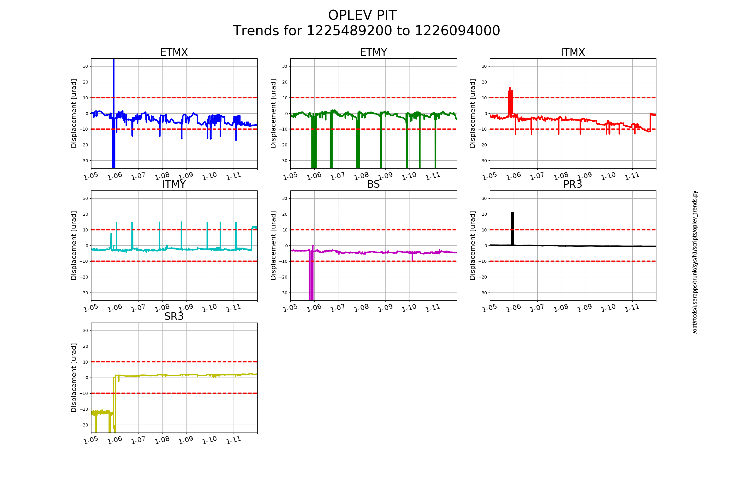
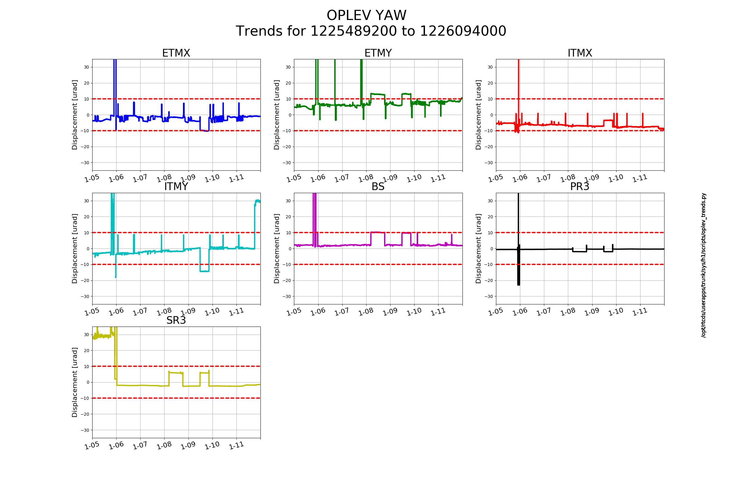
PIT alignments have been nominally good. The deviance at the earliest point in the trends on ITMX and ITMY I'm going to attribute to the vent work.
I'm going to say that's a ditto for the ITMY YAW.
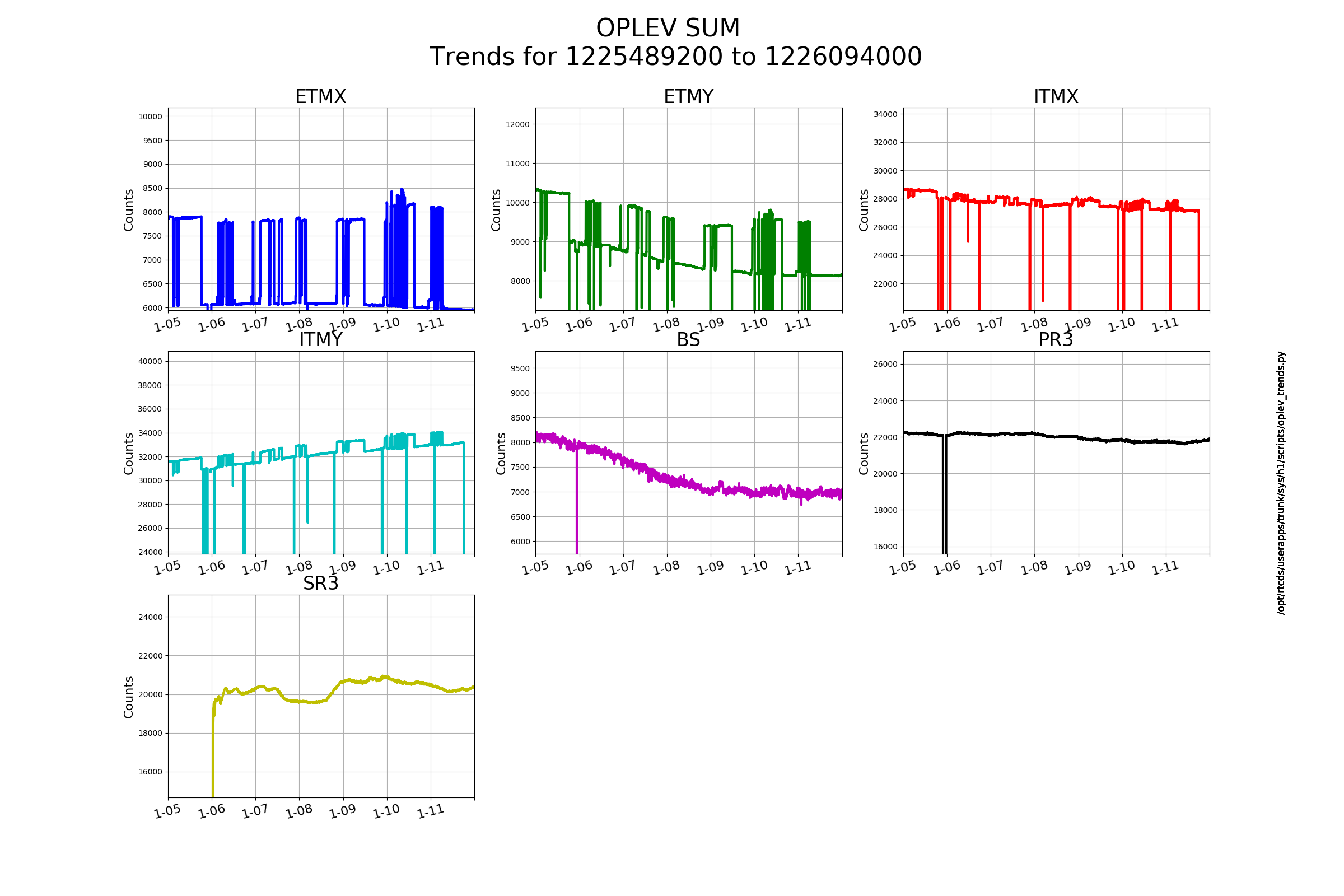
Not sure what to say about the sums. They are affected by the ever-slightly changing alignment(s). None of them show imminent death though the counts on the ETMs are historically a little lower than the rest (except for the BS)
Laser Status:
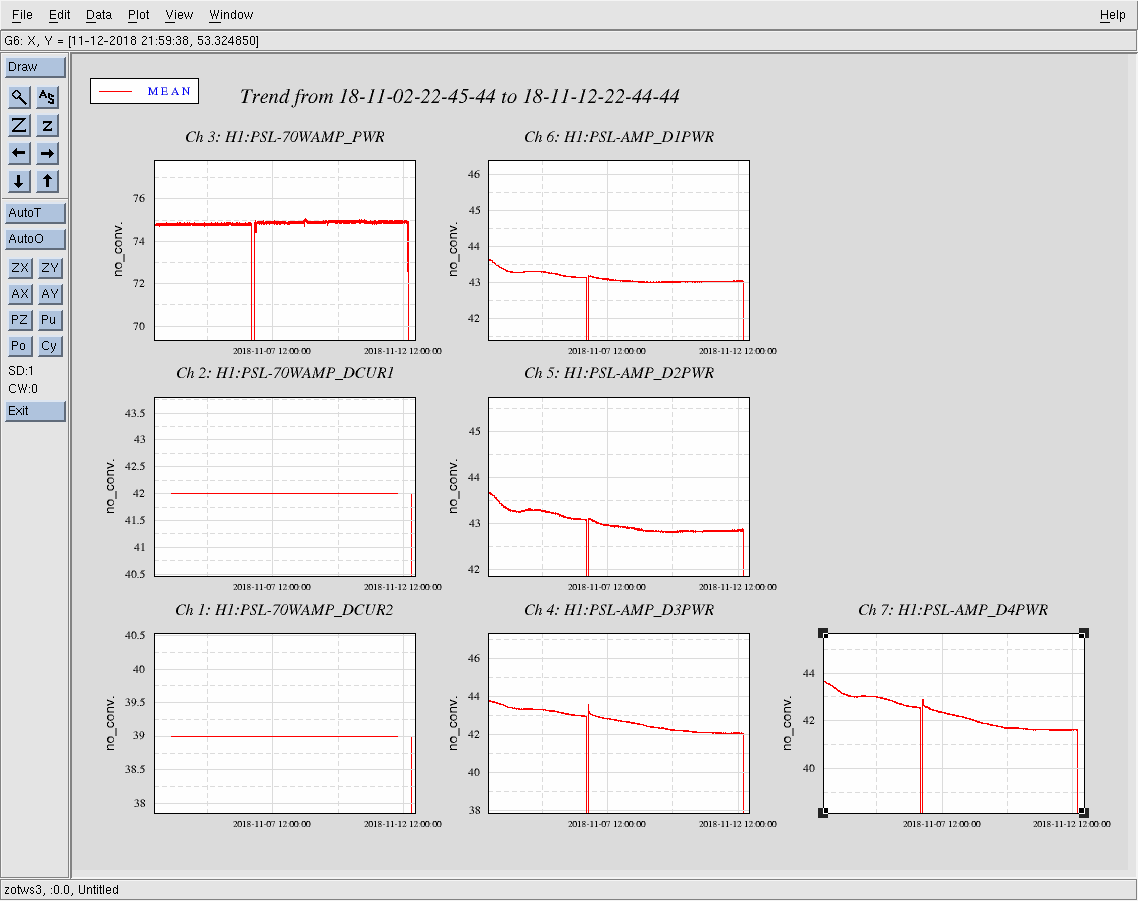
Front End Power is 0.01014W (should be around 30 W)
70W Output Power is 2.425W
Front End Watch is RED
70W Watch is GREEN
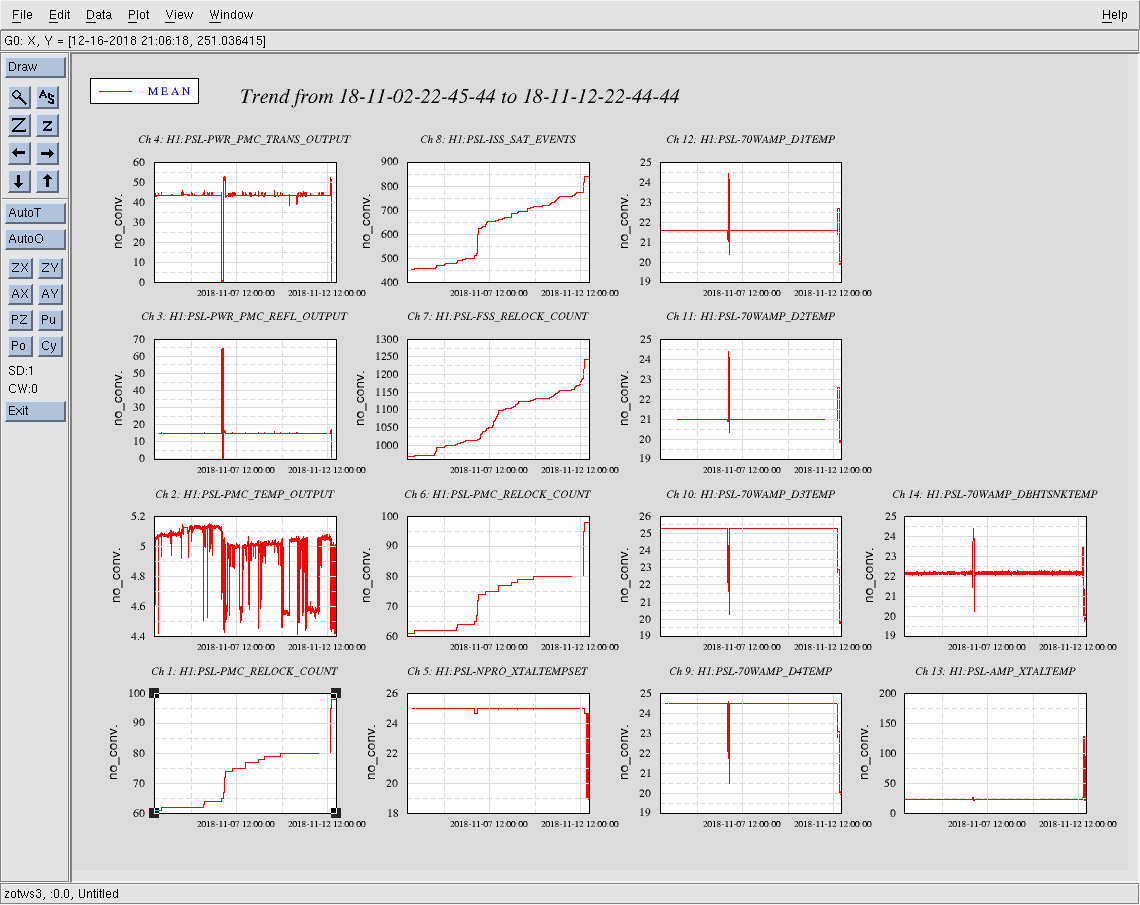
PMC:
It has been locked 0 days, 0 hr 0 minutes (should be days/weeks)
Reflected power = 0.0367Watts
Transmitted power = -0.0226Watts
PowerSum = 0.014Watts.
FSS:
It has been locked for 0 days 0 hr and 0 min (should be days/weeks)
TPD[V] = 0.04675V (min 0.9V)
ISS:
The diffracted power is around 0.14%
Last saturation event was 0 days 6 hours and 34 minutes ago (should be days/weeks)
Possible Issues:
Vent activities this week including but not limited to: Mode matching work, 70W amp remounting, plumbing work, and IO work
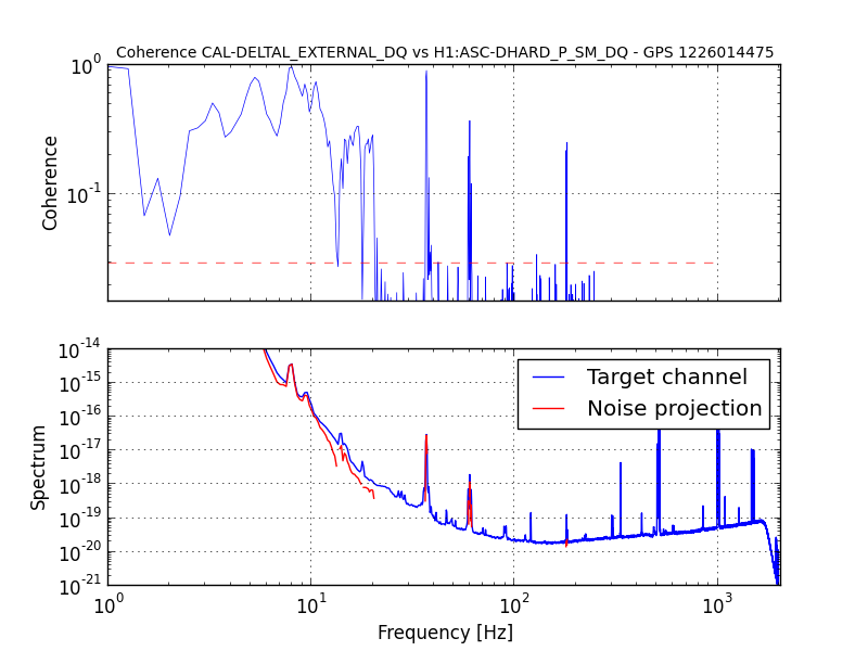
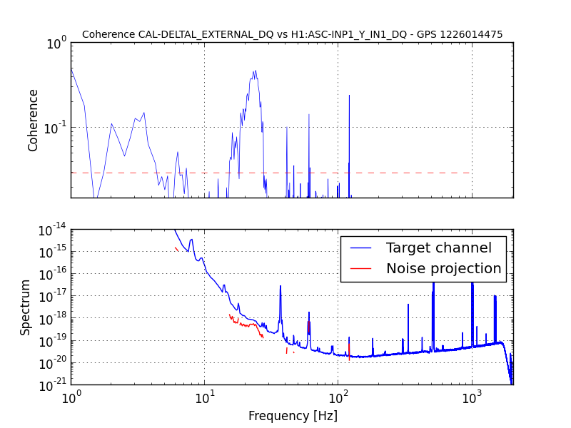
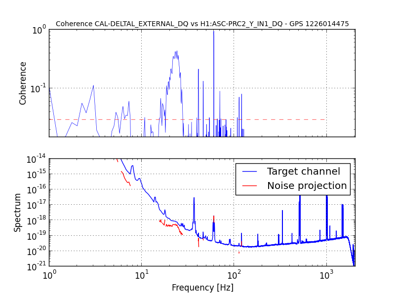
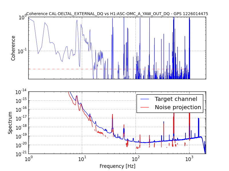
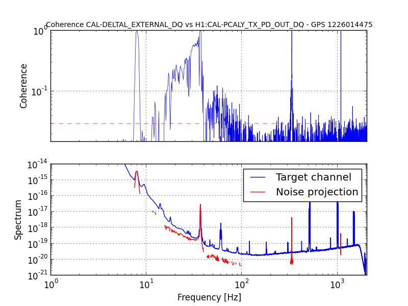
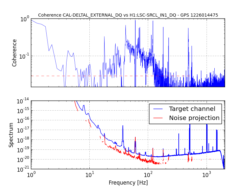
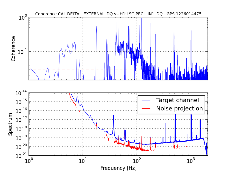
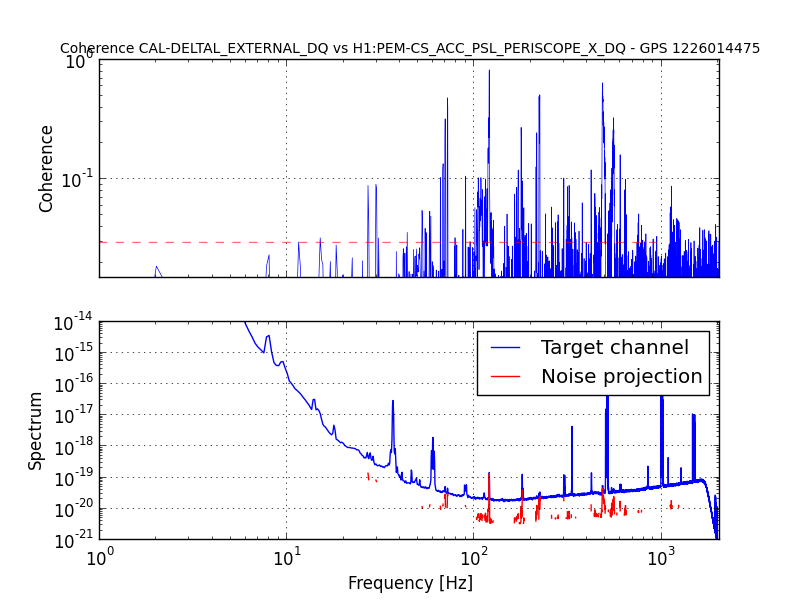
https://ldas-jobs.ligo.caltech.edu/~gabriele.vajente/bruco_1226014475/
Thanks Gabriele, this will be useful. Just want to say for the record that the calibration was wrong during this time, we don't believe our sensitivity was really 100 Mpc.
Too bad, that would have been good. Nevertheless, the coherences are still significant and similar to what reported for earlier lock stretches.
The Pcal lines at the Y-end were turned on at ~1226014752.1 GPS sec (around 277.1 sec after the start of this bruco run) and there was no ramp up of the amplitudes of the lines. The high coherence we see around 30 Hz with PCal singal seems to come from sudden turn on of the lines and also due to spectral leakage. If I calculate the coherence for the first 270 secs or last 120 secs I don't see any such excess coherence.
Based on a relatively quiet stretch, before the IMC lost lock, 1226067950 to 1226067960. Plots showing the Bullseye and IO signals attached.
PeterK, JeffB, RickS
This morning, Peter set irises to mark the beam pointing in advance of the water line work.
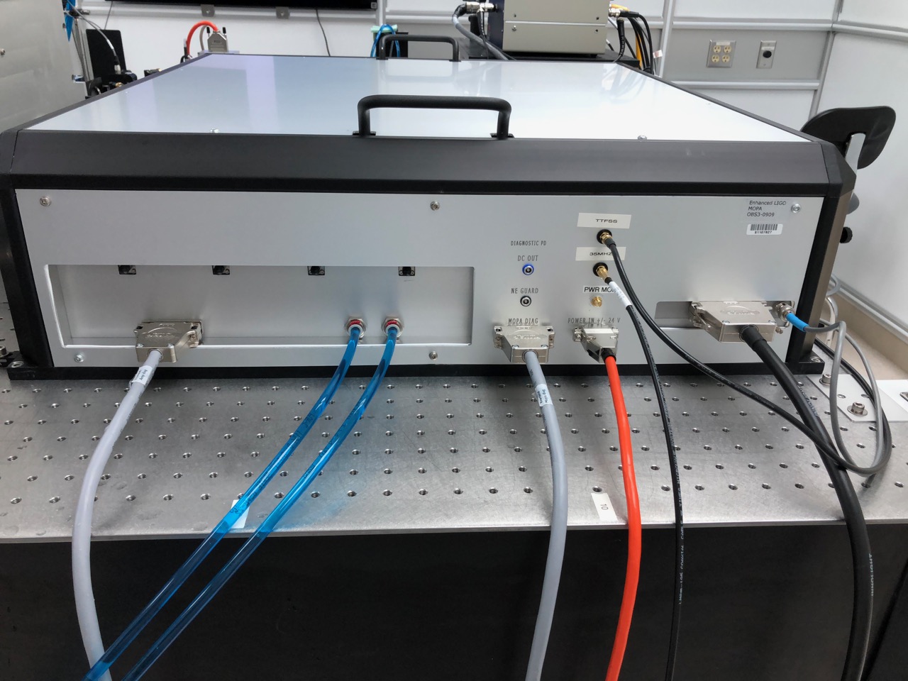
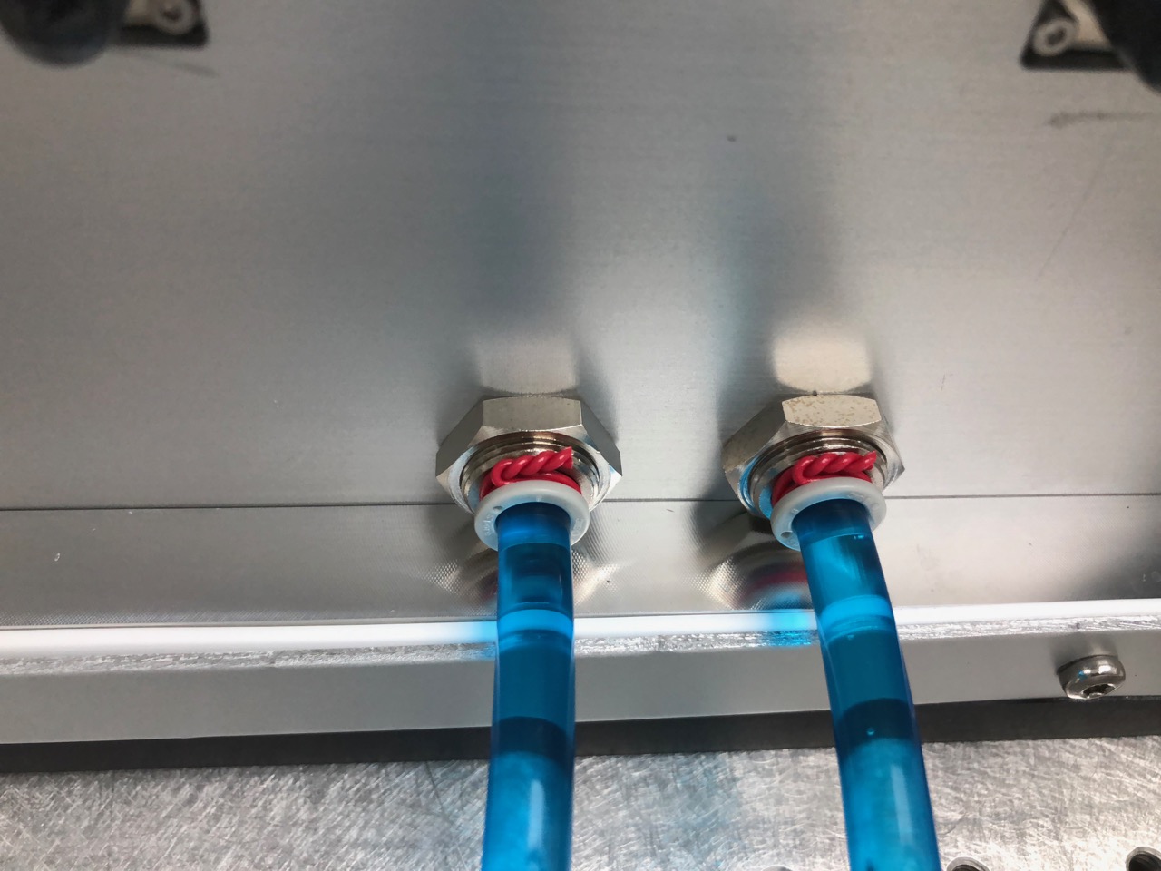
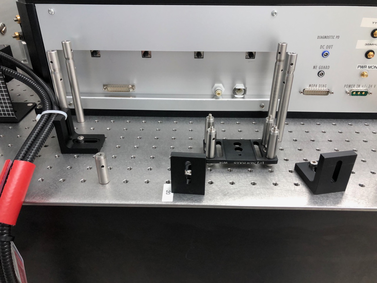
We then installed stops to register the position of the Front End baseplate, removed the pump fibers, moved the Front End box to the edge of the table, removed the 35-W amplifier from the Front End box, and replaced the "quick connect" water fittings with 8 mm push-to-connect tubing fittings (see attached photos).
We did a pressure test with the 35-W head plumbed in the new configuration but outside the Front End box to check for leaks before re-installing it and moving the Front End box back into location.
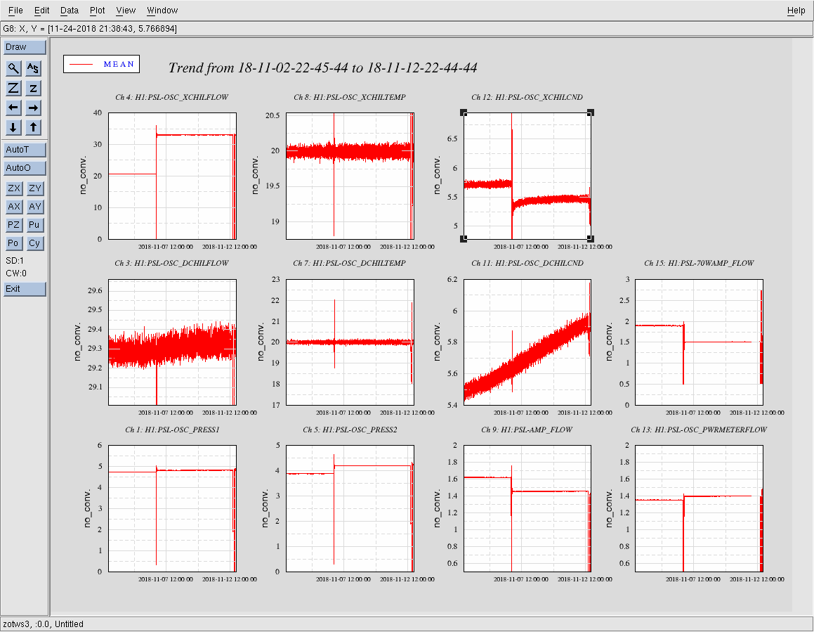
We also removed all the flow-regulating valves from the supply-side water manifold for the three circuits: 35-W amp, 70-W amp, and high-power shutter. We moved the flow meters to the return-side manifold so that they would respond to a leak in the water path by shutting down the chiller before exhausting the water supply.
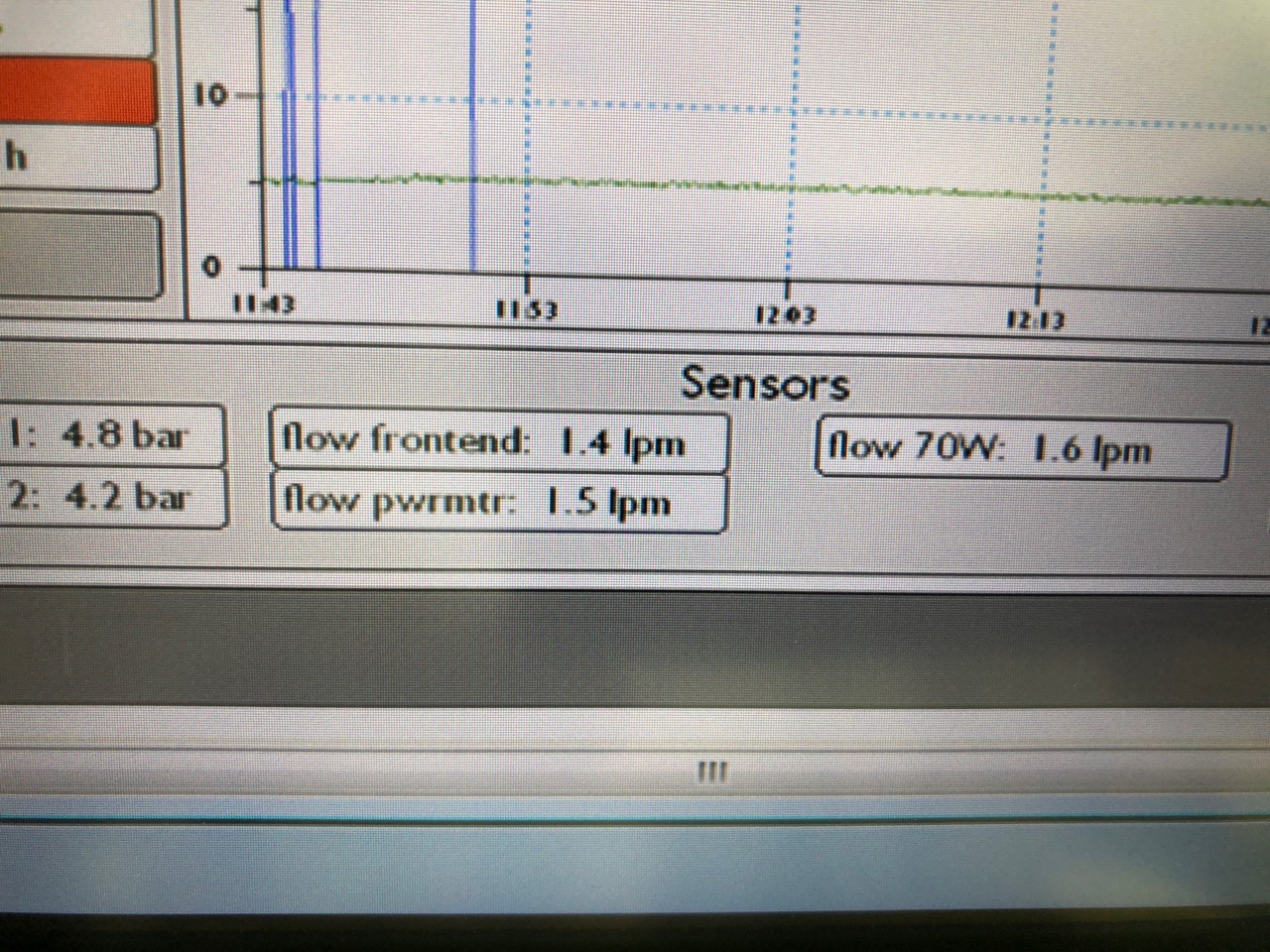
Initial flows were: 1.3 lpm, 2.7 lpm, and 1.4 lpm for the three paths. We then installed a 3-4 ft. section of 6 mm (OD) tubing in the 70-W amp path. The resulting flows were: 1.4, 1.9, and 1.4 lpm. So we added about 40 ft of 8 mm tubing (we didn't have any more 6 mm tubing) to get flows close to the 1.5 lpm target: 1.4 lpm, 1.6 lpm, 1.5 lpm (see attached photo). Note that the "pwrmtr" signal is really for the HP shutter).
Note that we have not yet modified the chiller configuration to reduce the laser-end water pressures, now about 70 psi on the supply side and 50 psi on the return side, by throttling the chiller output to reduce the pressure drop across the heat exchanger on the return-side path to the reservoir. We plan to do that later in the week. We are waiting on a part that is schedule to arrive today or tomorrow.
Our detailed task list is also attached for future reference.
With PSL being down this morning replace and cleanup fiber cabling in the MSR and CER. This work effected both the Safety and Slow Controls systems.
In preparation for ISCT1 being moved, field cabling was disconnected this morning.
I have adjusted the tuning parameters at EX, namely the Proportional and Integral on the Face-Bypass Dampers to try and slow the temperature swings. Although we are still maintaining the desired temperature, the swings are apparently to severe for the BRS.
Carlos, Dave
We have installed the new computer in the rack slot formerly used by h1auxscript0. It is unclear that this aux machine was actually doing anything, so we may leave it out of the rack for now. The new video server will be called h1digivideo3 and run Debian9.
The updated mode-matching solution to account for the noise eater alog(44783) assumed a waist at the coupler of 750um (because that was in the thorlabs documnentation recommended). However a measurement indicates a waist of 500um out of the coupler.
I adjusted the solution SHGtoFiberAM.pdf alog(44783) to move the ROC75 lens 6cm closer to the SHG the ROC200 lens 1-2 cm further away from the SHG and the fiber coupler 10 cm further away from the SHG to get a waist of 550um.
To get a waist of 500um would take a relatively major path rearrangement and with the vent only hours away it was a little risky to do it now, I will fine tune after the vent and hopefully the proper solution will be significantly above 85%.
Turned ON air compressors in chiller yard for instrument air, QDP80 is ON, and purge air skid is ON.
Hard closed GV 1,2 this morning and then vented HAM6 (~45 min. vent). Dew point measured -45degC just before valving in purge air.
Inserted pins on GV 1,2 gates, but LOTO at power disconnect.
IP14 on HAM6 had tripped a few minutes before venting. Either HV cable was bumped during chamber cleaning or gas load from compressing o-ring on gate valve exceeded tight pressure interlock. After a couple of hours being off, it turned back on with no problems.
I've put in a temporary bypass for HAM6. We'll bypass others as the vent progresses.
Bypass will expire:
Tue Nov 13 08:36:07 PST 2018
For channel(s):
H0:VAC-LX_Y0_PT110_MOD1_PRESS_TORR
Extended bypass to include HAM1 (PT100) as well as HAM6 (PT110)
Bypass will expire:
Mon Nov 19 13:41:43 PST 2018
For channel(s):
H0:VAC-LX_Y0_PT110_MOD1_PRESS_TORR
H0:VAC-LY_X0_PT100B_PRESS_TORR
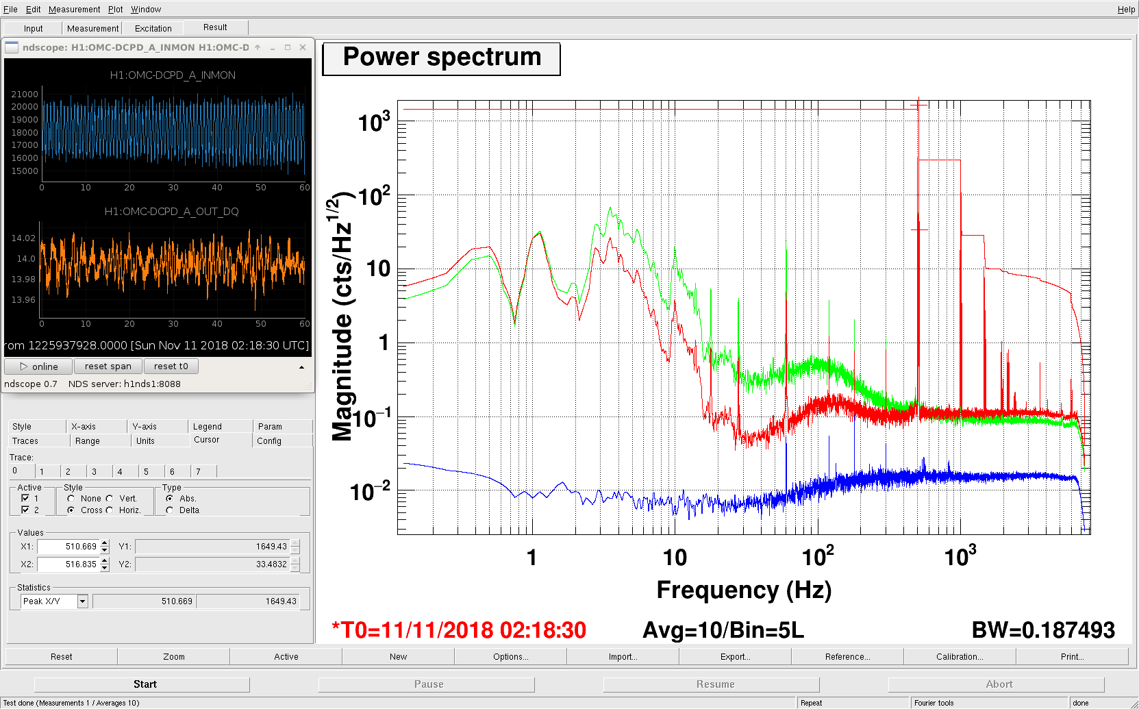
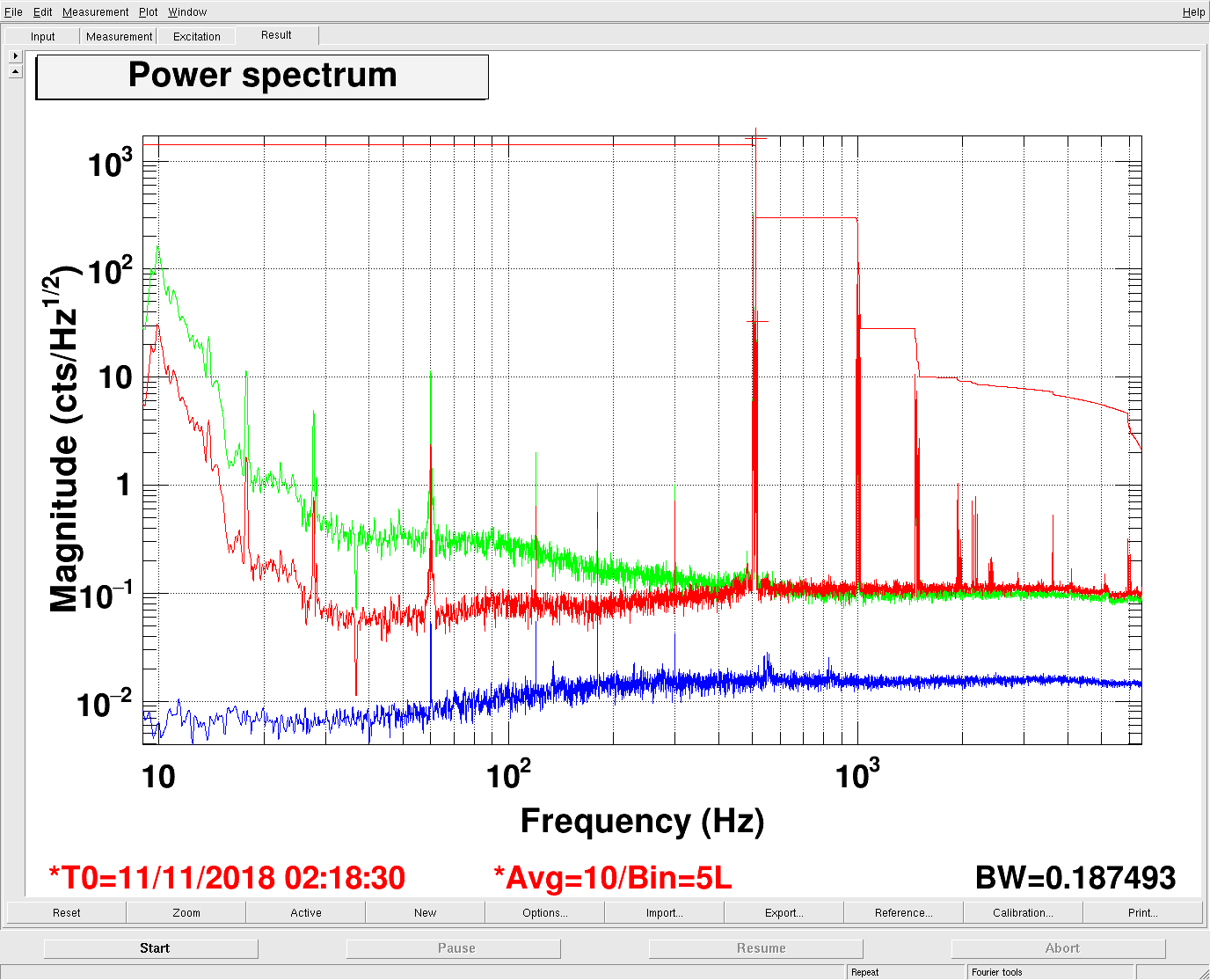
We observed some improvement with larger PD current yesterday. It was not clear to us why. There is some chance that a calibration issue is fooling us, but at the low frequencies we were looking at the calibration should only depend on the actuator. Either way, to get to the bottom of this, we revisited the whitening of those PDs. Currently, we are using 10mAmp per diode in regular operation. If the violins are smaller (as the were yesterday) we can increase the DARM offset to operate at about 15mAmp per diode, but that becomes a problem when the violin modes are high. Attached is a plot of the whitening situation of out OMC DCPDs in full lock, with about 14mAmp per photo diode. ndsope inset top: ADC signed of the photo diode ndsope inset bottom: photo current on the photo diode dtt red: PD signal in cts ADC (which is loop gain suppressed, hence the dip at 30Hz amd the peak at 100Hz) dtt blue: dark noise dtt green: possible option with current whitening filters: additionally engage a 2nd whitening stage plus the low-pass. Reduce the DARM offset by 3.2dB to get the violin mode peaks back down where they were. It would be worth testing the green configuration, just to exclude that we have some load-dependent dark noise after the whitening stages.
Fil Marc Daniel
We modified the spare CM board (s/n S1102622) according to E1800338 and swapped it with the existing one (s/n S1102621). This modification includes low pass filters for the DAQ readbacks, and a frequency change in the first two boost stages to 10Hz/500Hz.
These modifications improve our readbacks. Previous data is in alog 45131.
Fig 1 shows the readbacks of the modified board.
Fig 2 shows the new 10/500Hz analog boost filter. The RMS of the error signal gets reduced by ~400.
Looking at one of the higher power runs with a REFL fast gain of +24dB, IMC IN2 gain of -24dB and a REFL IN1 gain of 9dB, we can see that both error and control signal readbacks show again excess noise. The fast/in2 gains may be too high and we should try 16dB instead. Not sure what's up with the error signal readback, maybe too much in-loop gain with the additional boost.
The figure shows spectra from the 4 angular IMC WFS DC channels with labeled peaks. Eight of the peaks between 80 and 1000 Hz are from optics or structures on the PSL table, two were from IOT2 and four haven’t been identified. The unidentified peaks were not excited by our PSL injections, even the global ones. It is possible that they are associated with structures that weren’t excited on IOT2 or in HAM2, or they may be associated with structures on the PSL table that we weren’t able to excite.
The identified sources are table resonances, periscope resonances and optic mount resonances. All optics that produced peaks in the spectrum were downstream of the PMC and were mirrors rather than through-optics like lenses, as would be expected.
The figure also shows the location of the sources in the PSL, as well as samples of the bowing and tapping data used to make the identifications.
Robert, Craig
This version of the jitter spectrum includes photos of the optics. It should be easy to lower the Q of some of the higher-Q optics like M3.
This is a very interesting and impactful glimpse into the current state of PSL table jitter coupling. Wish I had noted the study on first release.
I'm sure many would be interested in seeing an equivalent study of LLO, in everyone's spare time
.
This study is relevant to IIET Ticket 4639 with title: "ECR: Modify attachment of optics mount to mounting plate on PSL periscope, previously Bug 1140". This IIET Ticket corresponds to the upper periscope mirror mount, with designator IO_MB_M6.
This study is relevant to IIET Ticket 5132 with title: "Move IO input beam PZT-mount from periscope to PSL/IO table surface". This IIET Ticket corresponds to the steering mirror upstream of the periscope which has a PZT actuator, with designator IO_MB_M4.
This effort was subsequently re-examined by Robert in
https://alog.ligo-wa.caltech.edu/aLOG/index.php?callRep=44460