yannick.lecoeuche@LIGO.ORG - posted 08:41, Monday 26 March 2018 (41143)
PSL Weekly Report
FAMIS 7483
Laser is off at the moment, no meaningful data in generated report.
FAMIS 7483
Laser is off at the moment, no meaningful data in generated report.
Summary: I attempt to roughly rank the DARM noise contribution from glints seen in photographs taken from the point of view of beam spots on various optics, in order to inform decisions on stray light mitigation. This ranking is based on the assumption that many of the locations that retro-reflect light scattered from a beam spot similarly reflect the camera flash. The glints are weighted according to estimates of the power on the optic, of the coupling of scattered light to DARM at that location, of the fraction of light scattered towards the glint site, given by updated estimates of optic BRDF, estimates of the solid angle of the glint, and estimates of the distance to and motion of the reflector. The highest ranked glint was the glint from the pre-mitigated P-Cal periscope, suggesting that the ranking is reasonable. The next highest rankings were glints from the arm cavity baffles, reduction flanges near the ITM optical levers, BS chamber walls, and possibly certain valve seats. This ranking does not account for beamed light from ghost beams, or light that is scattered at one optic and recombines at another optic.
Introduction
A potential source of scattering noise is light that is scattered from the beam spot on an optic to a moving reflector, which then reflects the light back to the same beam spot where it can recombine with the main beam and produce noise as the phase varies with the optical path length. To inventory potential reflectors, I take what I call beam-spot photos, taken with a camera as near as possible to the beam spot so that the photograph records potential scattered light paths, especially those that would reflect light back to the beam spot. Here I attempt to inform the priorities for stray light mitigation by roughly ranking the glints in the beam-spot photos according to how much noise they might produce in DARM.
I use a small camera that can easily and safely be held right in front of the beam spot position on an optic. The flash on the camera is located right next to the aperture so that the light emitted and the light received are at similar locations near the beam spot. The camera is an underwater camera that can be immersed for cleaning.
Of course, there are several differences between the flash and the light scattered from the beam spot. First, the flash and camera image sensors are broad-band while we care about scattered light at the laser frequency. Thus, the flashes are useful for spotting metal and other broad-band reflectors, but the reflection is reduced for narrow band reflectors like many of our optics. Second, the laser light scattered by the optic has a strong angular dependence, while the camera flash is designed to provide uniform illumination.
The glints are ranked according to a weighting factor. I attempt to account for the difference in the angular distribution of the scattered light from the laser and the camera flash by assuming that the flash is uniform and by estimating the BRDF of the optic and incorporating this and the angle to the glint in the weighting factor. The BRDF value is squared in order to account for scattering from the optic and recombination of the retro-reflected light at the optic. The squared distance to the reflector is included to account for the geometrical attenuation of the light from the beam spot.
The weighting factor also includes a rough estimate of the transfer function of scattered light to DARM for the point at which the scattered light is re-injected. The estimate used here is the value of the transfer function at 100 Hz from figures 1 and 2 of https://dcc.ligo.org/DocDB/0008/P1000002/001/P1000002-v1_MG12_scattered%20light%20control.pdf
In addition, the weighting factor includes weights for the relative power of the beam on the optic, and the solid angle of the glint in the photograph. However, I do not account for saturation in the images and variation between pixels: the power/steradian of all glints identified in the photographs are assumed to be equal. While this is not very accurate, I think it is a reasonable first step, considering that other factors, like the transfer functions, cause many orders of magnitude variation in the weighting factors. Eventually it would be nice to calibrate the relationship between pixel values in the photograph and the power incident on the pixel sensor, but I haven’t done that yet (it might make sense to flash in IR before getting to this stage). Finally, the weighting factor includes a rough estimate of the relative motion of the reflector, and assumes that the motion coupling is in a linear regime.
So, at present the rough weighting factor is:
Weight = BRDF^2 * transfer-to-DARM * relative-power-on-optic * steradians-of-glint * reflector-motion * normalization-factor / distance-optic-to-reflector^2
BRDF estimate used for ITM/ETM and other optics
The objects producing glints in the photos are all in the angular range of optical levers, so I estimate the angular weighting of the glints using BRDF estimates made from the step observed in optical lever signals when the interferometer drops lock. I used values or data from: https://dcc.ligo.org/DocDB/0125/T1600085/001/Diode_PDF.pdf, https://alog.ligo-la.caltech.edu/aLOG/index.php?callRep=28662, and https://alog.ligo-wa.caltech.edu/aLOG/index.php?callRep=30622 . In addition, I include some more recent measurements. By the way, it is interesting that the values from repeated measurements have not changed over the course of more than a year. The plot and model is shown in Figure 1. The model is more weighted to ITM and ETM values because the PRM is not very important for scattering. The BS values are upper limits. The model in Figure 1 is used for all optics, TMs, BS, and CPs being the most important.
Ranking results
Figure 2 shows a table of ranked sites and images of the sites that ranked the highest (worst). The highest weighting factor turned out to be for the glints from the P-Cal periscope (before baffling). This suggests that the ranking is reasonable, since the P-Cal periscope scattering was one of the worst scattering problems during the O2 run at both sites. Peaks from the P-Cal periscope were almost continuously visible in the spectrum at LLO, and, at LHO, were responsible for transient events, such as raven-peck coupling. For this reason, the weighting factor is normalized to give the P-Cal periscope glints a value of 1.
The next highest weighting factor was for the valve seats nearest the ITMs (weighting = 0.95). We have previously suspected that this valve seat might be a problem, but we have shaken it without producing noise. Corey is going to check if the seat is actually visible from the beam spot: it may be visible to the camera but not the beam spot because the camera is a few cm in front of the test mass. The next highest estimates are for linear structure retro-reflections ( https://alog.ligo-wa.caltech.edu/aLOG/index.php?callRep=40454 ) in the internal corners of the arm cavity baffles (weighting factor up to 0.3). These are followed by the remaining “visible” portion of the reduction flange containing the ITM optical levers (weighting = 0.01), and the BS chamber walls (weighting = 0.0015).
The relatively high ranks of the BS chamber and the reduction flange by the ITM optical levers are consistent with these sites being the worst sites (after LLO HAM5-6) for shaking injections (https://alog.ligo-wa.caltech.edu/aLOG/index.php?callRep=39199, https://alog.ligo-la.caltech.edu/aLOG/index.php?callRep=37831 ). We should use HEPI to shake the ACBs, which hang from stage 0.
While I did not get a photo of the Swiss-cheese baffle from the beam spots on the compensation plates and BS before the baffle was removed, an estimate suggests that it’s weighting factor would have been about 5e-5. Since we did have transient noise from the Swiss-cheese baffle at more than 5e-5 of the level of the P-Cal periscope, this may indicate that the baffle noise was produced by reflection of a stray beam originating possibly at the ITM or compensation plates or PR2, rather than by wide-angle scattering from the compensation plates.
This example is a reminder that the ranking here does not account for stray beams. However, the bright reflections in the photos indicate locations where a stray beam would be strongly reflected. A second reminder is that the flash technique probably doesn’t work well for paths that include a couple of narrow-band mirrors such as the P-Cal beam path, a path for which there is some evidence of scattering noise (https://alog.ligo-wa.caltech.edu/aLOG/index.php?callRep=39121 ). A final caveat is that the camera technique does not necessarily detect scattering paths where the light is scattered from one optic and recombines at another optic rather than at the same optic. To investigate such two-optic paths, we would want to flash at one beam spot and photograph at another.
Figure 3 shows the views from many beam spots, ordered roughly from input arm to output arm. Weighting factors are included in some of these, even when they are very low.
Figure 4 is an Excel file giving the calculations.
Kyle, Chandra
Yesterday: hard closed GV2, vented X-beam manifold volume, and prepped turbo area for 10" GV replacement next week.
Mark D. and Mark L.
M&M lined the crawlspace of the bake enclosure with 2" thick foam board. That gained us 3-4 degC, up to 83C. They finished lining the slab portion today and also started to totally cover the box with Al foil. So far we're at 89C! They will finish with the Al on Monday. The enclosure is pretty leaky all around so the Al liner should help significantly. Pretty soon it'll look like one big faraday cage.
As an experiment, today M&M installed the 10" extension pipe on return duct, but this only made the bottom temperature drop by 20 degrees. Internal bottom temps recovered quickly to 83C. Top half is back to setpoint of 115C.
Limited to a schedule-driven "window of opportunity" we had installed the most recent (3) ea. NEG pumps before having completed all three cycles of a series of steps recommended to mitigate particulate sourced from the surface of the NEG material.  Though installed on the vacuum system, these new pumps were left isolated.  These preliminary steps amount to "activating" the NEG pump while pumping it with a locally mounted turbo, allowing it to cool and then venting it with UHP N2.  Once vented, a blank flange located opposite the port used to administer the vent gas is removed and the vent/purge gas pressure/flow is increased such that any particulate generated on the NEG material surface gets liberated then "blown" out of the pump housing.

So today, I revisited this task and finished this exercise on the pump mounted closest to HAM5 (we haven't officially numbered the NEG pumps at LHO yet).  I re-installed the blank that had been removed and am pumping with the turbo over the weekend.
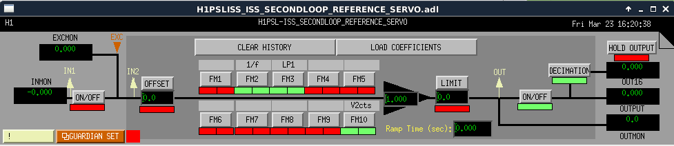
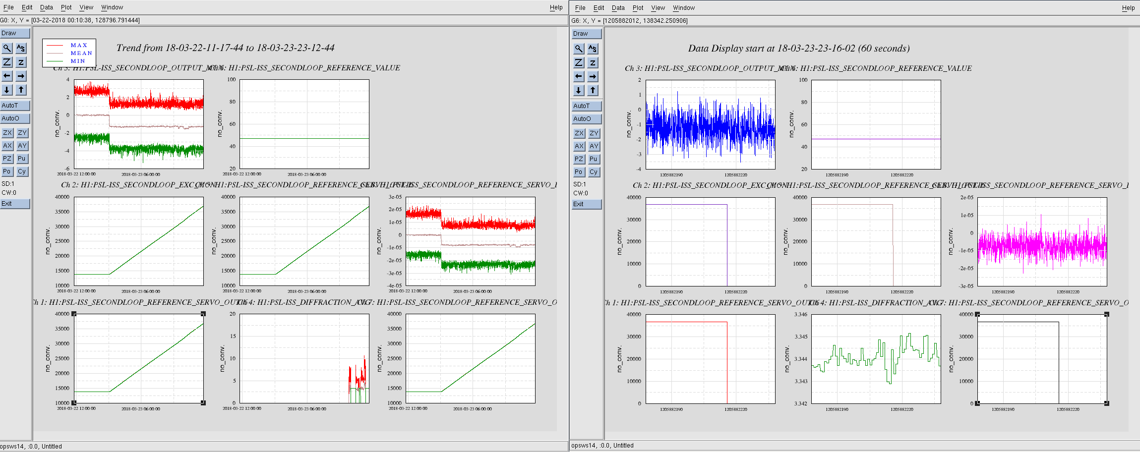
second loop reference servo input is disabled, not sure why it was enabled, not in use, but integrator started driving the signal yesterday, climbed to 40K+ the last 24 hours:
TITLE: 03/23 Day Shift: 15:00-23:00 UTC (08:00-16:00 PST), all times posted in UTC
STATE of H1: Planned Engineering
INCOMING OPERATOR: None
SHIFT SUMMARY:
LOG:
15:10 Jeff into CER
15:14 Jeff out of CER
15:16 Corey transitioning LVEA to laser safe
15:20 Karen to EY
15:28 Hugh out to LVEA - HAM6
15:29 Thomas and Patrick to mezzanine - TCS chillers
15:39 LVEA transitioned to LASER SAFE
15:41 Thomas and Patrick back
15:47 Corey out to LVEA - HAM6
15:54 Chris to MX to bring scaffolding
16:05 Hugh called from HAM6 to report that the workstation isn't functioning properly
16:19 Peter out
16:20 Terry into optics lab
16:36 M2 out to MY
16:42 Peter out to PSL
17:00 Paused LASER_PWR and IMC_LOCK nodes for Peter
17:09 Chris back and into optics lab
17:19 Chris back
18:10 Jeff headed out to EY
18:21 Peter out for lunch
18:45 Cheryl and guest out
18:52 Corey out of HAM6
19:15 Corey, Terry, Hugh, and Sheila out for lunch
19:21 Jeff B out for lunch
19:30 Sheila is transitioning to LASER Hazard
19:36 Betsy and Travis back for lunch
20:13 Jeff back to EY
20:13 Jenne and Sheila to HAM6
20:27 Betsy and Travis out to EX
20:37 M2 to MY
20:53 Fil out to LVEA by PSL racks
21:06 Jeff back
21:43 Fil out and heading to EX
22:15 Fil back
Aligned the output of the 70W power amplifier into the pre-modecleaner.  Tried locking the pre-modecleaner
but the mode matching used to make the output of the power amplifier mimic the high power oscillator was not
good enough.

    The SMA to BNC adapters for the RF summing box were replaced.  It was noticed that tightening these
eliminated the RF signal altogether.

    I have turned off both the front end laser and the power amplifier.
After yesterday's gutting of the ETMX lower QUAD to remove ETM08 and it's fibers from the suspension, today we prepped to put the new ETM13 in. Travis finished the messy work of filing off the ear horns to the appropriate lengths, and then we cleaned the PUM mass and structure thoroughly with wipes and vacuuming. We prepped the ergo arm for another optic pickup, and then opened the ETM13 transport cake tin container. Upon inspection, we saw ~6 quite large pieces of something on the optic face that was up (AR), so we decided to do a cleaning before picking it up with the ergo suction. Blowing with N2 didn't seem to budge the particulate, so we applied a pour-on First Contact sheet to now dry over over the next few hours. We'll resume installing the optic into the lower structure on Monday morning.
Travis also took the empty structure opportunity to install the NMBDs (non-magnetic blade dampers) on the UIM in this main chain structure.
The serial numbers of the NMBDs install were 005, 014.
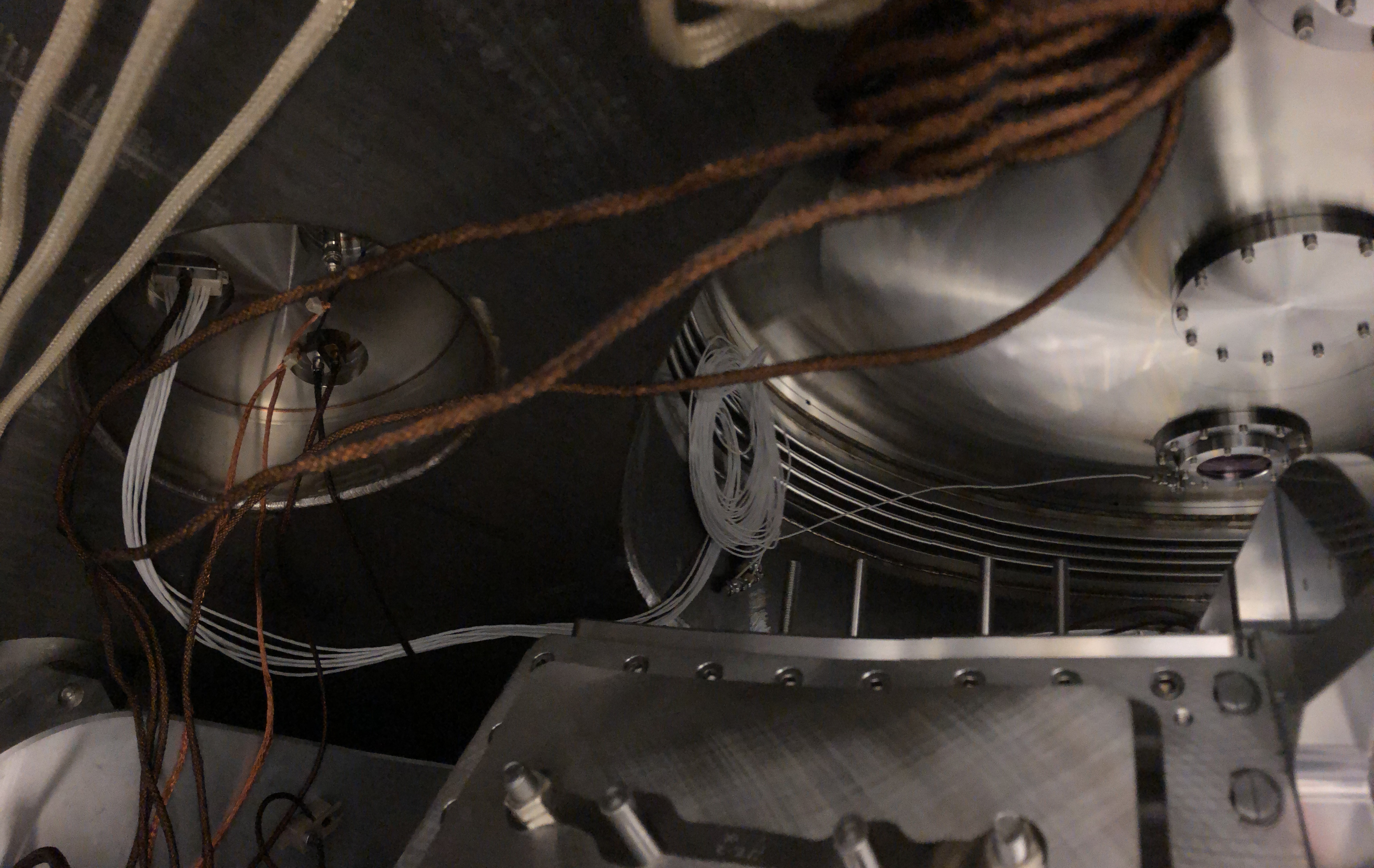
Travis and Gerardo installed the in-vac Septum flange Wilcoxon single-axis-accelerometer in Nov 2017 (it is oriented in "-Y"). This is under Ticket #4512.
There was a thought of installing additional in-vacuum accelerometers since the in-vac Wilcoxon cable can accommodate up to 8 accelerometers. At LLO one was installed on the OMC cage, but it was deemed not useful. So we opted to NOT install one on the H1 OMC. There was mention of an accelerometer on another axis on the septum would be useful, but since we are under vacuum on the other side of HAM6, that is not possible (& not sure if the clamps can accommodate this).
At any rate, I went ahead and connected the cable to the in-vac side of the D-Flange (specifically: Connector D1 3C2). This cable does not contact the ISI at all; it is in fact, spooled up in the "nozzle" at the Septum.
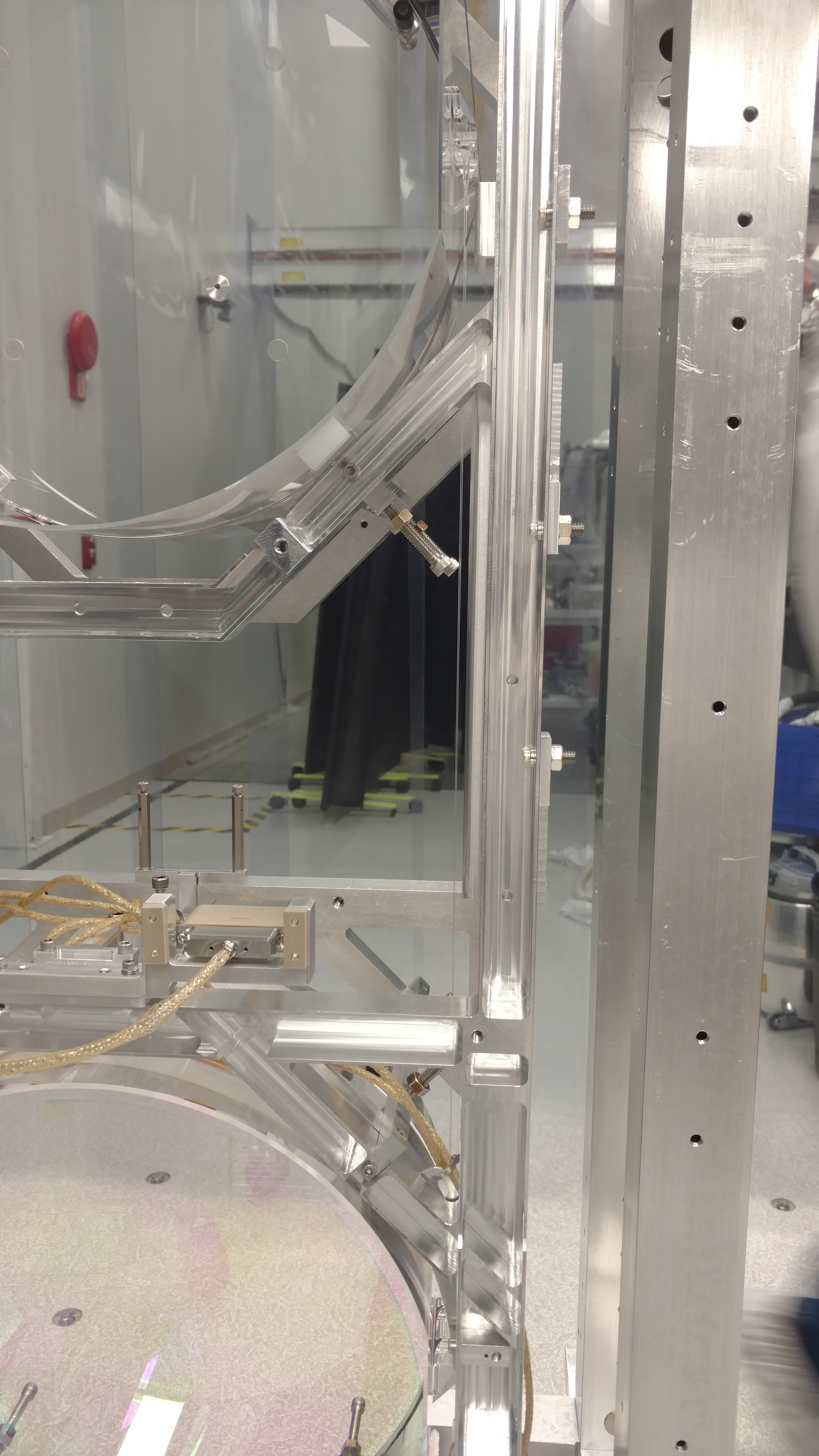
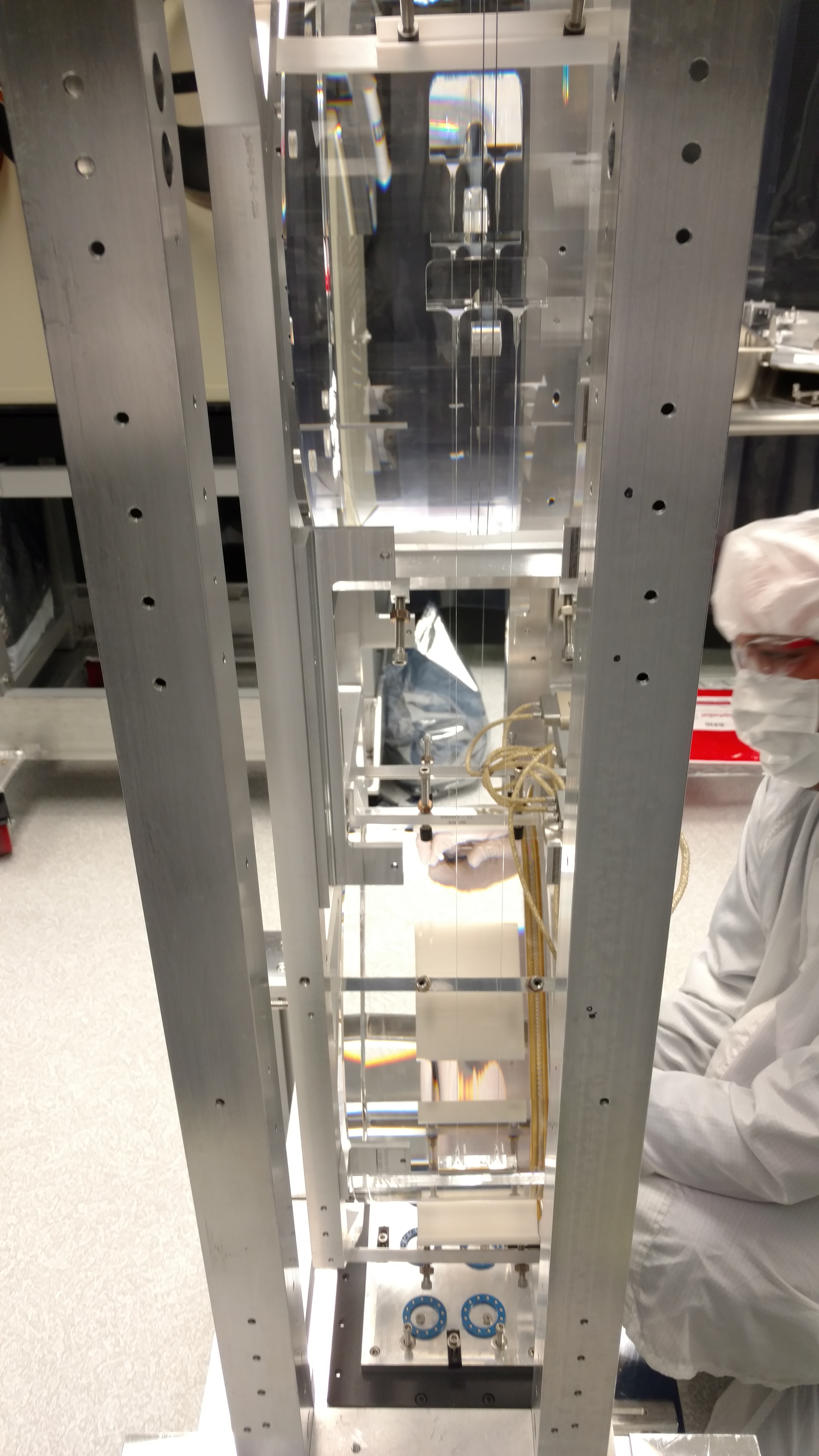
Photos are attached (the first one is a panoramic [hence no thumbnail preview] showing from flange to flange.)
There is no in-air cable attached. Richard says they can connect something up whenever someone wants to use this accelerometer for testing.
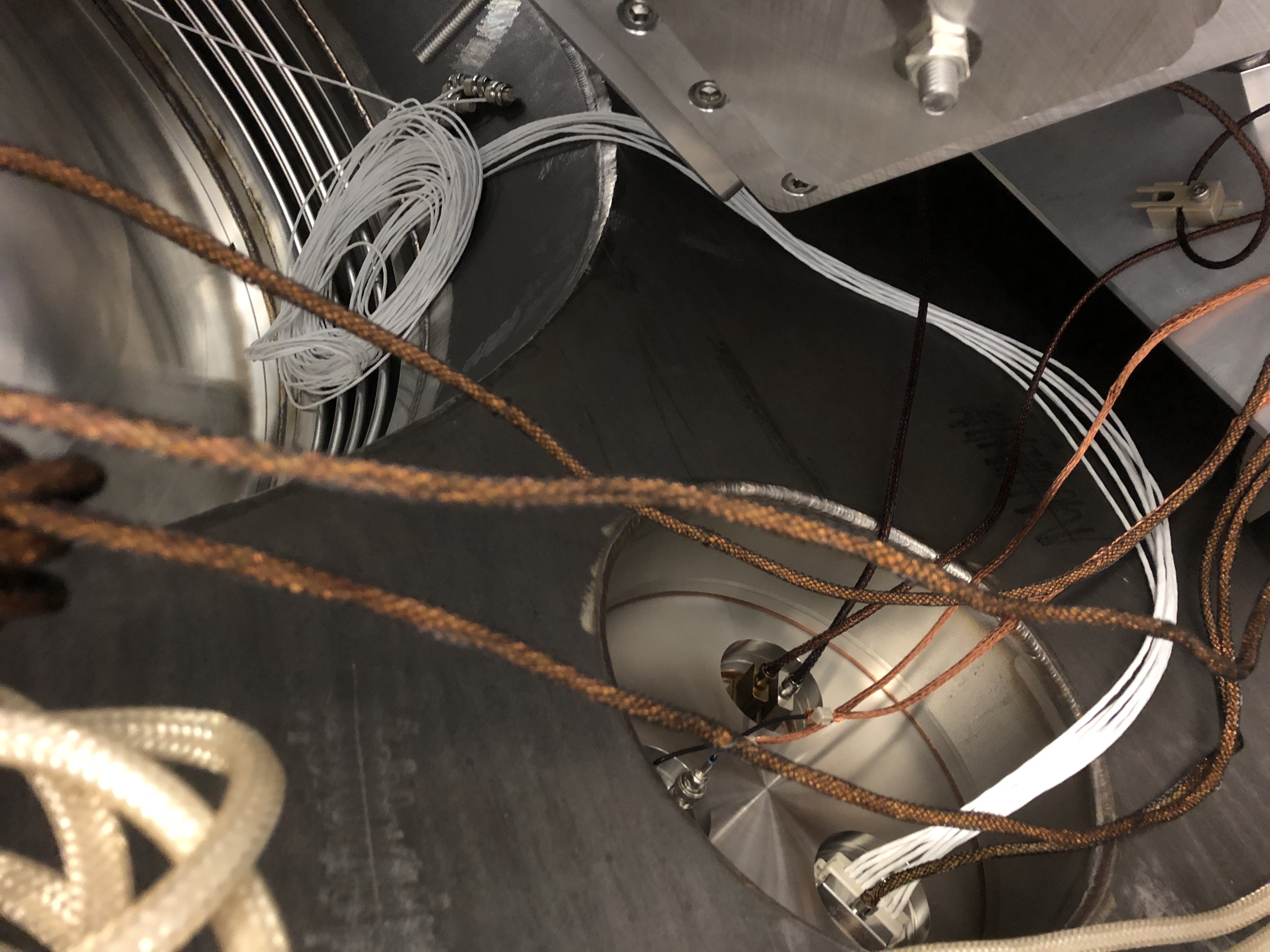
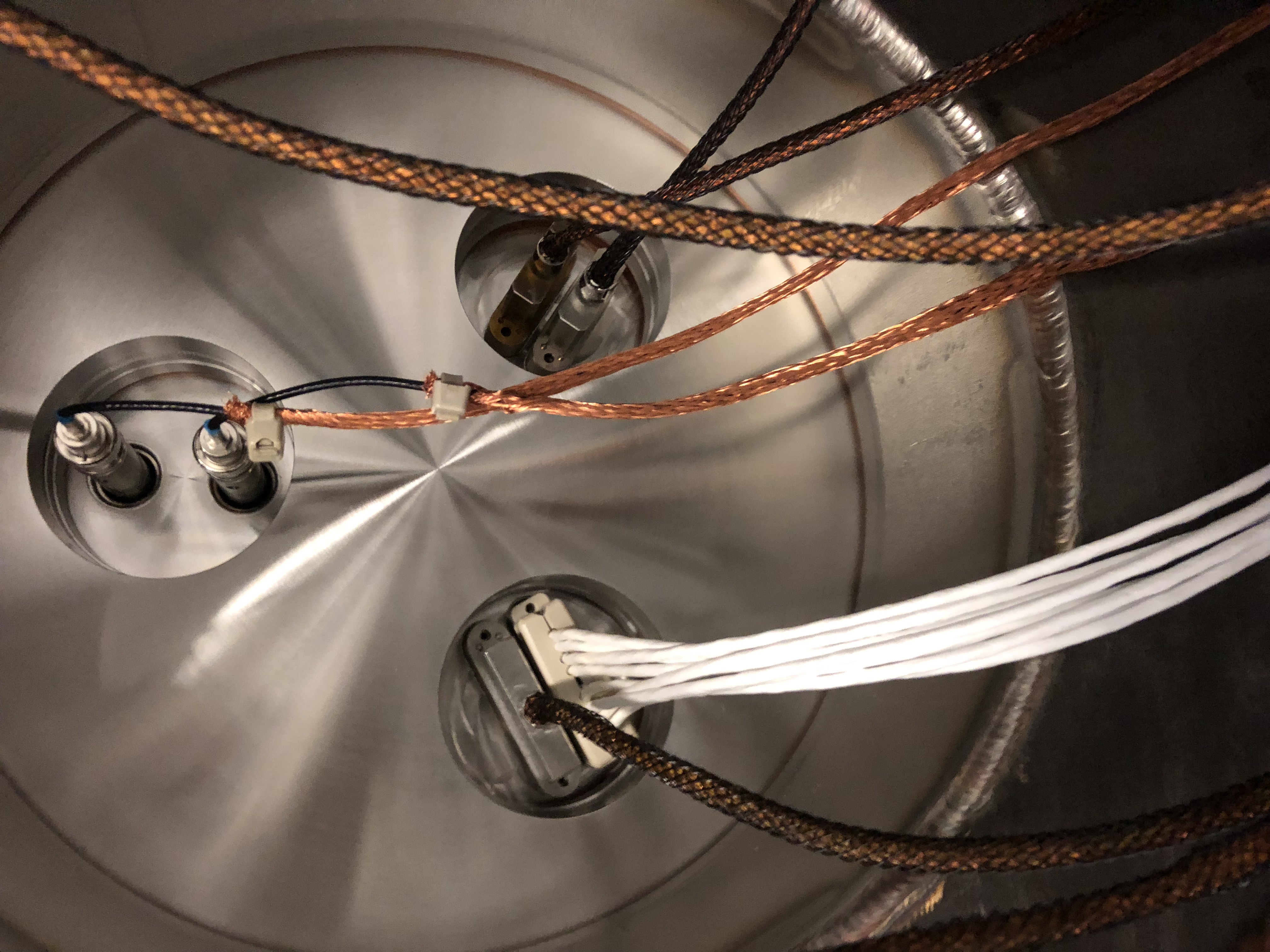
To help prevent this spool of cable from slipping off the nozzle down to the bottom of the chamber, Hugh thought it a good idea to put a tie-wrap on the spool to help it stay put. Here's his alog of this.
   WP #7439 - Jeff B. & Dave B.

   All dust monitors, except End-Y and the Optics Lab are running at a 19200 baud rate. To synchronize the network port speeds across all dust monitors, today upped the End-Y dust monitor network port speed from 9600 to 19200. Reset the dust monitors for the new speeds and booted the Comtrol. Power cycled the weather station. Dave restarted the weather station (aLOG 41124).

   At next opportune time will do the same for the dust monitors in the Optics Lab. This will have all networked dust monitors running at the same speed.
    Removed the remains of the house vacuum system from End-Y. The PCV piping and cabling are gone to recycling. Will address the mid stations, End-X, and corner station as access opportunities permit.

  WP #7440
Reinstalled the dust monitor VEA-2 at End-Y to cover the door removal next week. As before, it is located inside the BSC cleanroom and the alarms are set for Clean-100.
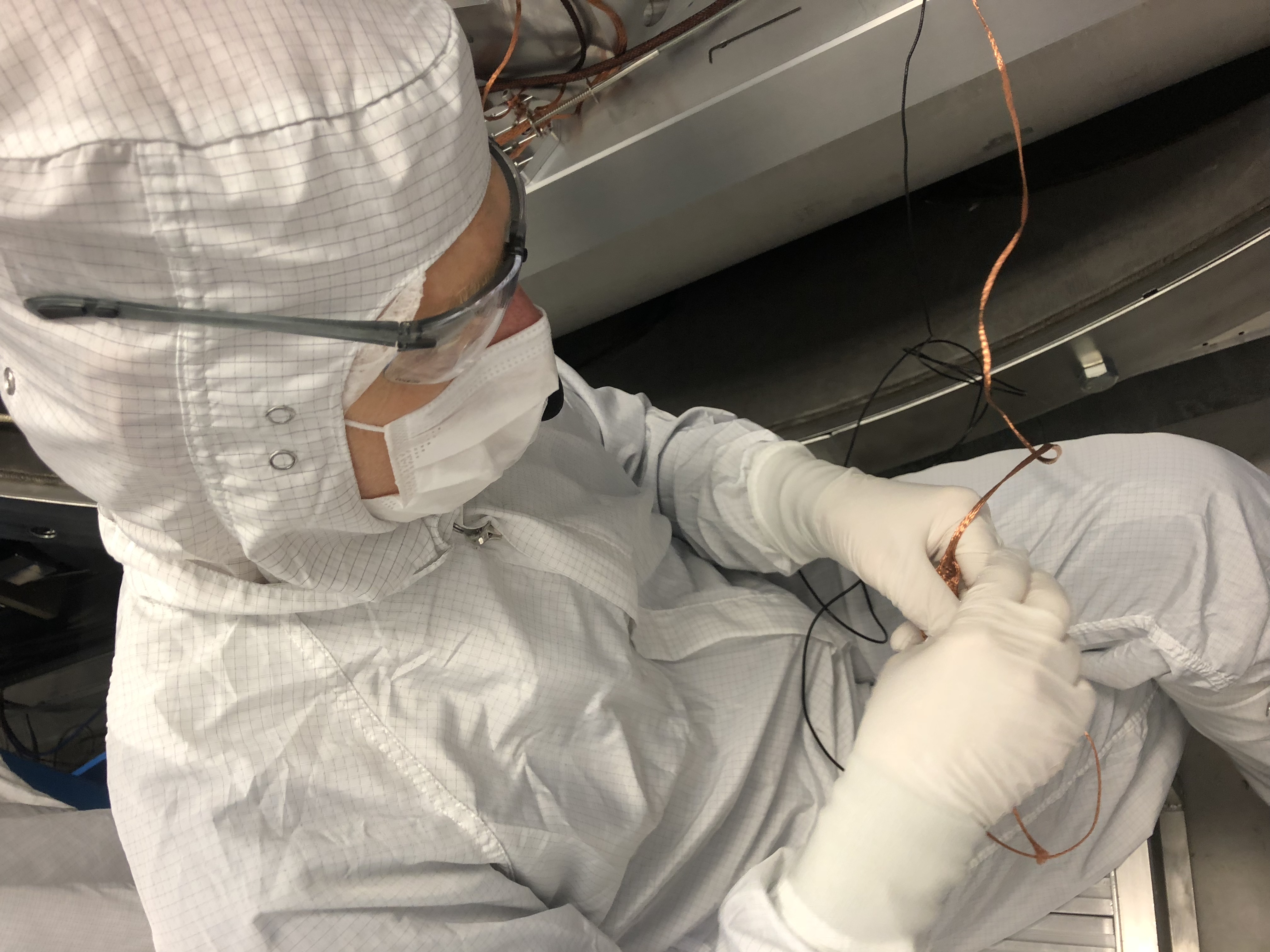
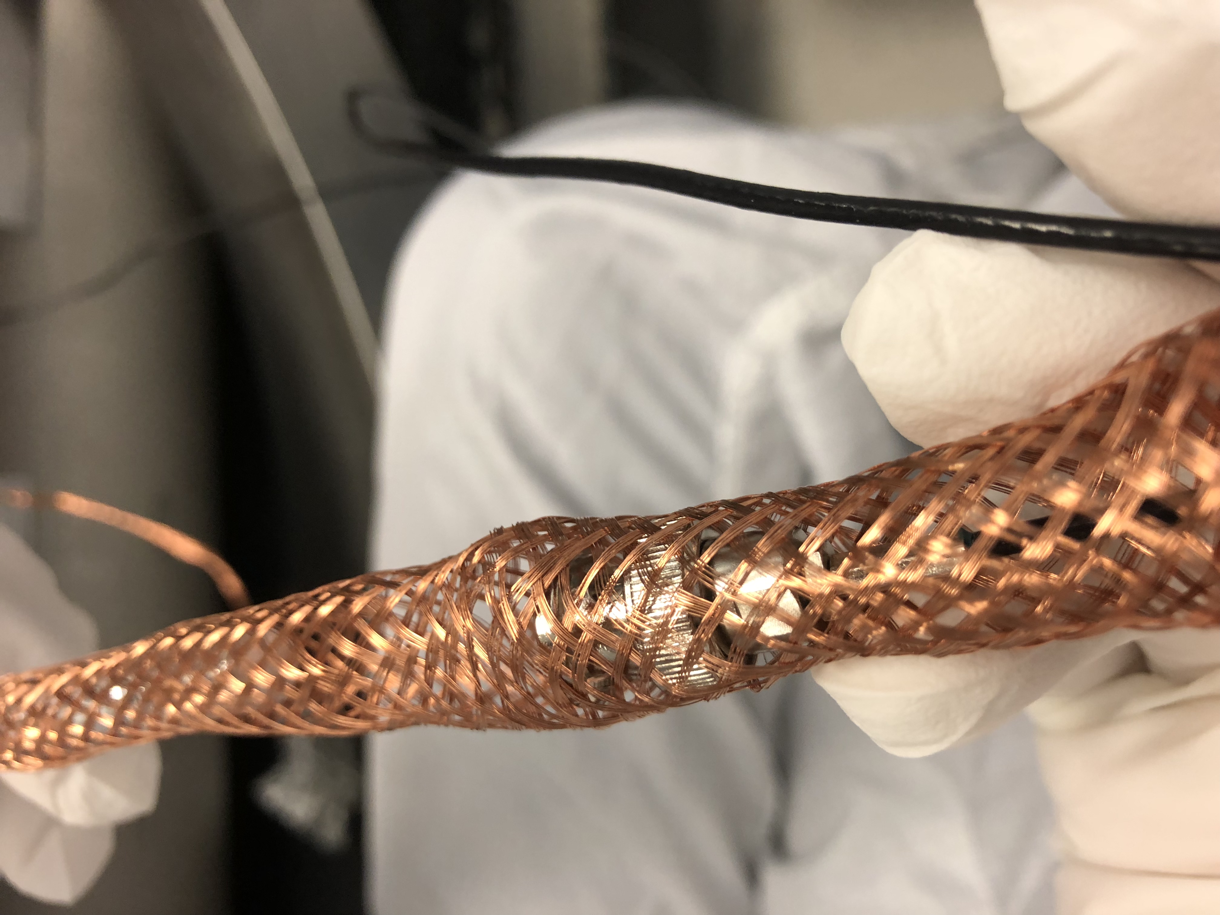
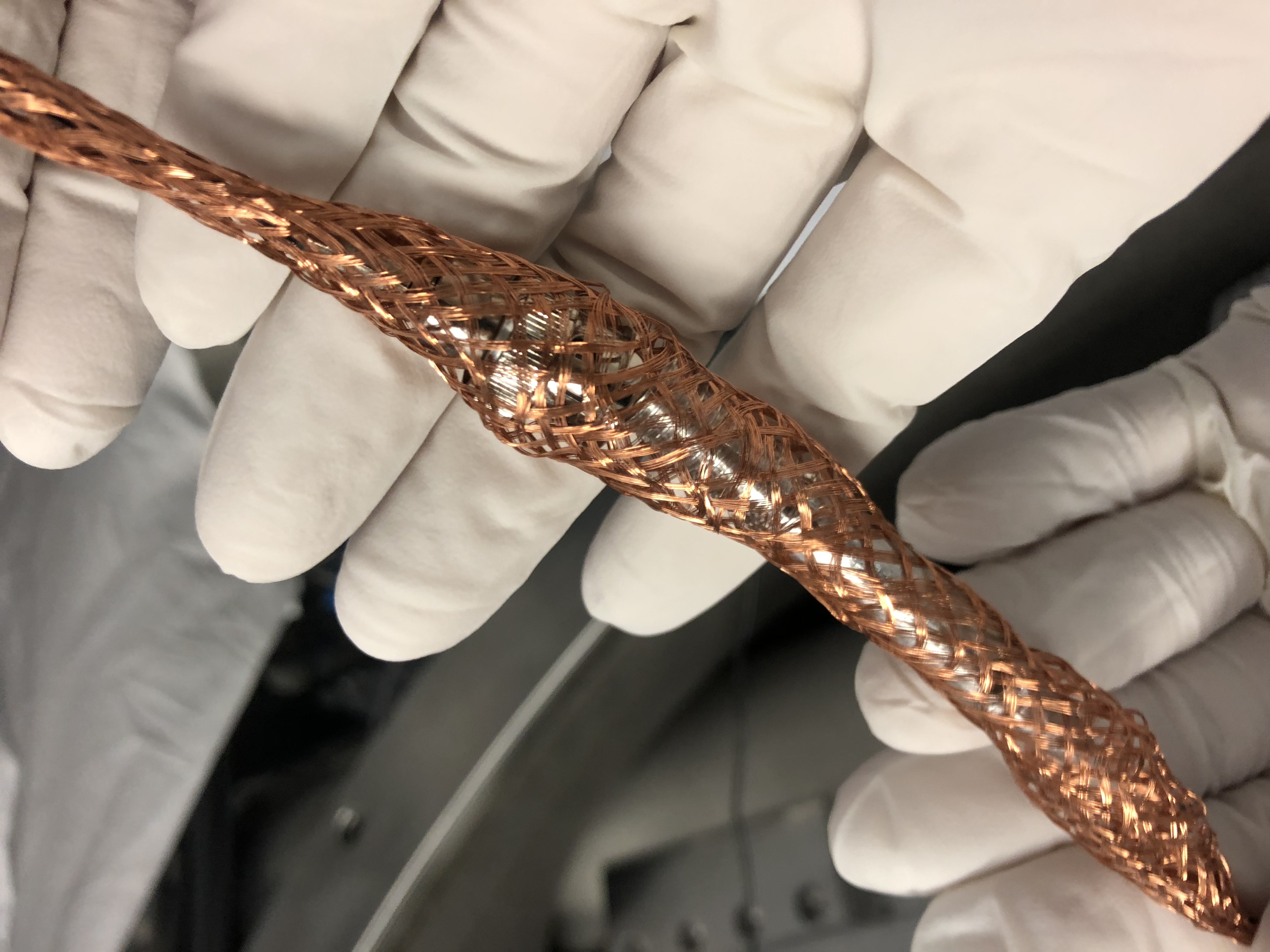
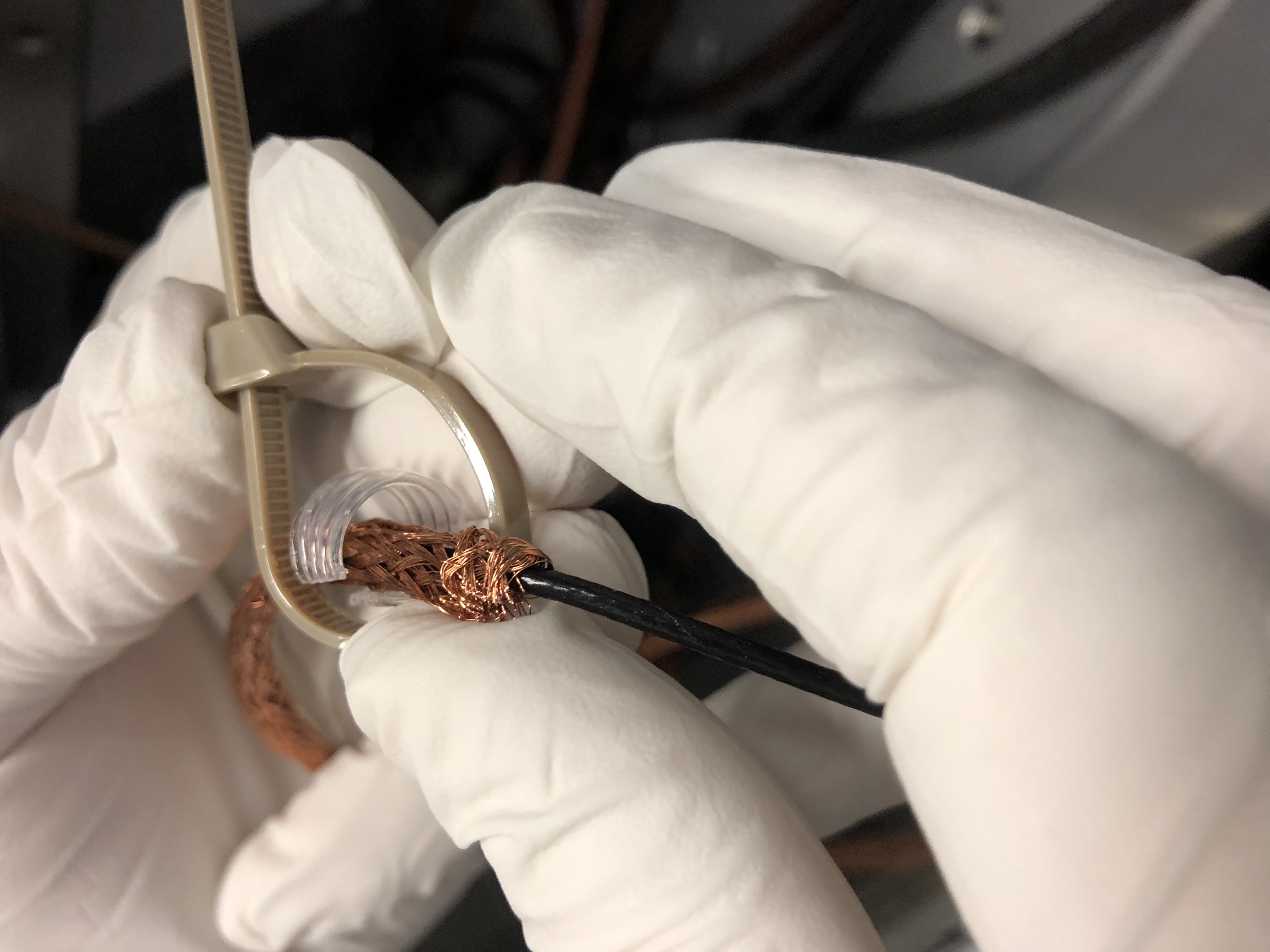
Corey & I managed to milk the new V3 sensor cable through a new length of copper braided shield. We had a 'fid' to help but more than two hands was a big factor as well. We (I) was unable to get the too large a zip tie snug enough around the cable to hold the braid in position but only at the sensor end. At the BNC connector end back at the feed thru, we could get all our hands in play and that one is secure. I have smaller peek zip ties coming from Accu-Glass arriving next week and if they can be ClassA'd in time, we'll use those. Otherwise we'll have to take the sensor off the platform and snug the tie as we did at the other end with more hands. I was worried about damaging the cable at the sensor where we can't get enough hands into play to make sure nothing but the zip tie gets reefed on. The big zip ties just require too much force to close tight enough.
We (I) still need to change the conflat gasket back at the feed thru, as well as the above mentioned cable tie job--next week.
And of course good spectra and any balancing if SQZ crew changes the payload.
We left the ISI locked.
Old Corner 3 Vertical CPS sensor SN 12023; new SN 12015.
Addendum: Since we had already reset the V3 sensor gap, we decided to re-gap what needed it. The H3 CPS was over 6000 counts and that was the hardest one to access, The other two horizontal sensors were over 1000 counts so we did those too. For the verticals, we redid V1 which was over 1300cts.
We then did an unlock/relock test and saw that the local verticals shift 200 or less counts whereas the horizontals shifted between 1600 to 2200 counts. Have to move the lockers to fix that. Naturally, in the cartesian basis, X Y & RZ have the largest shifts, namely 35000, 75000, & 16000 nanos while Z RX and RY shifted just 3600, 1400, & 5800 nanos. Resetting the sensors of course require resetting the Isolation Targets--done.
Addendum II: I will put actual redlines on D1201388 but just to put it here in case anyone thinks of a problem, we ended up with 110kg more counter weight than the plan expected by SYS--that's an awful lot of mass the plan was missing.
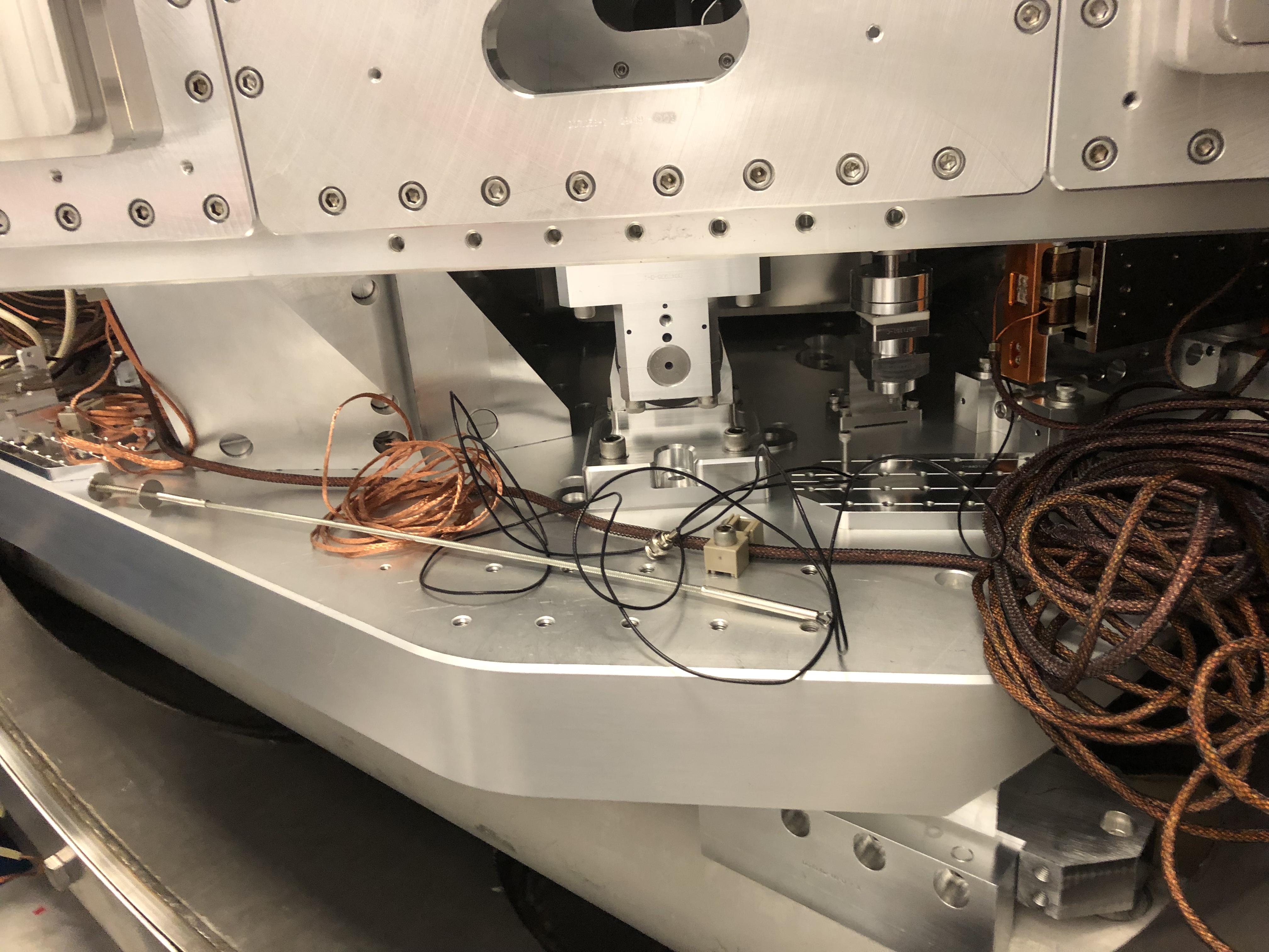
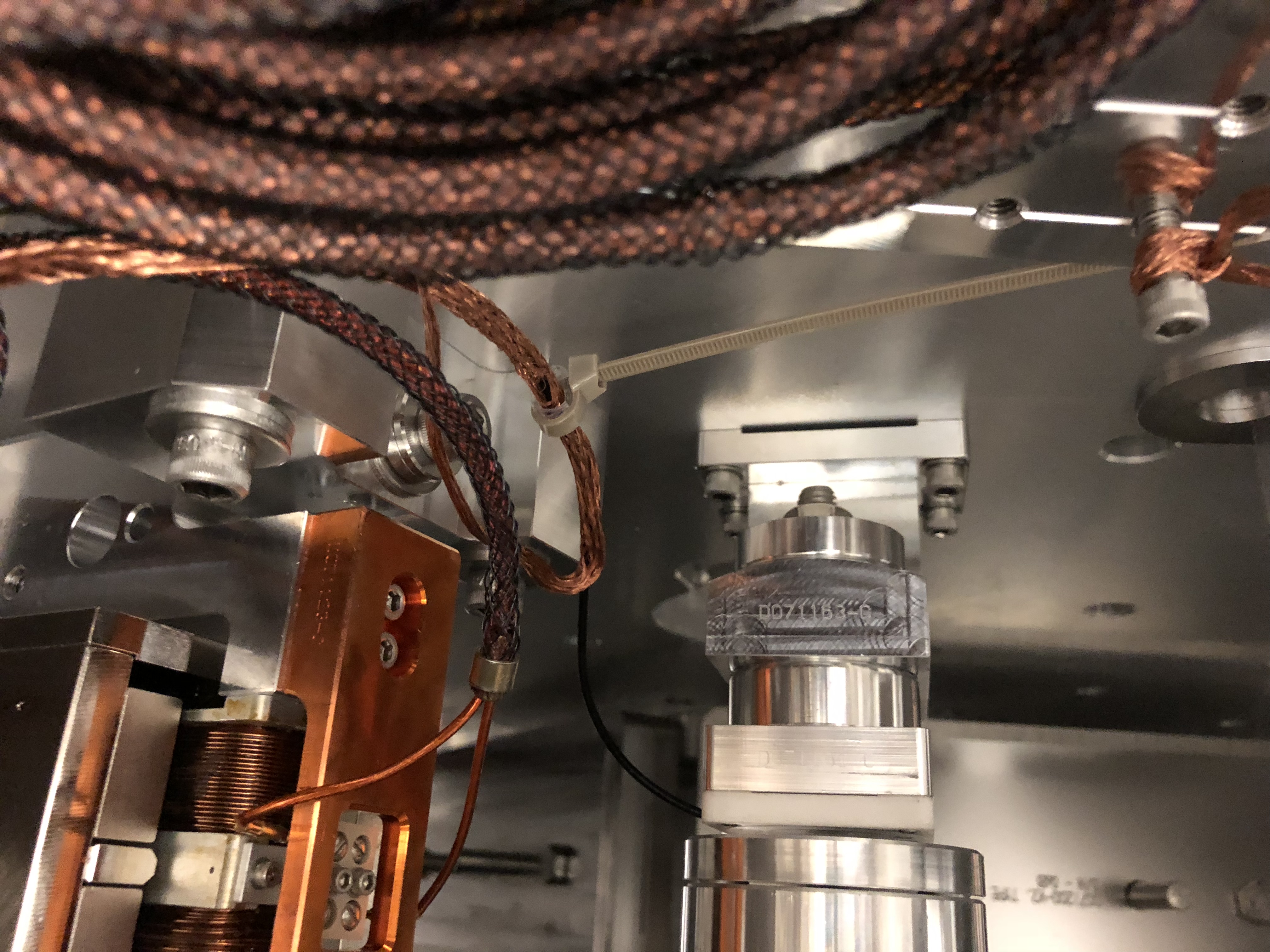
Attached are some photos from today's CPS "vascular surgery" work. The photo names summarize what's going on.
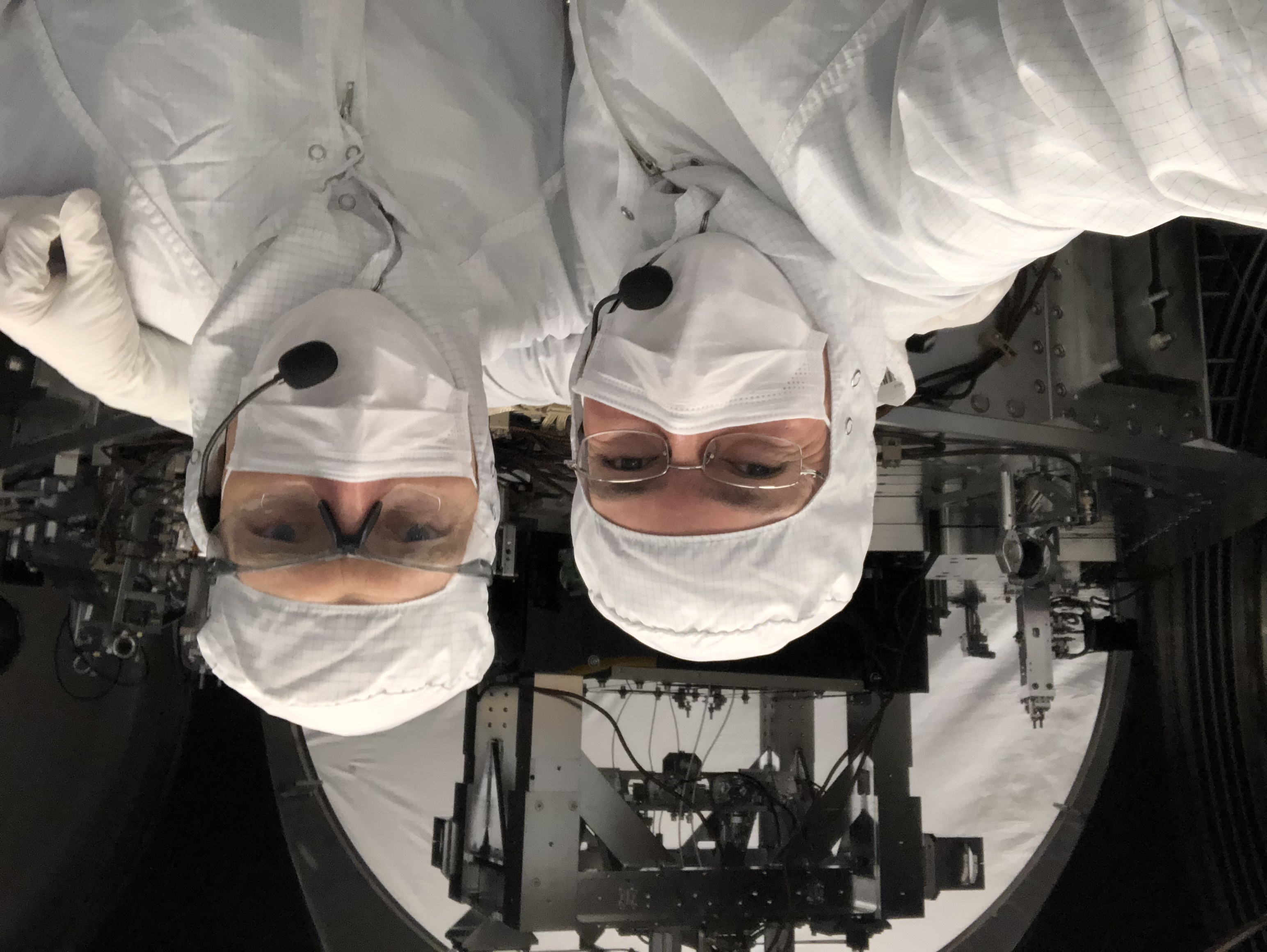
(Also attaching a selfie of Hugh & myself after today's work. March & April are respectively our 20-Years-With-LIGO-Anniversaries. Fitting that we got to do some SEI work together this last week. LIGO Seismic Bros for Life!) 🤓 [thumbnail is upside down, but full image is good.]
Terry, Sheila, Arijit, TJ,
Today we made one more attempt to get the beam from the OPO aligned into HAM5 and out to HAM6, but we haven't found the beam.
Keita loaned us a Nikon D7100 which was much better for getting a clear picture of what we were looking at than the viewer we were using yesterday. Photos will be attached to this alog latter.
FIl also cabled the HAM5 illuminator up to the new beckhoff controls, so we could turn that on and off.
We started out by manually aligning the beam again through the apertures, doing a little bit more careful job this time by using the viewer to identify the edges of teh aperature and center the beam half way. We can still see the beam hitting ZM2 through the HAM5 viewport. We were also able to sometimes see the beam coming out the HAM5 viewport (perhaps going under the fly-offf mirror on the OFI), but latter this afternoon we weren't able to repeat that. We were never able to see a beam in HAM6.
We are leaving the OPO locked and generating a beam (we again have two soft door covers with a small gap to let the beam out). We have ZM1+ZM2 scanning with an amplitude of 10,000 counts for both pitch and yaw, and SRM scanning 1000 urad.
If this does not work, we may wait for a beam from the PSL to become available and try to see the rejected scatter from the OFI polarizer in the path towards the squeezer.
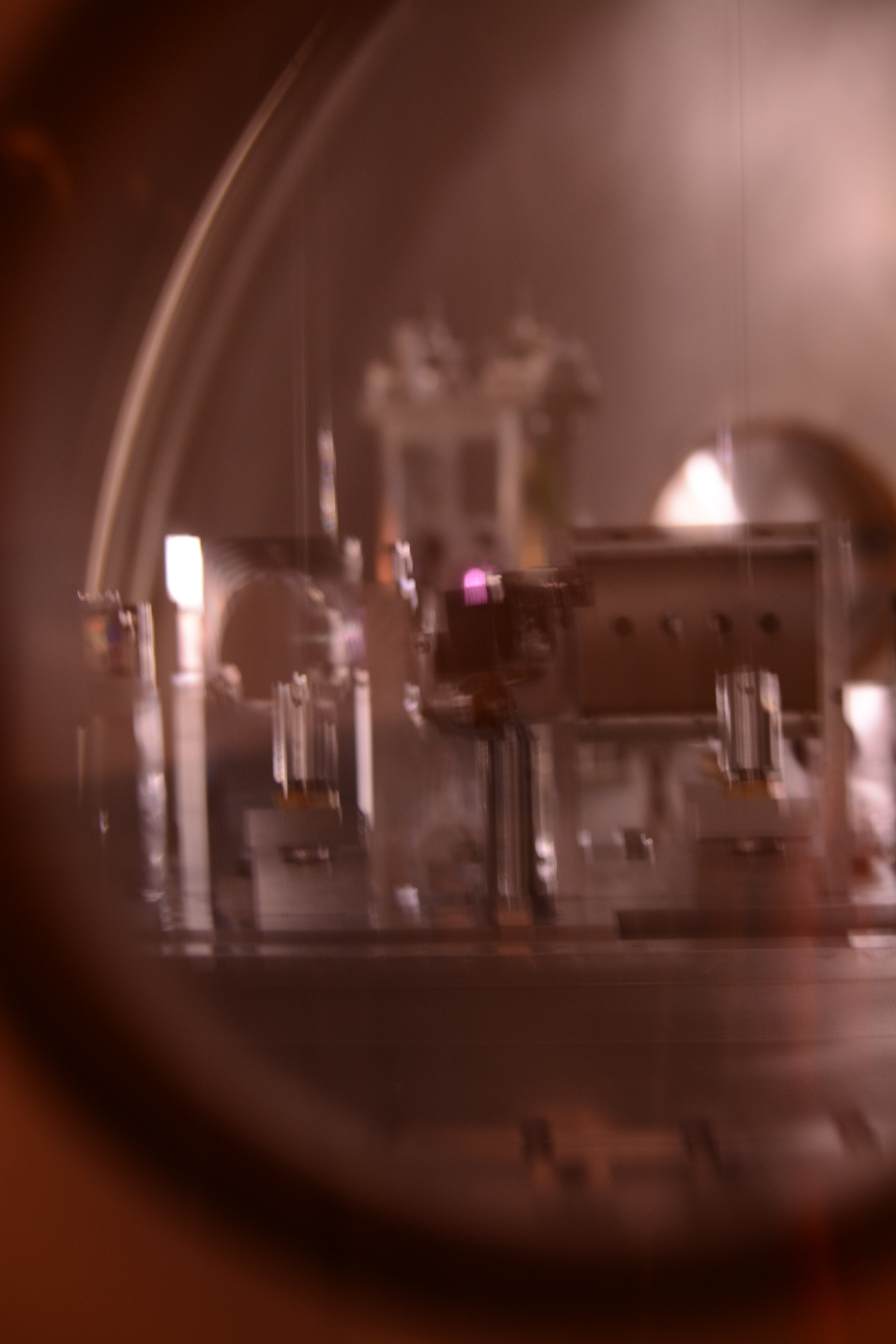
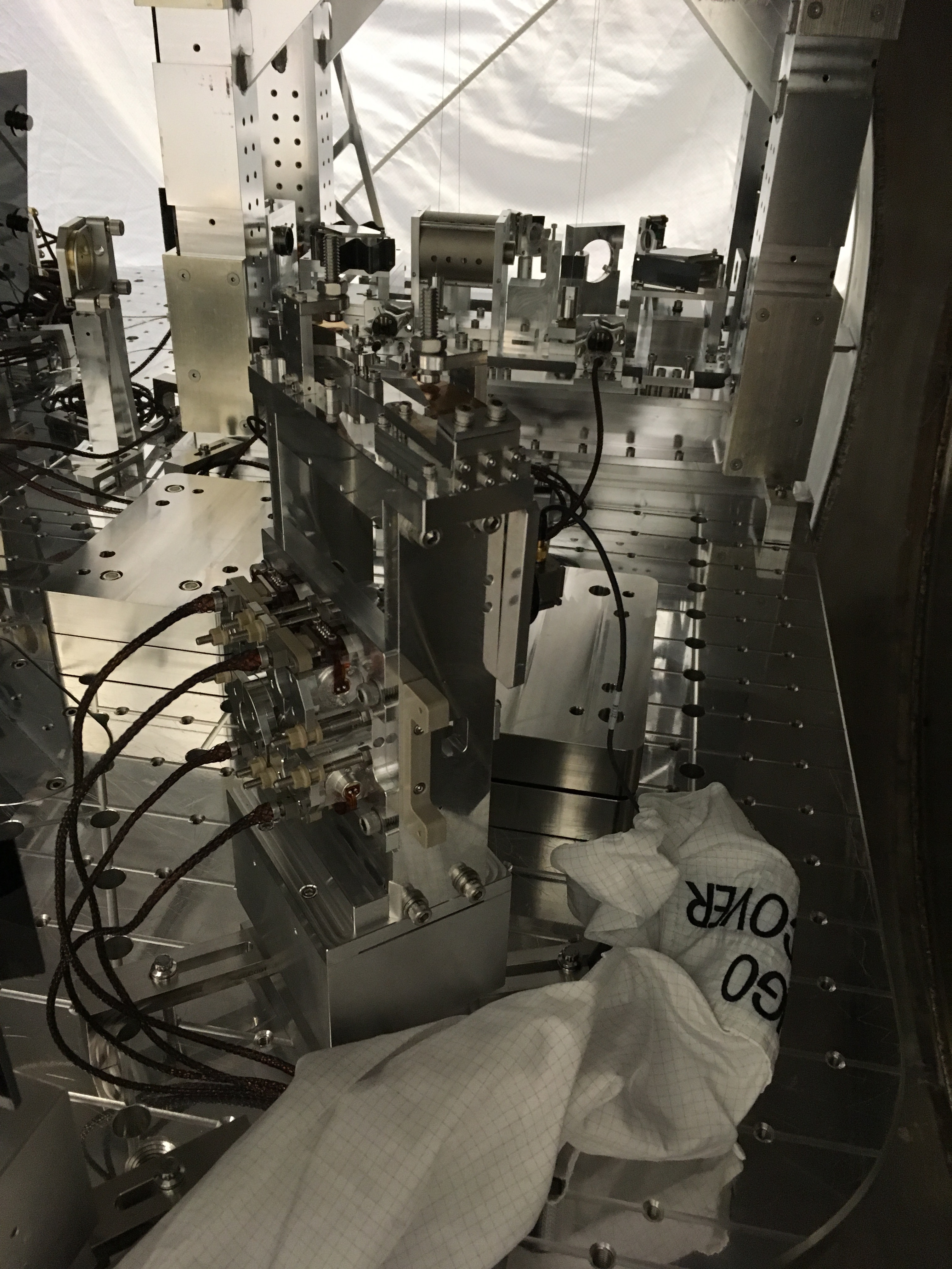
Here are some images to help clarify what we saw.
I can't find an up to date drawing of the HAM5 layout, but here is a preliminary drawing https://dcc.ligo.org/DocDB/0121/D1500303/002/HAM5.PNG, which shows ZM2 much further in the +y direction than it really is placed. In reality the beam from the OFI to ZM2 runs nearly parallel to the septum.
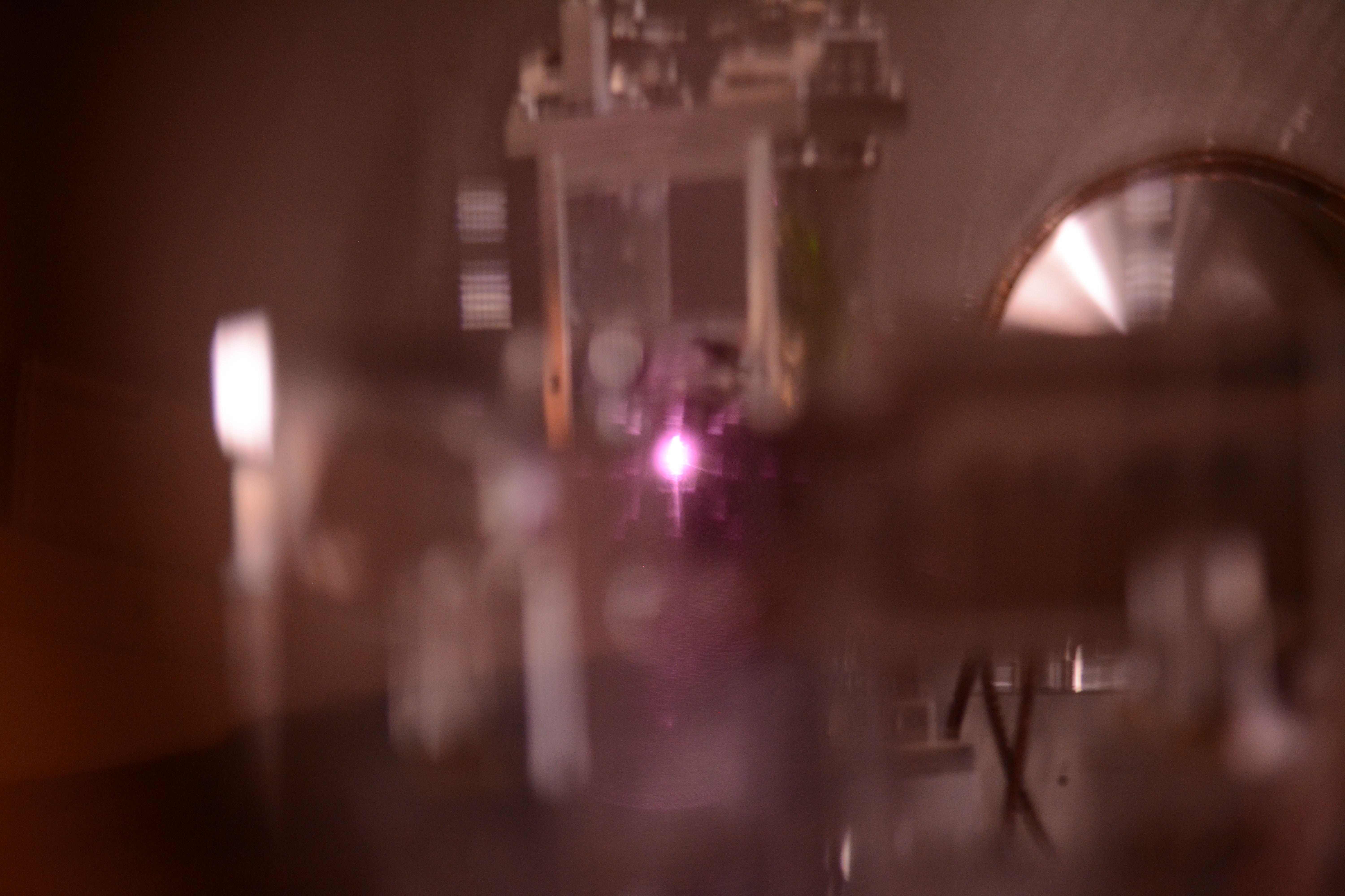
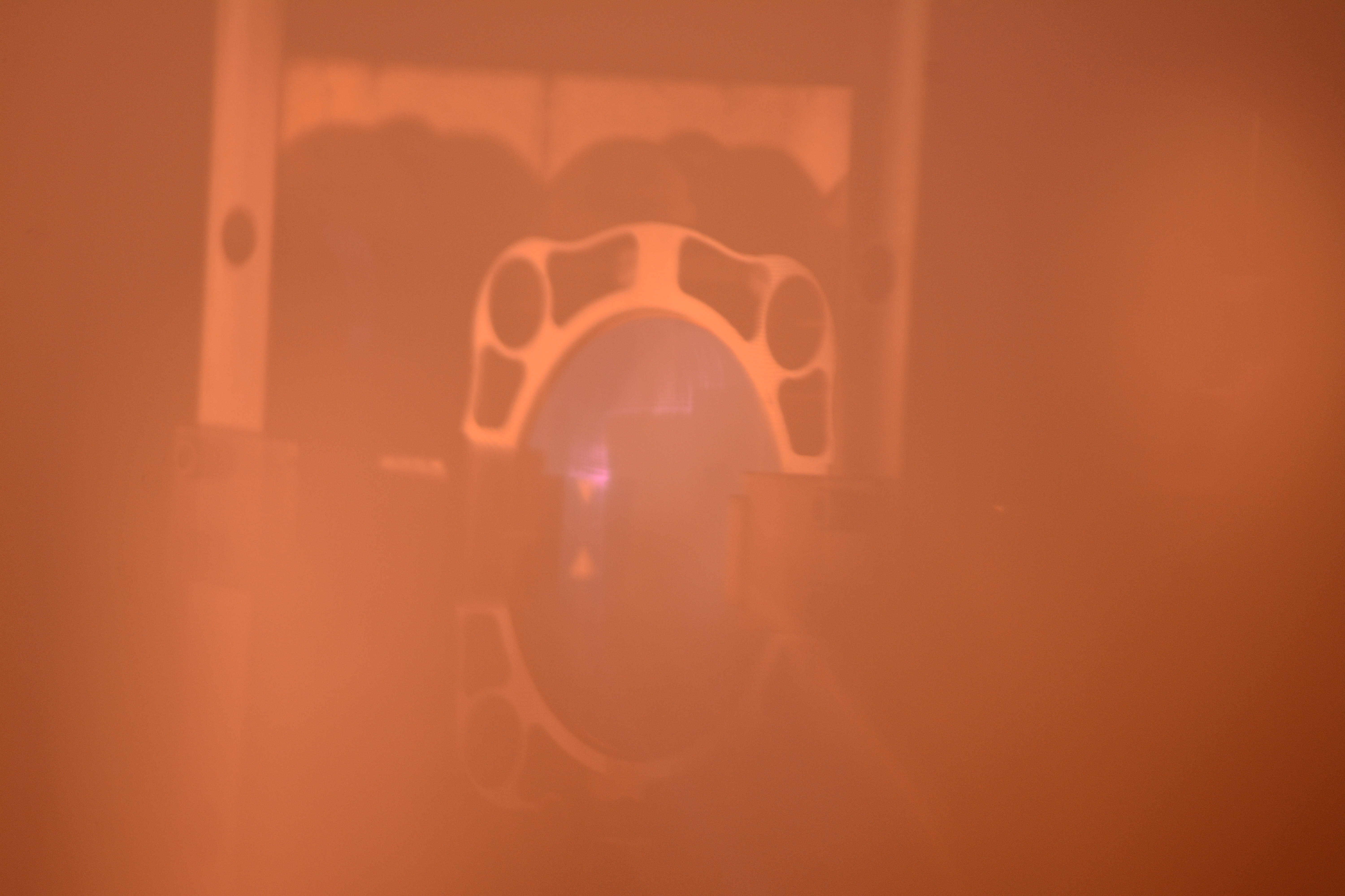
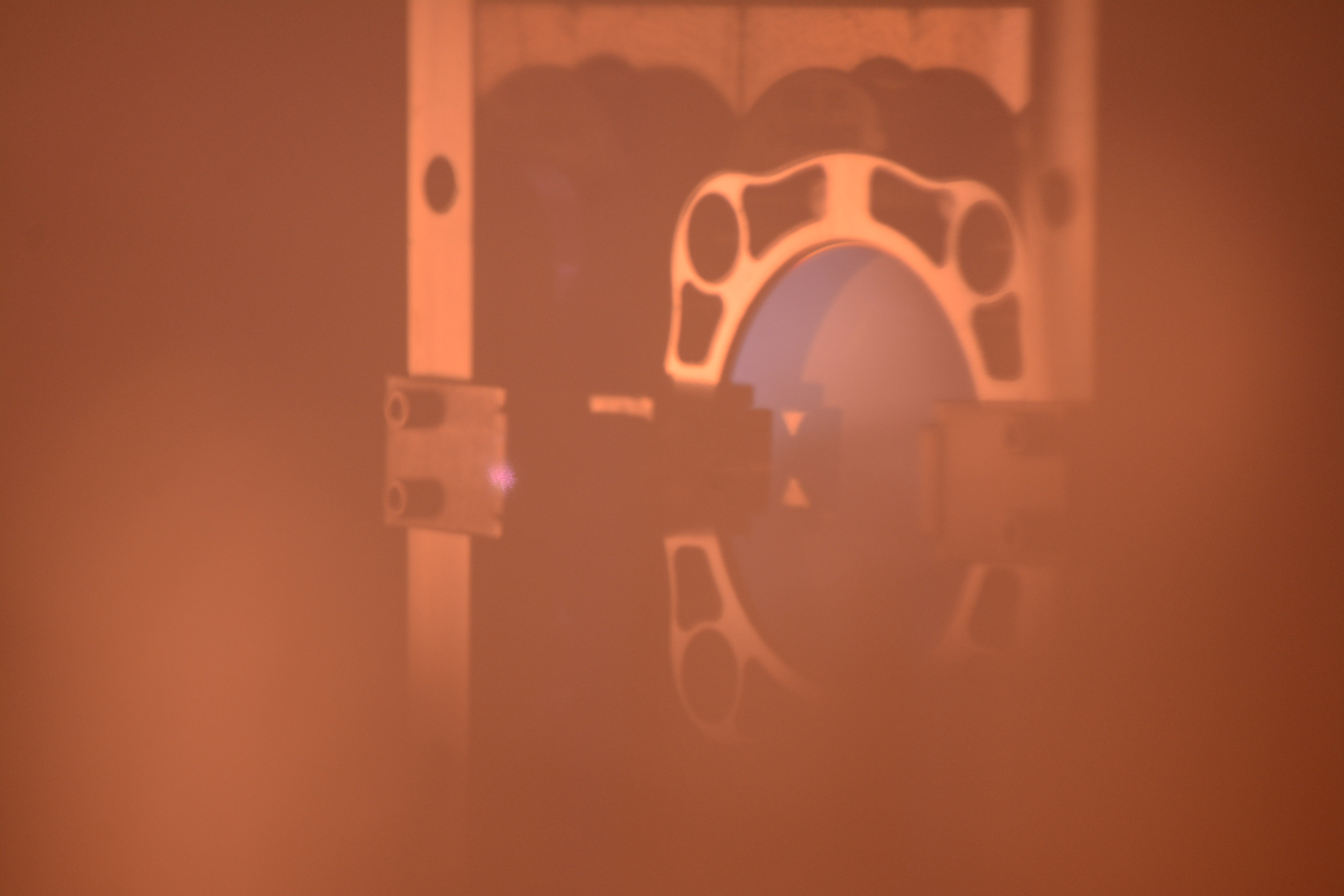
Here are some photos taken from the easternmost viewport on the north side of HAM 5 (the -y viewport on the +x side of HAM5). The first photo is a blurry overview of what we can see, the fly off mirror for the squeezed beam is in the center (there is a black glass clip on the back of the mirror), behind that you can see the cage of ZM2. The violet looking thing that is just peaking over the black glass clip is our beam or scatter from our beam.
The second photo shows that at some alignments on ZM1/ZM2, we can see a quite bright thing in HAM5 which is probably our beam. The fourth photo shows an alignment for ZM1 for which the beam clips on the bracket for the eddy current damper on ZM2, while the third photo shows an alignment of ZM1 where we think the beam should be hitting ZM2. You can see some difuse IR light, and what looks like the outline of the black glass clip in that scattered light. This seems like a good candidate for our best alignment, you might think that this scatter means that the beam is hitting or nearly hitting the fly off mirror with the black glass clip, however, we saw nothing in HAM6 for this alignment.
A few images and notes to help
1) Photo of path from ZM2 to OFI bench, from LHO alog 39663 and "big picture 1" see links below.
https://alog.ligo-wa.caltech.edu/aLOG/index.php?callRep=39663
https://alog.ligo-wa.caltech.edu/aLOG/uploads/39663_20171206192338_ZM2_BigPicture_1.jpg
2) LIGO-D1500303 linked above is / was a temp (preliminary) layout. Refer now to SYS links below. We have added a note to D1500303.
a) LLO
LHAM5 - LIGO-D0900456
ZM2 - LIGO-D1600094
b) LHO
WHAM5- LIGO-D0901129 (please note this top level is pending, refer to D1700472 and D0900456 for now)
ZM2 - LIGO-D1700472
Hope these help. Corey A, Eddie and Calum
It is with a somewhat heavy heart that I cut the fibers out of the final Hanford ETM to detect the first gravitational waves ever. We removed the ETMx from the lower structure and stowed it in its cake tin. The new ETMx will be installed tomorrow in prep for a fresh weld next week.
Shown below, ETM08 with it's un-guarded set of fibers, about to be removed.
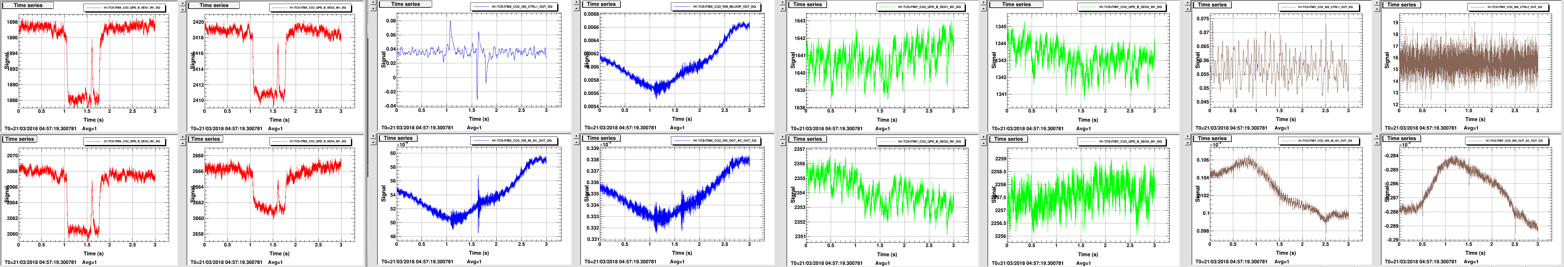
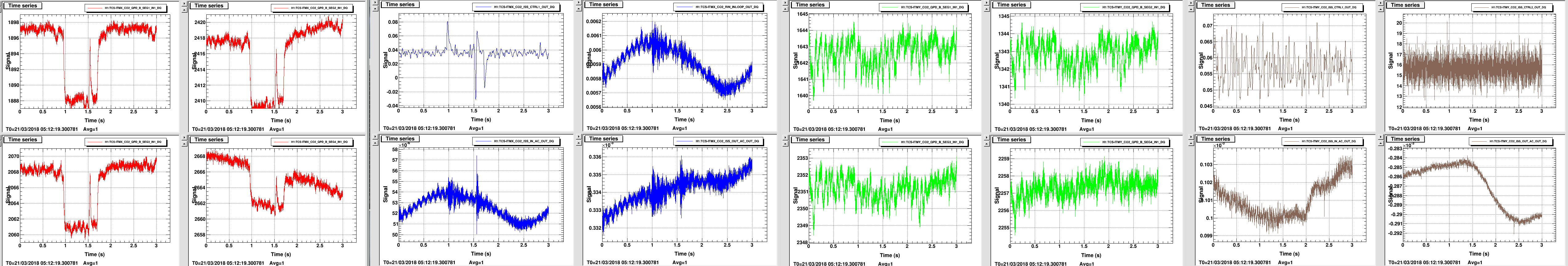
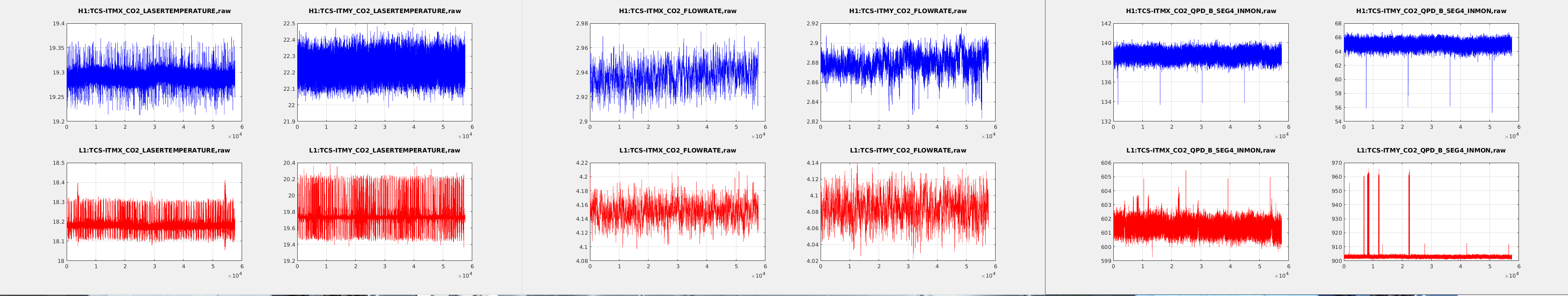
I've looked at 3 consecutive glitches in TCSX QPD B using the _DQ channels added yesterday. The shape of all 3 glitches are the same, and have a shape that looks very much like a step function (with a second glitch about 3/4 of the way through the first). To the best that I can measure in dtt, the interval between the first and second glitch is 900.098 seconds, and between the second and third glitch is 900.577 seconds, so 15 minutes +/-0.5 seconds. Attached plots of the three glitches show that the ISS and RIN signals also see the glitch. Related alog 41076.
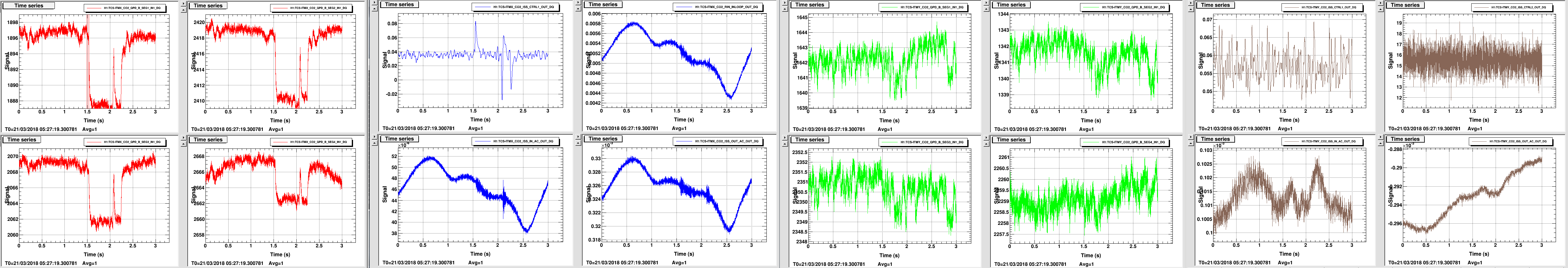
plot showing one hour of data, showing the qpds in H1 and L1 glitch every 15 minutes:
Update on what I did with ZM1 today.
Summary: the UL flag now looks much better, but I dropped a screw down into the ISI and I topped out some adjustment screws.
After talking with Jeff K this week about what might be going on, I remembered that the UL OSEM flag was slightly askew from the other flags. Jeff's data may also point to a problem coming from that area so I wanted to see if I could straighten or align the flag today. I pulled the flag and rolled it on the table and you could see that the tip of the flag was not straight. I replaced it with another that I had brought with me and it looked slightly better, but still not great. Roll tested this one as well and all looked good, hmm. So I put it back in and then tried to move the OSEM in the desired direction with some success. All the flags now seemed to sit a bit lower, so I adjusted the height but I found that the screw to lock down this adjustment couldn't reach anymore. I'll have to get some longer ones tomorrow. Overall, the UL flag is now much more centered and the others are good as well.
As I was putting the earthquake stops back on I fumbled one of the 4-40 screws and dropped it right down into one of the through holes on the table (I blame the gloves). I could not see a way to get to it without removing one of the HAM side panels, so I will consult with SEI team and take action tomorrow.
After talking with Hugh and Jim it seems that we might leave this screw where it is unless it starts to cause some issues.
As a future reminder, I dropped a 4-40x.5" SHCS over the South corner of HAM6. It fell through one of the helicoiled through holes and dropped inside the table. The hole it fell through is above spring post #1, I am told. I did not see or hear it fall through to stage 0, and I could not locate it through the holes in the wall panels on the South-East side of the table. During their CPS investigation, Hugh and Corey had one of the access panels removed on that corner, but I also did not see or feel anything.

