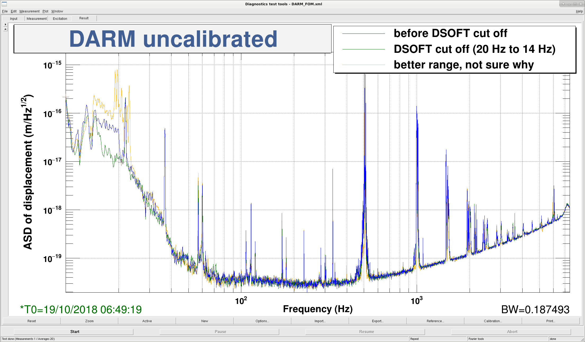
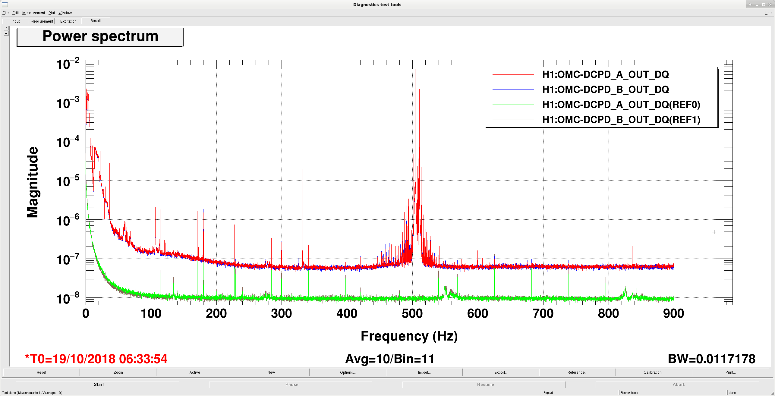
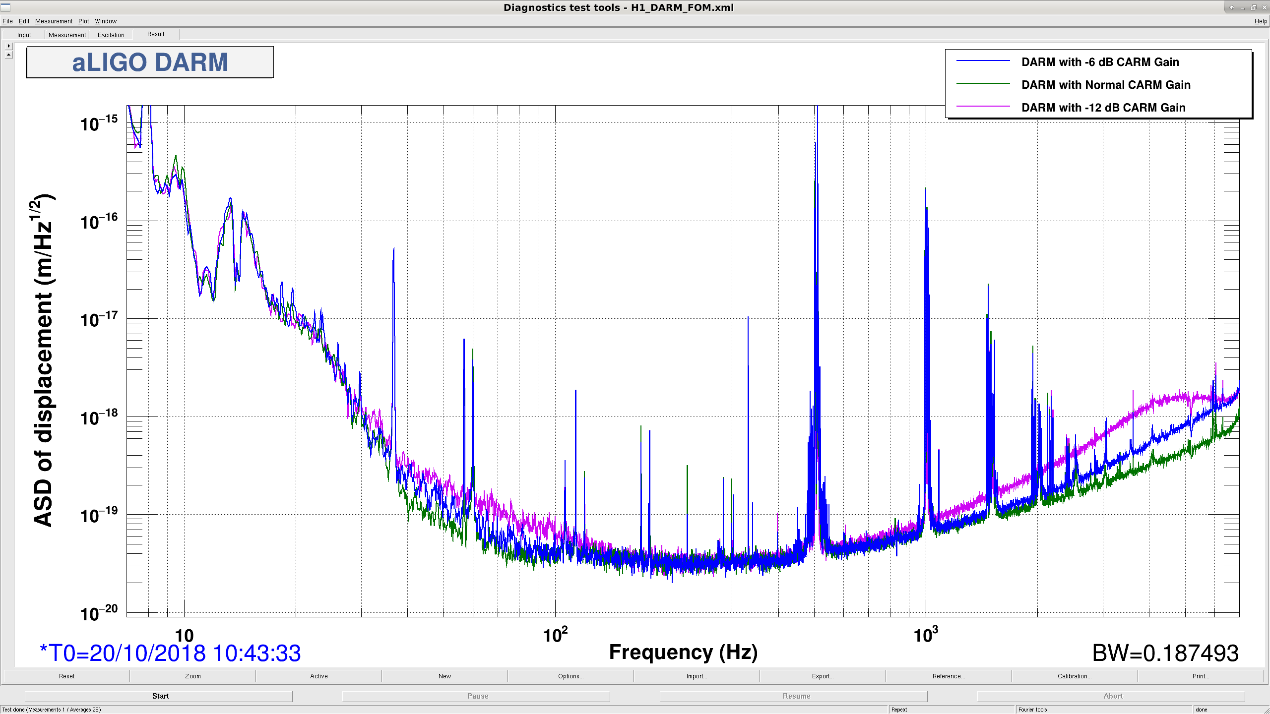
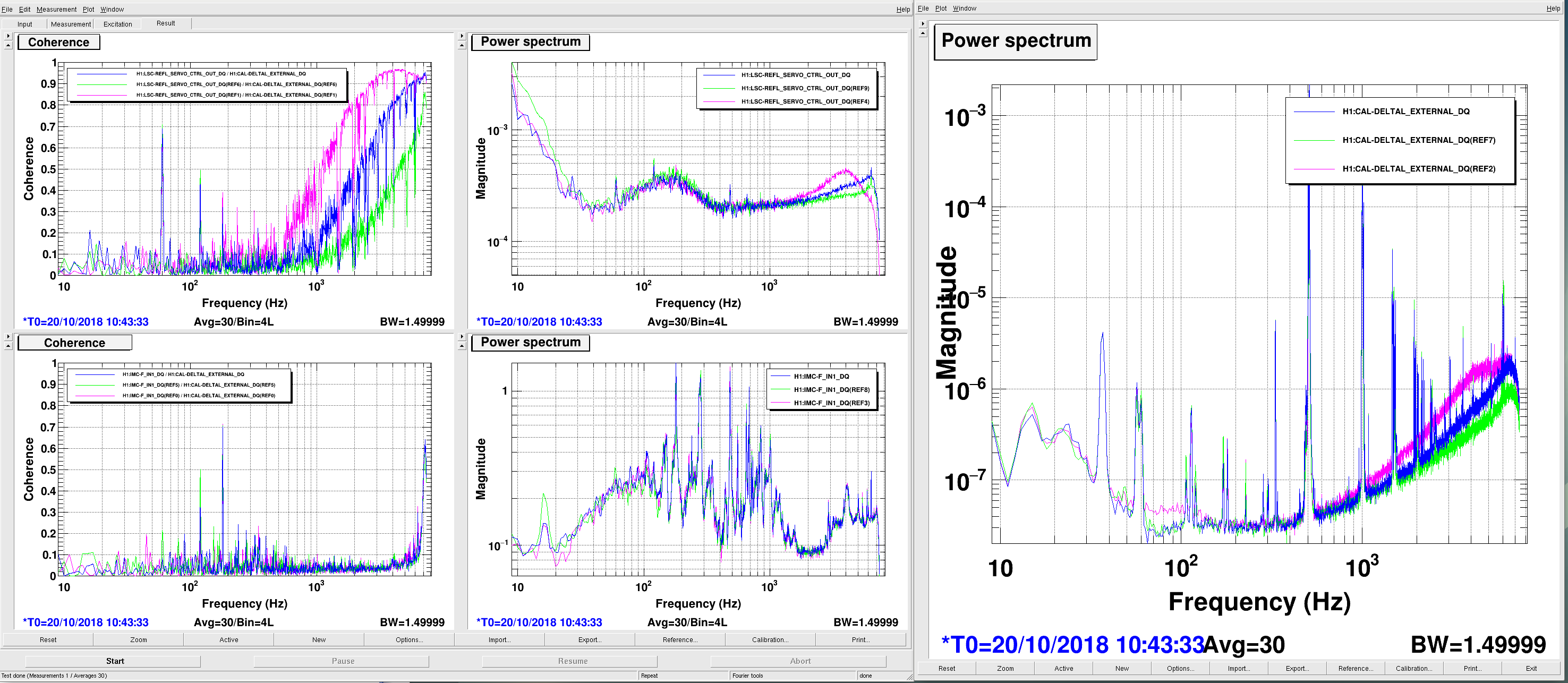
Keita and I have been thinking about the 100 Hz noise in DARM that appeared when we had low CARM gain. Tonight I reproduced the 100 Hz DARM noise in NOMINAL_LOW_NOISE. I did this by lowering LSC-REFL_SERVO_IN1GAIN by -12 dB. The second plot is DARM before and after I reduced the CARM gain by -12 dB. We can see the return of the ~ kHz noise, as well as an increase in 100 Hz and below. The first is DARM and CARM coherence before and after. This is particularly interesting: DARM vs CARM coherence is completely unchanged, even at higher frequencies. The pdf is the CARM OLG I was taking when I lost lock. CARM UGF was ~ 4.5 kHz. Unclear what could be causing this nonlinear coupling between CARM and DARM. But it is good that we can turn a knob and control this noise. It is extremely suspicious that the 100 Hz and lower noise is not coherent with anything. Further investigations when we lock again. EDIT2: I was able to relock and get another spectrum with -6 dB of CARM gain (plot 2). Unfortunately I lost lock when I reduced the IMC gain by 6 dB to try and get a DARM spectrum there. The IFO doesn't like when you take away its laser frequency control...
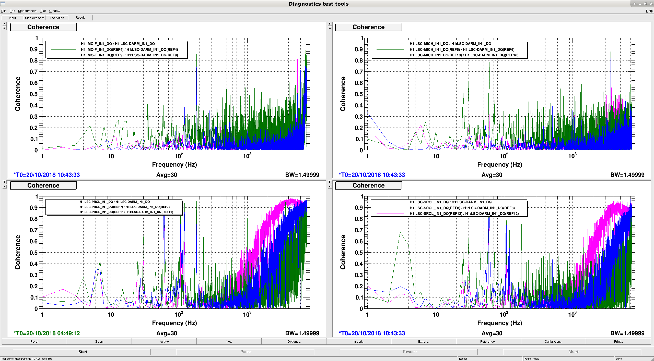
This plot shows IMC-F, MICH, PRCL, and SRCL coherence with DARM at a time of high CARM gain (green), and low CARM gain (red). It seems that PRCL and SRCL become a lot more coherent with DARM at high frequencies when we have low CARM gain. But there are no broad features at or below 100 Hz. EDIT: Added the -6 dB LSC signals. Green is normal CARM gain, blue is -6 dB, purple is -12 dB CARM gain.
"DARM vs CARM coherence is completely unchanged, even at higher frequencies"
IMC board output is not CARM (Common ARM) in that it's not what the IFO sees. It's totally dominated by the frequency noise of PSL. No change in the coherence (which is mostly f>6.5kHz) is because the residual frequency noise coming from PSL is much considerably larger than the shot noise at that frequency.
If you look at REFL CM board output you'll see that the coherence changes with CM gain.
I and Daniel went to the floor on Friday while CM was at the nominal gain and the power was 20-something W to observe REFL_A_RF9 RF monitor.
On the scope it was about 10mV pp, the monitor has 23dB attenuation so the PD output should have been about 140mVpp. The largest component was 9MHz, closely followed by 72MHz, everything else was small.
RF power monitor in the demod board sometimes shows -5dBm or so but mostly -10dBm-ish.
From INMON channels it's clear most of the remaining RF was in Q phase (note the analog whitening gain of 12dB).
Nothing stood out.
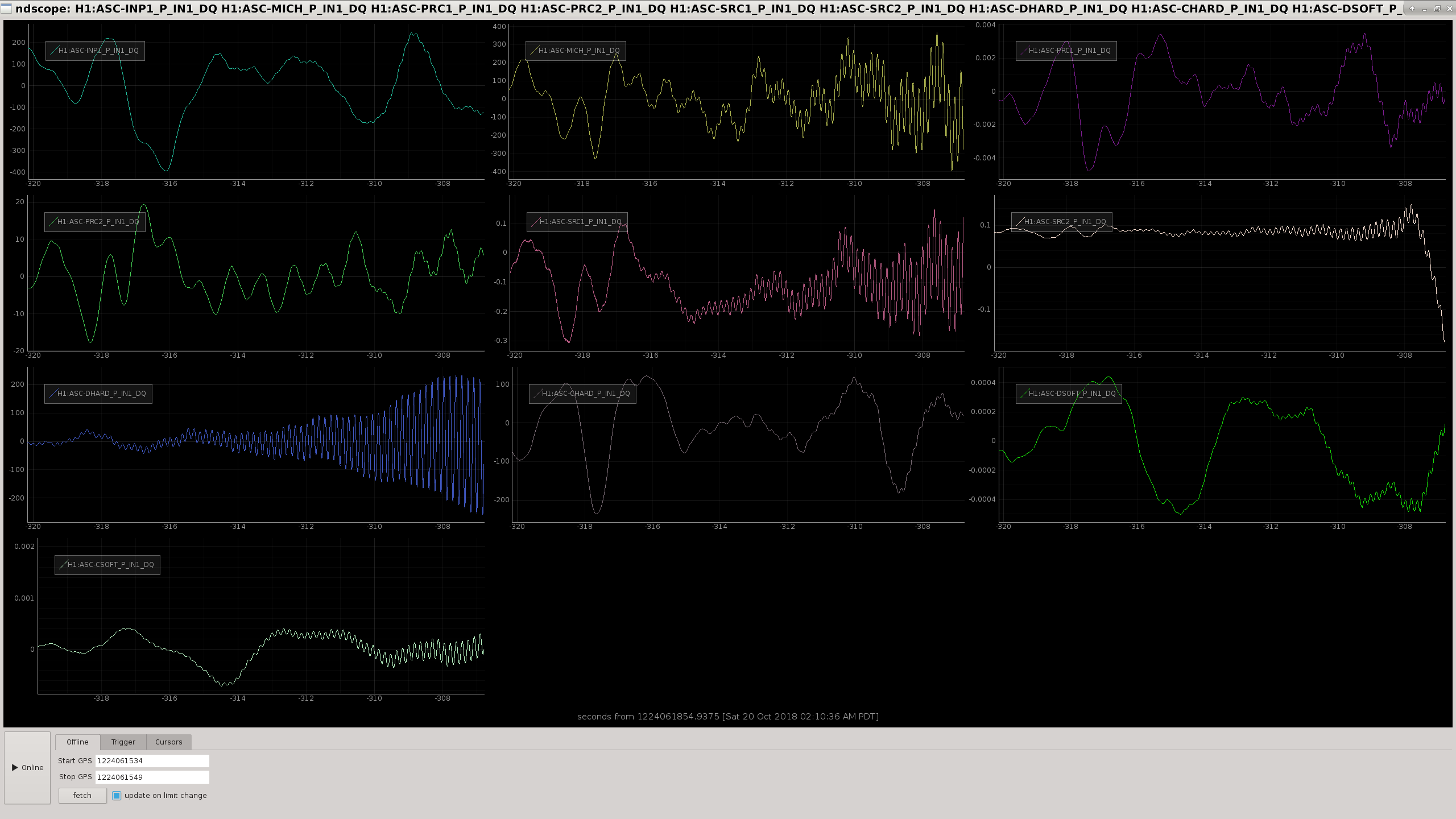
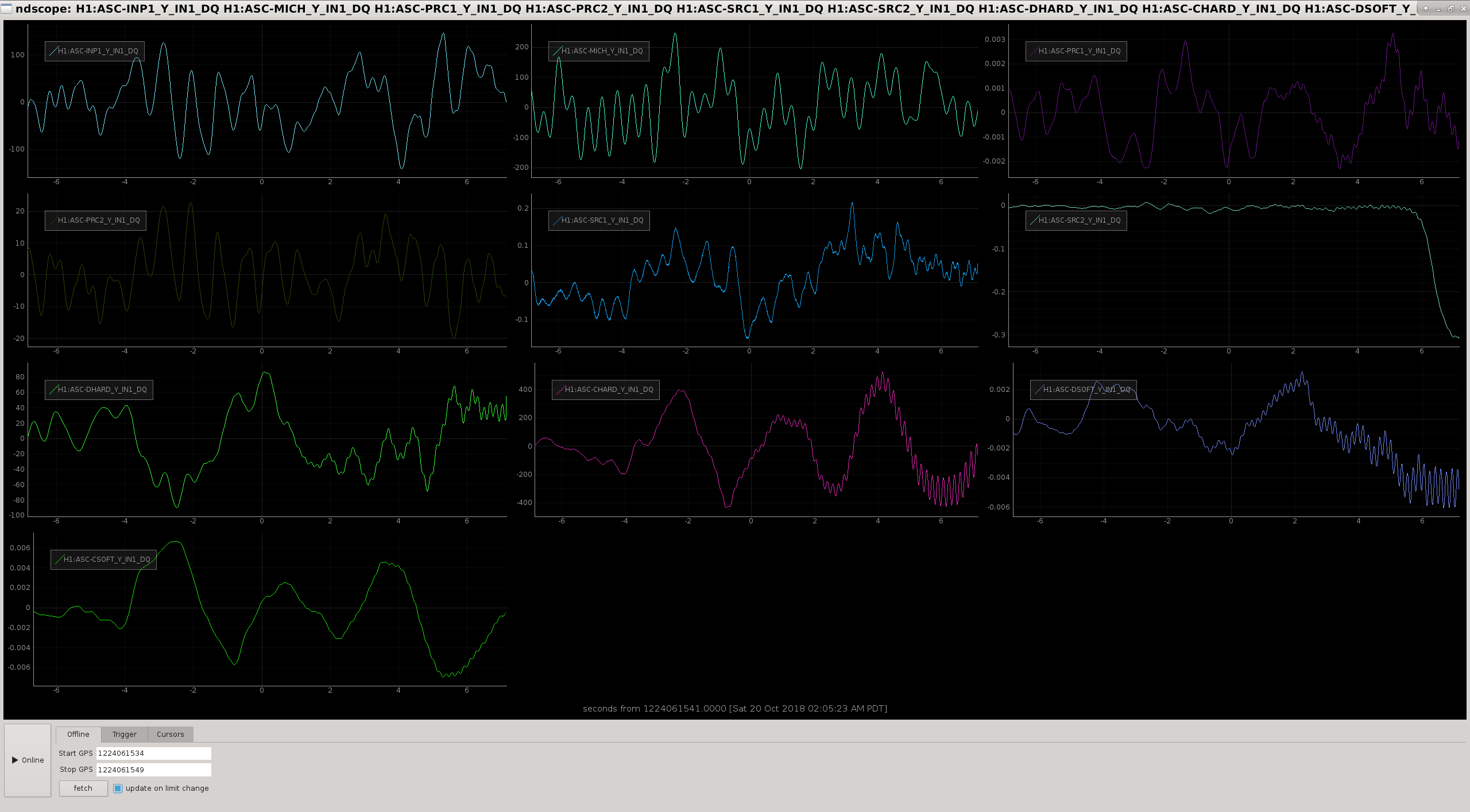
- Had to rerequest HAM2 HPI ROBUST ISOLATED state to get HAM2 ISI to ISOLATED. Then was able to lock ALS. - Got back up to NOMINAL LOW NOISE at 23 watts. - Fast lockloss - Struggled to relock ALS, something to do with X arm fiber polarization being bad. I enabled the polarization controller, which seems to spin wildly until it's shut off. Eventually it found a better polarization for the X arm. - Lockloss as soon as I entered LOW NOISE COIL DRIVERS (directly after LOWNOISE ASC). - Again, lockloss as soon as I entered LOW NOISE COIL DRIVERS (directly after LOWNOISE ASC). - Stepped through the LOWNOISE ASC state by hand and made it with no problems. Added some wait times to the state, otherwise did not change. - For a third time, lockloss at the end of LOWNOISE ASC. This time the state didn't move onto LOW NOISE COIL DRIVERS because of the waits I added at the end of the state. The problem seems to be with H1:ASC-CHARD_Y FM3 (a 40 Hz cutoff filter) being turned on, but that could just be because that's the last thing that happens in LOWNOISE ASC. Could also be because LOWNOISE ASC is happening when the IFO is thermalizing, so optical gains could be changing under our feet. Adding more, longer waits... - Fourth time lockloss at the end of LOWNOISE ASC. Could see a clear pitch oscillation on the AS camera, turns out it was a DHARD P oscillation at 6 Hz (see plot 1). Probably a loop stability issue. - In LOWNOISE ASC at 23 watts, DHARD P FM7 (some LF boost/angular suspension resonance shaper thing) gets turned on, gain goes from -50 to -40, and FM1 (a 20 Hz cutoff filter) gets turned on. - Fifth time lockloss during LOWNOISE ASC, this time while I was going through slowly by hand. The last thing I did was step 4, engaging the arm ASC cutoff filters. (I did all four at once like an idiot.) I had left DHARD P at -50 gain. No 6 Hz oscillation this time, just a quick death. - Made it through LOWNOISE ASC by turning on the cutoff filters slowly and one by one. Made guardian so that it will do it that way too. - Leaving the IFO trying to lock DRMI with NOMINAL LOW NOISE requested. Range was 60 Mpc at NLN, absolutely CRUSHED by Livingston, they are literally off the charts here at Hanford.
About the polarization controller:
Immediately after turning on the polarization controller, click the restore button. 43559 Maybe we can edit the medm screen to make this more obvious. The problem is that the controller restores the paddles to the last position that they were manually set to (by turning knobs). Patrick created the restore button so that we can use it to reset the paddles to the last position that they were set to using the remote interface.
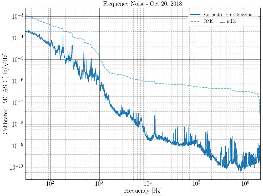
I roughly calibrated an IMC spectrum taken during one of our longer high power locks into frequency noise. This spectrum was taken with high CARM gain at 23 watts of input power. It was taken at IMC Servo Board Test1. Well informed guesses about the laser frequency control hierarchy during this measurement:MCL Crossover ~ 30 Hz CARM UGF ~ 10 kHz IMC UGF ~ 75 kHz FSS UGF ~ 200 kHzI relied on the calibration of the IMC VCO of 268302 Hz/V, times two for the doublepass AOM. There's also a VCO zero/pole of 40/1.6, the IMC Servo Board fast path signal coloring (Fast Option 200kHz pole, Fast HPF 70kHz/140kHz, and Fast Gain), and the FSS CLG. The calibration looks like this:where
is the measured IMC OLG, and
is the measured FSS OLG. (This FSS measurement is a little old, things could have changed, but the gain settings are the same: 20 dB Common and 9 dB Fast gain) I cut off the spectrum at 30 Hz because that's the MCL crossover freq and I haven't included the slow path in the model. The low frequency stuff greatly increased my RMS, but I doubt this is really the case since the suppression of MCL is insane. Frequency RMS from 30 Hz to 2 MHz: 1.1 mHz
I am baffled. If you measure at MC_F, you should see mainly frequency noise from the laser. The frequency noise of the VCO corresponds to ~1mHz/rtHz alone.
The last time I measured the FSS transfer function was back on October 9th. The gain slider settings were the same as before so I would not expect too much impact on your F(f).
Hang, Sheila, Dave, everyone
We had a repeat of this morning's crash of HAM2,3,4,5. 44678 44671
Dave walked us through the reset over the phone:
log into h1seih23 and h1seih45 as controls (ssh controls@h1seih23) (check secrets.ligo.org) run the command /etc/startWorld.sh to restart all the models on those machines. After they come back you will need to reset watchdogs and dackill.
It seems that the sensor correction gains already on this time.
If this continues to happen overnight people can do the restart this way. If it happens tomorrow during the day Dave might want to try shutting things down and starting them again, so we can give him a call.
As the proc files show, the DAC FIFOs are getting exhausted. This typically happens if the IOP cycle time is too long (so it doesn't get the DAC FIFO filled before it gets clocked out every cycle). We see a long cycle time on each (500 mu-sec) but unsure when it occurs. A common factor between seih23 and seih45 is the DACKILL IPC from IOP model on sush34, or it could be a DC power supply. I would definitely recommend I/O chassis power-cycle (or at least a front-end computer reboot). As I understand it, the SEI HAM front-ends have newer (2012 production) PCIe expansion fibers, so we hope they are not degrading.
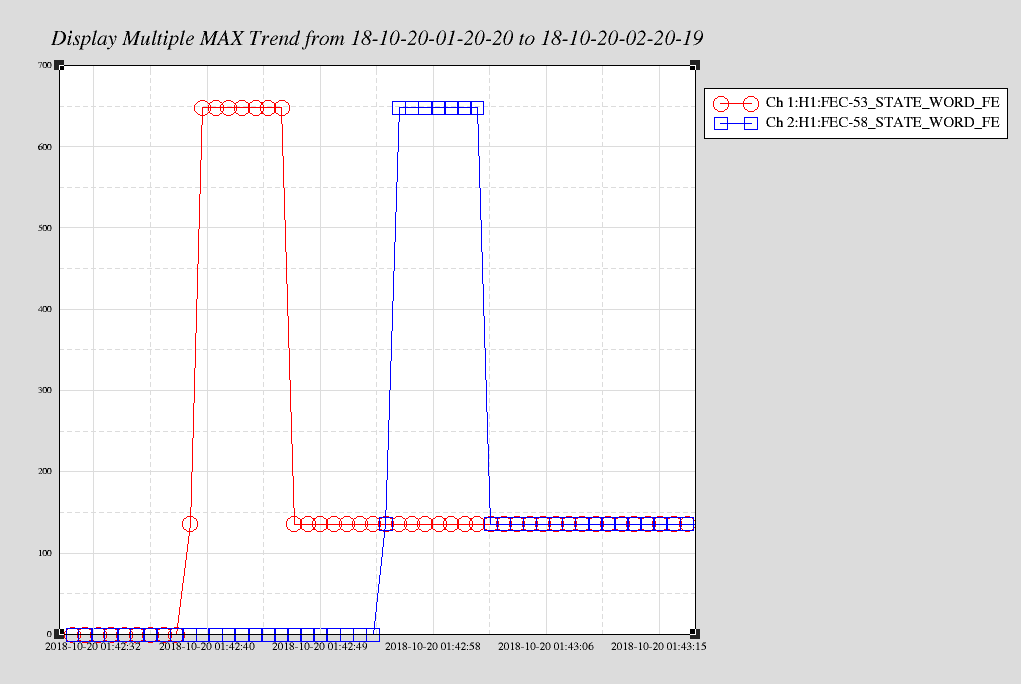
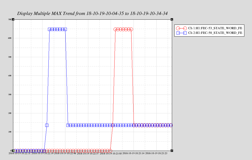
Attached image show the state_word for h1iopseih23 (red) and h1iopseih45 (blue) as a second trend around the time of the problem.
The sequence is:
h1iopseih23 goes to DAC+DK for 1 second, then goes into DAC+DK+OVR for 7 seconds
h1iopseih23 returns to DAC+DK and stays there
7 seconds later, h1iopseih45 follows the same sequence.
Attached plot shows situation during this morning's 03:29 crash, same general sequence but the IOP order is reversed.
The iop models on h1seih(23, 45) went into a DAC+DK error state this evening. This is covered by the FRS opened for this morning's 03:29 event FRS11680
Before restarting the models, I captured the /proc/h1seih(23,45)/status files (and tailed the dmesg). The models were restarted using the /etc/startWorld.sh script.
If this problem persists, we should consider a power cycle of the IO Chassis. It is not clear how h23 and h45 are paired, I'll take a look at the Dolhin IPC table.
Patrick Godwin, Sheila Dwyer
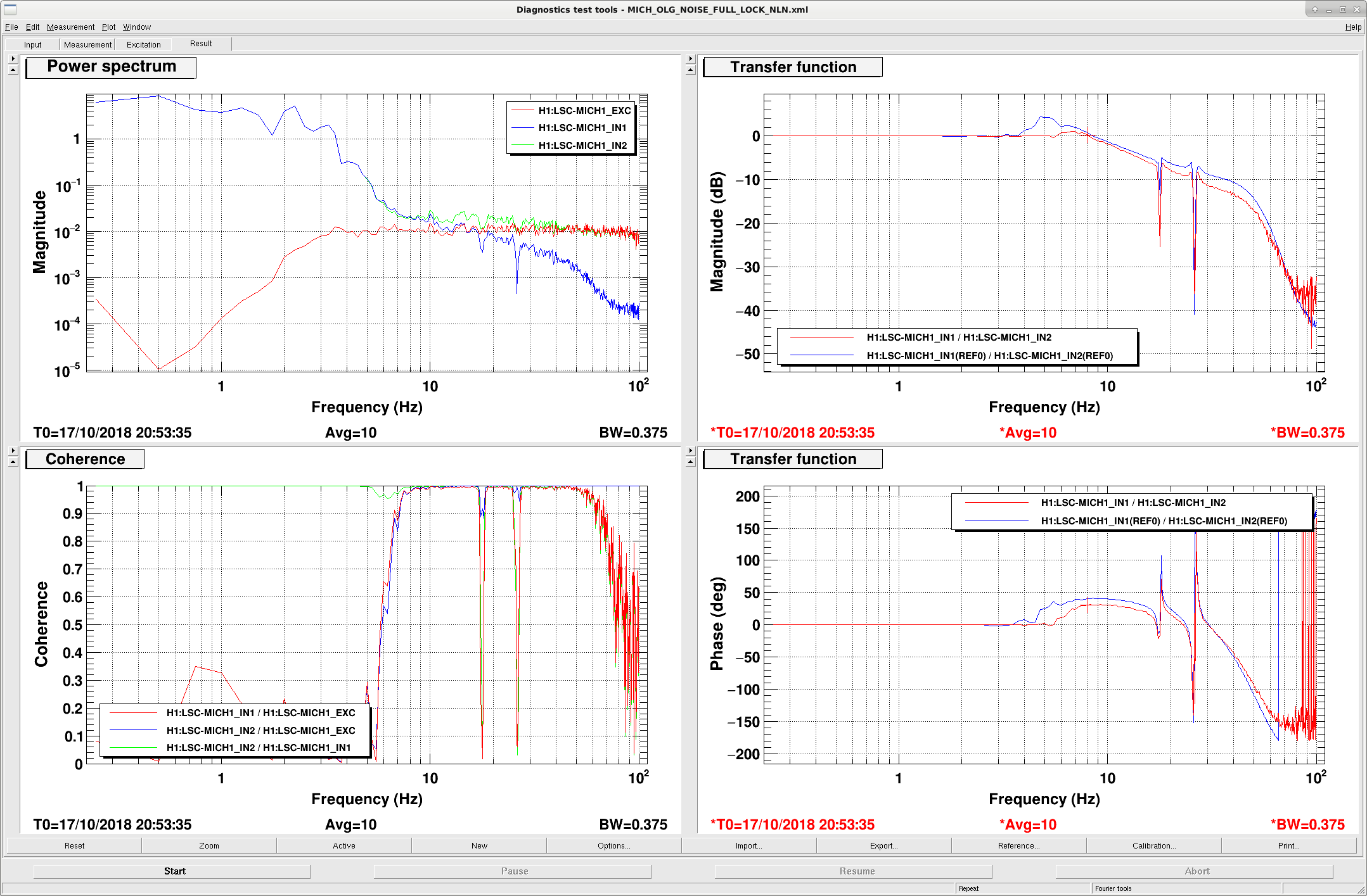
We looked into why the POP45 whitening gain had to be reduced compared to O2 (44420) ; we are now engaging MICH filters which give us less gain at low frequencies compared to O2, and our resulting residual RMS is 4 times higher than it was. We saw that REFL45 also is saturating it's ADC using the lockloss code addition that Patrick recently wrote to check for ADC saturations.
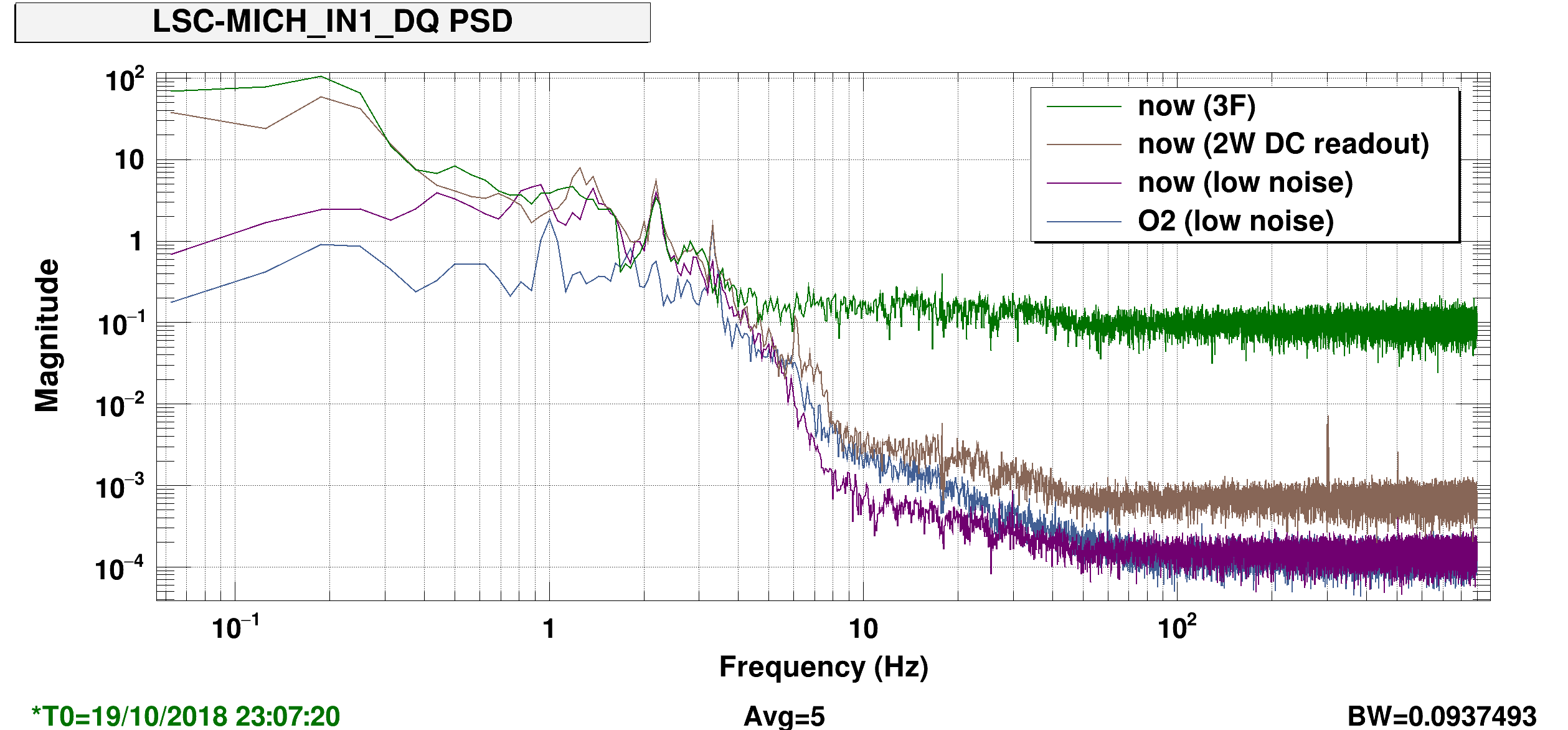
Patrick found times in the past to compare the MICH error signal (see first attachment). During O2 the noise below 3 Hz is much lower, the higher noise now is present in several states, including locked on 3F and before the ASC is engaged.
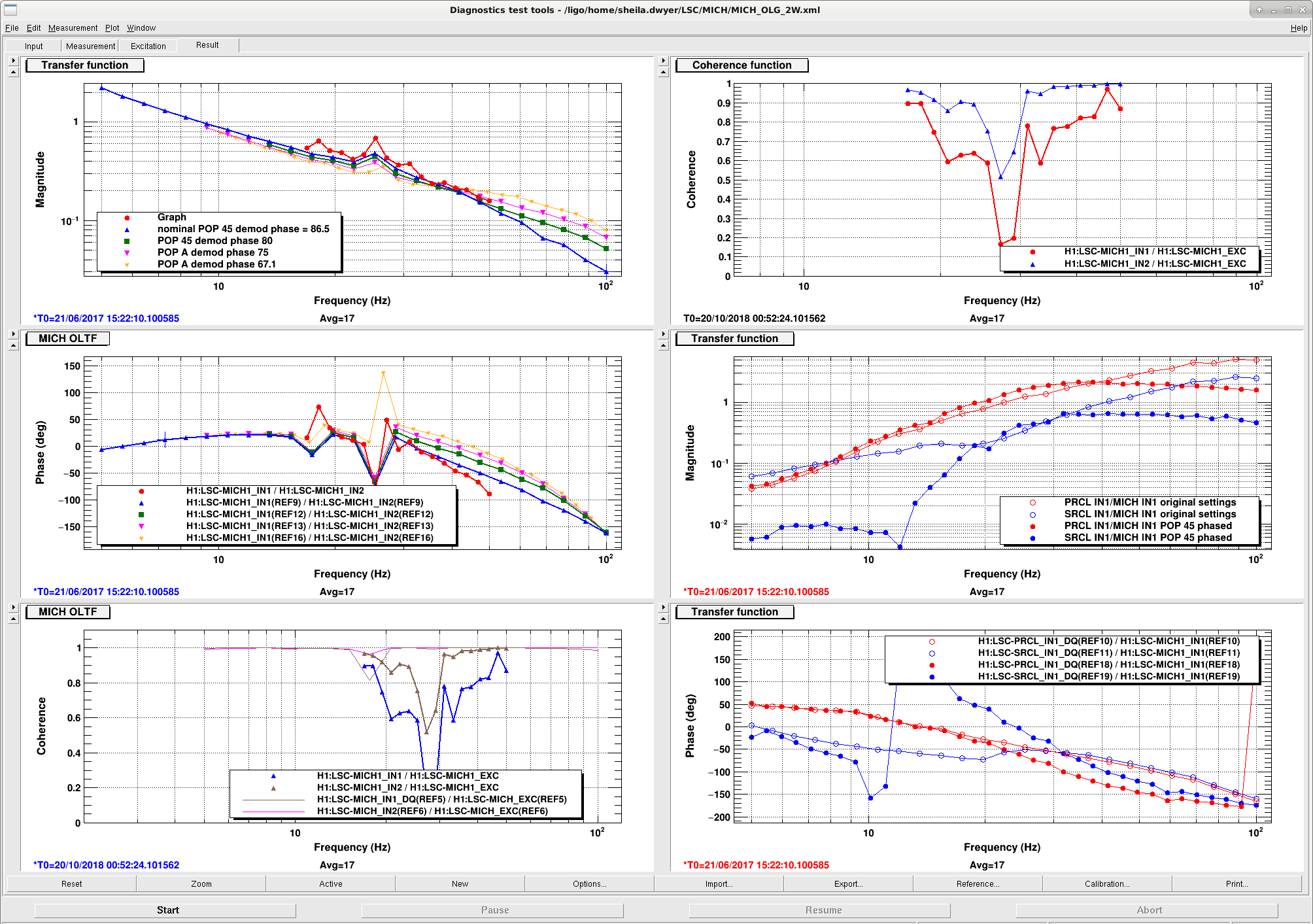
The next two attachments show open loop measurements taken during O2 (see the blue trace) and recently. The UGF used to be a little higher, 9 Hz, and we used to have less phase.
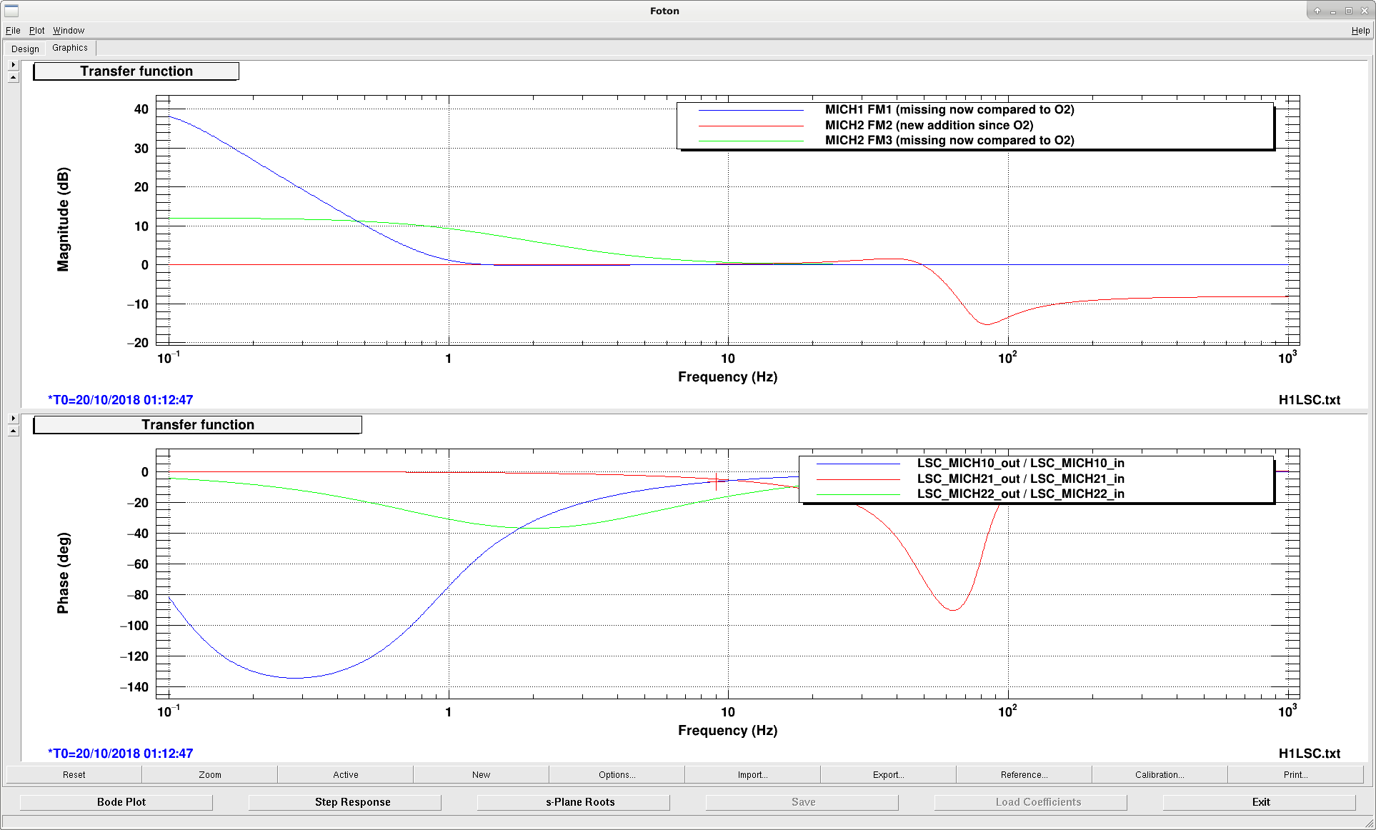
Patrick and I found that the MICH filter states are different: MICH1 we are no longer using the boost in MICH2 FM3, there is a cut off filter engaged in FM2 that was not used in O2 which eats some phase. In addition there was a boost in MICH1 FM1 which was engaged in O2 but is not engaged now. The last screenshot shows a comparison. We haven't gone back in the filter archive to check that the filters aren't changed since O2.
We should try to restore this MICH configuration soon (before we try any more FF tuning). We can't try it now because of seismic computer problems.
Jeff K., Evan G., Lilli S. Summary: The suspension actuators which are used to control the differential arm degree of freedom are calibrated from measurements using the Pcal as a fiducial. Currently, DARM feeds back to L3 on ETMX, L2 on ETMY, and L1 on ETMY. Our measurements are within ~5% of the nominal O2 values. Details: This is to explain the SUS actuator calibration measurements from LHO aLOG 44507 in more detail. We processed the measurements using the pyDARM code which lives here: /ligo/svncommon/CalSVN/aligocalibration/trunk/Runs/O3/H1/Scripts/process_actuationmeas_20181010.py Results and comparison with O2: Parameter | Quantiles (0.15, 0.50, 0.84) | Nominal O2 value | % change -------------------------------------------------------------------------------------------------------- EX TST Actuator gain, H_c (N/ct) | 4.502e-12, 4.505e-12, 4.508e-12 | 4.357e-12 (ETMY) | +3.4% Residual time delay, tau_A (usec) | 4.794, 5.896, 7.014 | | | | | EY PUM Actuator gain, H_c (N/ct) | 6.484e-10, 6.508e-10, 6.531e-10 | 6.768e-10 | -3.8% Residual time delay, tau_A (usec) | 71.18, 79.91, 88.83 | | | | | EY UIM Actuator gain, H_c (N/ct) | 8.513e-08, 8.535e-08, 8.557e-08 | 8.091e-8 | +5.5% Residual time delay, tau_A (usec) | 102.3, 112.2, 121.9 | | Note that the residual delay is poorly characterized on the L2 and L1 stages because we didn't go to high frequencies and we made so few measurement points. Further characterization is necessary in order to better determine the residual delay. While the MCMC is able to precisely determine a residual time delay value, it is skewed by our lack of data (in O2, we used the L3 stage only to establish this delay, which was consistent with zero, and we don't expect that it has changed). Unfortunately, we have to pay attention to the different delay in different stages because we are actuating on different test masses that have distinct computers. We drove at a new excitation point (see LHO aLOG 44459) that is parallel to the calibration lines at the input to the DRIVEALIGN bank. This new location captures any potential changes in the DRIVEALIGN bank gain (e.g., when the ESD bias sign is flipped) and allows us to back out measurements to a reference model time by using the time varying "kappa" values derived from calibration lines. Attached are several figures to show the analysis: 1) All three actuation stages and residuals where the measurement is from the input to the DRIVEALIGN bank to meters DARM where we have removed the frequency shaping of the DRIVEALIGN filters but left the gain in place. This is the traditional "actuation strength" measurement and comparable to O2 measurements at the TEST excitation point. 2-4) Each actuation stage with the frequency dependence divided out, leaving only the gain of the actuation path (N/ct). The gain measurements and residuals (measurements/model) are shown. 5-7) Corner plots showing MCMC results which determine the gain and delay with uncertainties (shown in the above table) 8-10) Gaussian process regression fits to the residuals. With further measurements (expanded frequency bands, higher precision measurements, etc.) we can easily refine the unknown systematic errors. For example, if we better characterize the UIM suspension dynamics, then we can remove this systematic effect and utilize more frequency points from the UIM above 50 Hz. We have put together a schematic diagram showing the sign conventions along the actuation paths. Just along the three SUS actuation paths and Pcal paths there are >30 possibilities for sign flips. You can't just flip signs and guess to get the right answer because we are making injections at several different points in the control loop. We actually have to understand and validate each one in the loop. We are confident that the actuator signs are correct because they match O2 measurements (see LHO aLOG 44691). #BookkeepingNightmares Although the actuation strengths are roughly comparable to the O2 values, when we install these into the front end for control room calibration, we find that the DARM spectrum is incorrect by a factor of ~2.6 at 37 Hz (see LHO aLOG 44507). We need more time with the instrument in order to sort out what could be going wrong.
at 16:11 PDT I restarted the h1broadcast0 GDS broadcaster. The new INI file has 37channels removed which no longer exist, and 54 new channels added. The new channel list is defined in DCC-T1800452. Note that of these, many of the fast channels were already in the broadcaster.
This closes WP7866.
TITLE: 10/19 Day Shift: 15:00-23:00 UTC (08:00-16:00 PST), all times posted in UTC
STATE of H1: Commissioning
INCOMING OPERATOR: None
SHIFT SUMMARY:
LOG: (see attached)
FRS11679 I verified that it was possible to load filters into other ISS filter-modules (FM), so there appears to be something special about the ISS_SECONDLOOP_REFERENCE_DIFFRACTION_CAL FM. Gabrielle confirmed that for the past 6 months no filter was shown on this FM, and he was surprised to find filters defined for this FM in H1PSLISS.txt.
The first thing which struck us was the long name length. Of the 12,733 filter modules in H1, only 3 have name lengths of 40 characters. The FM list below is sorted by name length (last few lines shown).
To test, I tried to load a filter into CS_DARM_TDEP_CORR_DELTAL_RESIDUAL_WHITEN, which also failed.
WP7881 covers shortening the names of these three FMs and verifying filters can then be loaded.
37 SIM_ITMY_SUB_DEFOCUS_FULL_SINGLE_PASS
39 CS_DARM_TDEP_CORR_DELTAL_CTRL_L1_WHITEN
39 CS_DARM_TDEP_CORR_DELTAL_CTRL_L2_WHITEN
39 CS_DARM_TDEP_CORR_DELTAL_CTRL_L3_WHITEN
39 CS_DARM_TDEP_CORR_DELTAL_CTRL_M0_WHITEN
39 VAULT_SEIS_1030X195Y_STS2_X_BLRMS_INPUT
39 VAULT_SEIS_1030X195Y_STS2_Y_BLRMS_INPUT
39 VAULT_SEIS_1030X195Y_STS2_Z_BLRMS_INPUT
40 CS_DARM_TDEP_CORR_DELTAL_CTRL_SUM_WHITEN
40 CS_DARM_TDEP_CORR_DELTAL_RESIDUAL_WHITEN
40 ISS_SECONDLOOP_REFERENCE_DIFFRACTION_CAL
This unit is a Varian SQ051 serial number #70125. I did this in the LEAA. Tested both internal pumps - excellent!
HAMs 2, 3, 4, 5 are tripped both HEPI and ISI. I tried resetting HAMs 2 & 3, and they both re-tripped.
At first glance, it looks like maybe there was a timing glitch, a la alog 43806.
[RichardM, Jenne, KeithT via phone]
I requested all HEPI and ISI guardians for HAMs 2, 3, 4, 5 to "READY", then we restarted all the models on those computers.
I ssh'ed to the computers, h1seih23 and h1sei45, and ran "sudo /etc/startWorld.sh". Richard clicked some DACKILL reset buttons, and we're back. I requested the HEPIs and ISIs to their nominal states, and have started initial alignment.
The BLRMS that Jim has on the wall for HAM5 (alog 44661) look high, but I'm going to wait until he gets in to look into this - it's not stopping me so far.
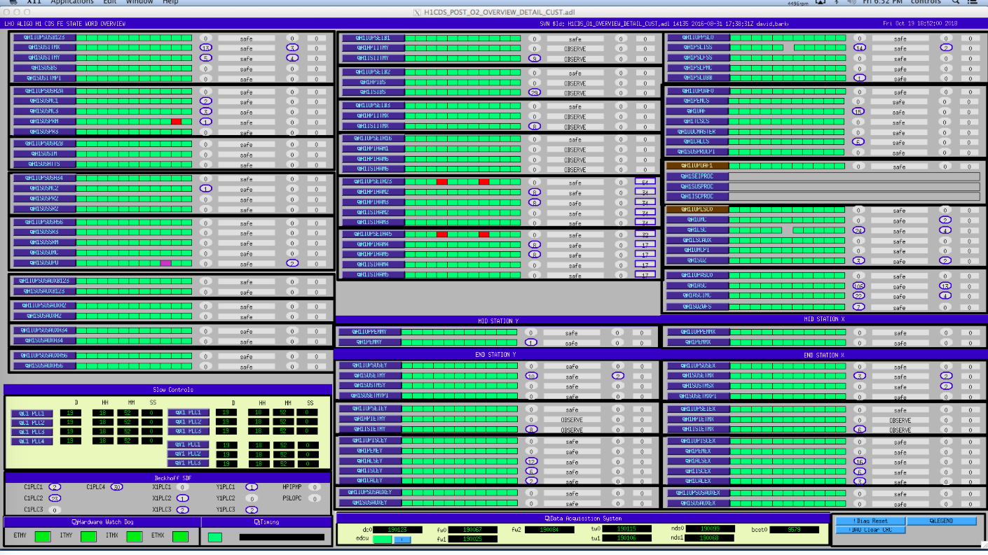
Gabriele and Sheila had said that locking had been not very robust today, so I checked on the status of the ISIs. Restarting the ISI models zero'd all the gains on the sensor corrections on these ISIs (that was how Hugh and I set them in the safe.snap). The HAM sensor correction guardians didn't re-engage the sensor correction after the restarts. I found this by looking at some lights I added to the SEI_CONF overview. On the attached screenshot, there are a bunch of green indicator lights about a third of the way up from the bottom left corner, where it says "Sensor Correction Gain States". The only red light now is for the EX sensor correction, which is off because of the broken BRS. I guess I haven't advertised this before, but if there is a question about the seismic configuration, this screen is a good place to start. The sensor correction lights don't show everything, but should all be green if we expect everything to be nominal.
Danny, Sheila
Concerning the A2L script, I could not reproduce the problem. My best guess is: sometimes the online NDS connection returns bad data for the first second. So I modified the script so that it discards the first chunk of data it receives.
I also added a check on the arm transmitted power: if LSC-TR_X_NORM_IN is lower than 1000, then the script stops the measurement, since the IFO is likely unlocked.
If the script fails again returning NaNs, you can simply try to run it again.
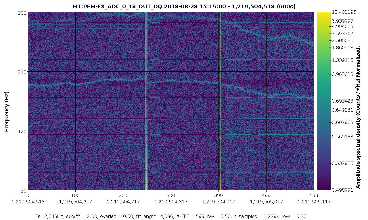
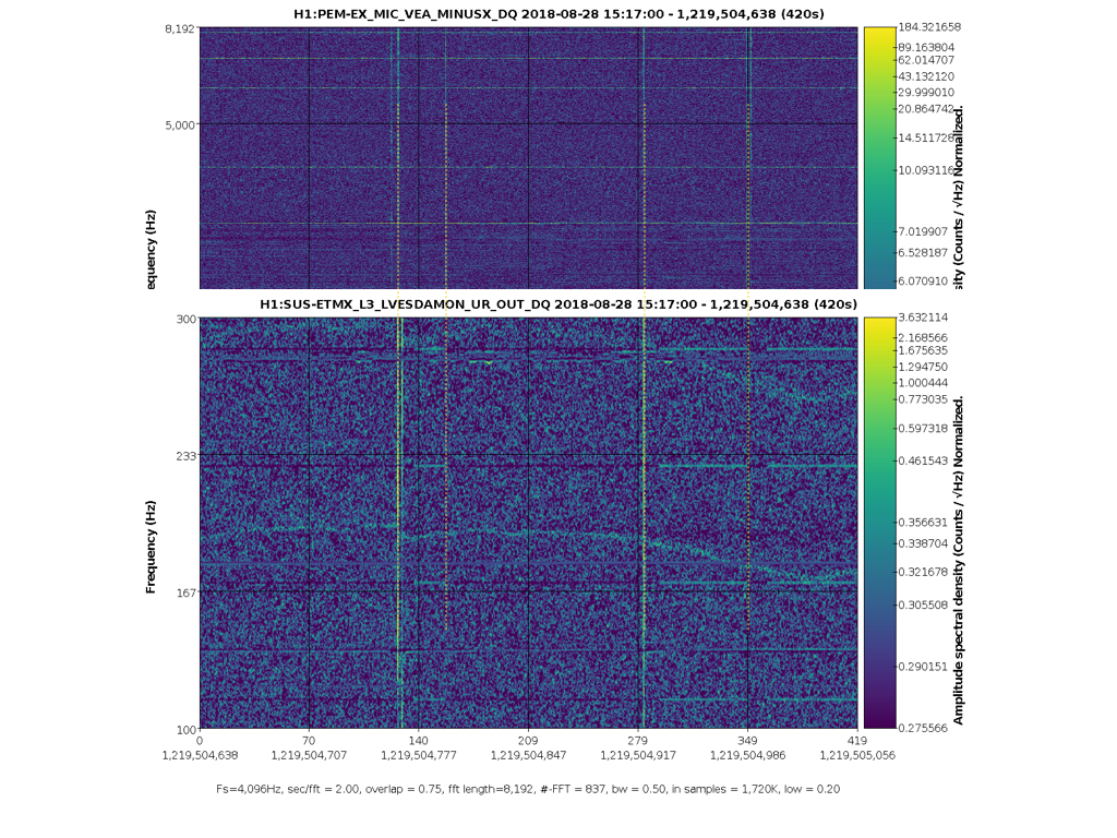
There is a comb in h(t) at 56.84044 Hz and multiples, identified in the Oct 11 low-noise data, with extreme amplitude modulation. In alog 44495 and follow up, it is found to be in many EX channels, including unused ADCs in the PEM system. The time when this line began has now been tracked to August 28 15:20 UTC. The attached spectrogram shows the lines appearing. The most likely cause that I can see in the alog is an update of the TwinCAT system manager on h1ecatx1. This is logged as starting at 14:54 UTC (alog 43706, and alog 43697 seems to indicate that the restart happened at 15:20 UTC.
I've found that there are sounds in the EX MINUSX mic related to the 56.84 Hz line beginning. There are a number of clicks, which sound like a door being opened or electronics boxes being opened. At each one, the 56.84 Hz either appears or disappears or there is a broadband glitch in the electronics. So it seems that the reboot is not the cause, rather something was jostled. Attached are a spectrogram, and an MP3 of the microphone, in case anyone recognises the sounds. I didn't see anything in the other PEM mic signals at EX.
Andrew, what a nice observation. It sounds like an electrical relay contact opening and closing to me. I don't know where this microphone is physically located in proximity to the air conditioning equipment for the EX VEA, but a component of that system is the first thing that comes to mind. Perhaps the heaters that are part of the dehumidification and temperature control scheme? Are you able to see correlation of the glitches iin the magnetometer?
There's a map and a picture of the location on pem.ligo.org. It looks like it's under the beam tube, near the floor. Since Aug 28, I haven't found any time where the line goes away in the ADC. It wasn't there before those noises, and it also hasn't changed since. We could check this in more detail if needed (I've just chosen a few dozen times at random). Was there anyone at End-X at this time (Aug 28 15:20 UTC), or was all of the work remote?
FYI, 56.8Hz and its harmonics were present in DCPDs last night even when there was no light, though the amplitude when dark was much much smaller than in-lock.
Red and blue are when IFO was locked with 20W, green and brown are when IFO was left unlocked last night and no meaningful light was coming to AS port.
Maybe this is a potential problem for all stations, just that it got much worse at EX on Aug 24?
Nice catch, Keita! I think this may be the cause of the amplitude modulation. The EX comb is at 56.84044 Hz, and the CS has a comb at 56.84078 Hz. DARM, in lock, seems to be a mixture of the two. I've found this comb in a few of the apparently unused ADCs for the CS PEM. The frequency is the same as seen in the DCPD when it's dark, as pointed out by Keita. The line is very stable and can be well-separated from the frequency in EX, especially when looking at the higher harmonics. The first plot shows these two lines in the ADCs. EX is marked by the red vertical line and CS by green. The second plot compares the DCPD when dark and in lock. Only the CS line is evident when dark. When in lock, it's harder to resolve the lines since there's not as much data. But it is clear that the CS line disappears. But now there are symmetric sidebands around where it was: one matches the EX line, and there's a new line marked blue which is mirrored across the CS line. The separation of these matches the amplitude modulation seen in DARM with a 50-minute total period. It's hard to understand the exact mechanism here, and why the central line should disappear. It does seem that both CS and EX have combs but they can be distinguished by the precise frequency (needs 0.1 mHz resolution).
Evan G., Jeff K. Summary: The calibration measurement data that was collected yesterday has now been analyzed using our Markov Chain Monte-Carlo (MCMC) methods. We detail the results below. Nothing abnormal was found, and we find that the time varying factors can track changes in sensing gain and coupled cavity pole and actuation coefficients. Details: We analyzed the data collected during yesterday's calibration measurements, see LHO aLOG 35849. We have simplified the process for analyzing the data; rather than running two separate Matlab script to generate the MCMC results, we can now run just one script to get the final model results. For the sensing function, we run ${CALSVN}/trunk/Runs/O2/H1/Scripts/SensingFunctionTFs/runSensingAnalysis_H1_O2.m while for actuation, we run ${CALSVN}/trunk/Runs/O2/H1/Scripts/FullIFOActuatorTFs/analyzeActuationTFs.m. Note that for the actuation calibration script, we have not yet converted it to an IFO agnostic script. Once it is converted, this script will be renamed. Below are the table of values and their associated uncertainties for yesterday's measurements. Also, for comparison, are the modeled values from the reference measurement 3 Jan 2017: Reference Value MAP (95% C.I.) MAP (95% C.I.) 2017-01-03 2017-01-03 (MCMC) 2017-04-27 (MCMC) Optical Gain K_C [ct/m] 1.088e6 1.088e6 (0.0002e6) 1.124e6 (0.0002e6) Couple Cav. Pole Freq. f_c [Hz] 360.0 360.0 (7.6) 343.4 (2.6) Residual Sensing Delay tau_C [us] 0.67 0.67 (6.7) -1.8 (1.8) SRC Detuning Spring Freq. f_s [Hz] 6.91 6.91 (0.1) 7.4 (0.04) Inv. Spring Qual. Factor 1/Q_s [ ] 0.0046 0.046 (0.016) 0.009256 (0.0069) UIM/L1 Actuation Strength K_UIM [N/ct] 8.091e-8 8.091e-8 (0.2%) 8.0818e-8 (0.18%) PUM/L2 Actuation Strength K_PUM [N/ct] 6.768e-10 6.768e-10 (0.02%) 6.795e-10 (0.08%) UIM/L3 Actuation Strength K_TST [N/ct] 4.357e-12 4.357e-12 (0.02%) 4.537e-12 (0.07%) UIM/L1 residual time delay [usec] n/a n/a 29.1 (35.5) PUM/L2 residual time delay [usec] n/a n/a 7.7 (3.1) TST/L3 residual time delay [usec] n/a n/a 10.2 (1.8) These values are derived from MCMC fitting to the data values. The attached plots show these results for the sensing and multiple-stage actuation functions. We have added a new feature to the MCMC analysis, modeling the residual time delay in actuation. We expect to have zero usec of residual time delay, provided the model accurately captures all dynamics of the actuation. Deviations from zero can reveal un-modeled dynamics. For example, the PUM and TST residual time delays are inconsistent with zero usec, but we expect that this is due to imperfect modeling of the complicated violin resonances of the quad suspension. The time varying factors are doing a good job tracking the changes between the reference model and the currently measured parameters (see time varying factors summary page). For reference, the parameter files were used as follows: ${CALSVN}/trunk/Runs/O2/H1/params/2017-01-24/modelparams_H1_2017-01-24.conf (rev4401, last changed 4396) ${CALSVN}/trunk/Runs/O2/H1/params/2017-04-27/measurements_2017-04-27_sensing.conf (rev4596, last changed 4596) ${CALSVN}/trunk/Runs/O2/H1/params/2017-04-27/measurements_2017-04-27_ETMY_L1_actuator.conf (rev4596, last changed 4596) ${CALSVN}/trunk/Runs/O2/H1/params/2017-04-27/measurements_2017-04-27_ETMY_L2_actuator.conf (rev4596, last changed 4596) ${CALSVN}/trunk/Runs/O2/H1/params/2017-04-27/measurements_2017-04-27_ETMY_L3_actuator.conf (rev4596, last changed 4596)
A typo in the reference values for 1/Q_s above. It should be 0.046 (not 0.0046 as typed above).
For a bigger picture look at these 2017-04-27 actuation function measurements, I attach a plot of the model against measurement *before* dividing out the frequency dependence. This helps discern what the overall phase of the actuator stages should be relative to each other during O2.