I added another lock state called "LOCKED_ON_DUAL" to the existing OPO guardian. In the path to this state it will scan the OPO PZT while triggering on both normalized green trans and 6MHz RF mon. So CLF is required for locking. If seed is needed, just switch the fiber after locking OPO with CLF. Now that we're sitting at a much better nlg region compared to the last time we locked CLF, I turned down the CLF input power so the 6MHz doesn't saturate and to prepare for another LO locking attempt without saturating the homodyne.
Currently .8 mW goes into CLF fiber coupler, CLF refl sees 0.6 mW and roughly 10 uW is going to the homodyne.
Around 18:40UTC, on 8/27, MC2 starts to move in pitch, and WFS tries to hold it in place.
The PZT and the ISS QPD show some changes, most notable the PZT drift changes direction, for both pit and yaw.
My GigE cameras show drift, and some "faster" changes, in X ands Y, but more notable are the SUM plots, though it starts earlier, around 16:30UTC.
Other DC channels see the changes too.
Last plot is just MC2 pitch and yaw.
Sheila, Georgia
I ran the old optical lever effective bias measurements on ETMX and ETMY, as well as my four-parameter measurement on ETMX, and the bias drive to optical lever coupling (from which beta+beta_2 pitch and yaw can be calculated) on ETMY.
Trends of the 3 main measurements attached. First plot is ETMY V_eff for the 3 working quadrants, which is quite boring and stable (yay!), but with a large magnitude compared to ETMX.
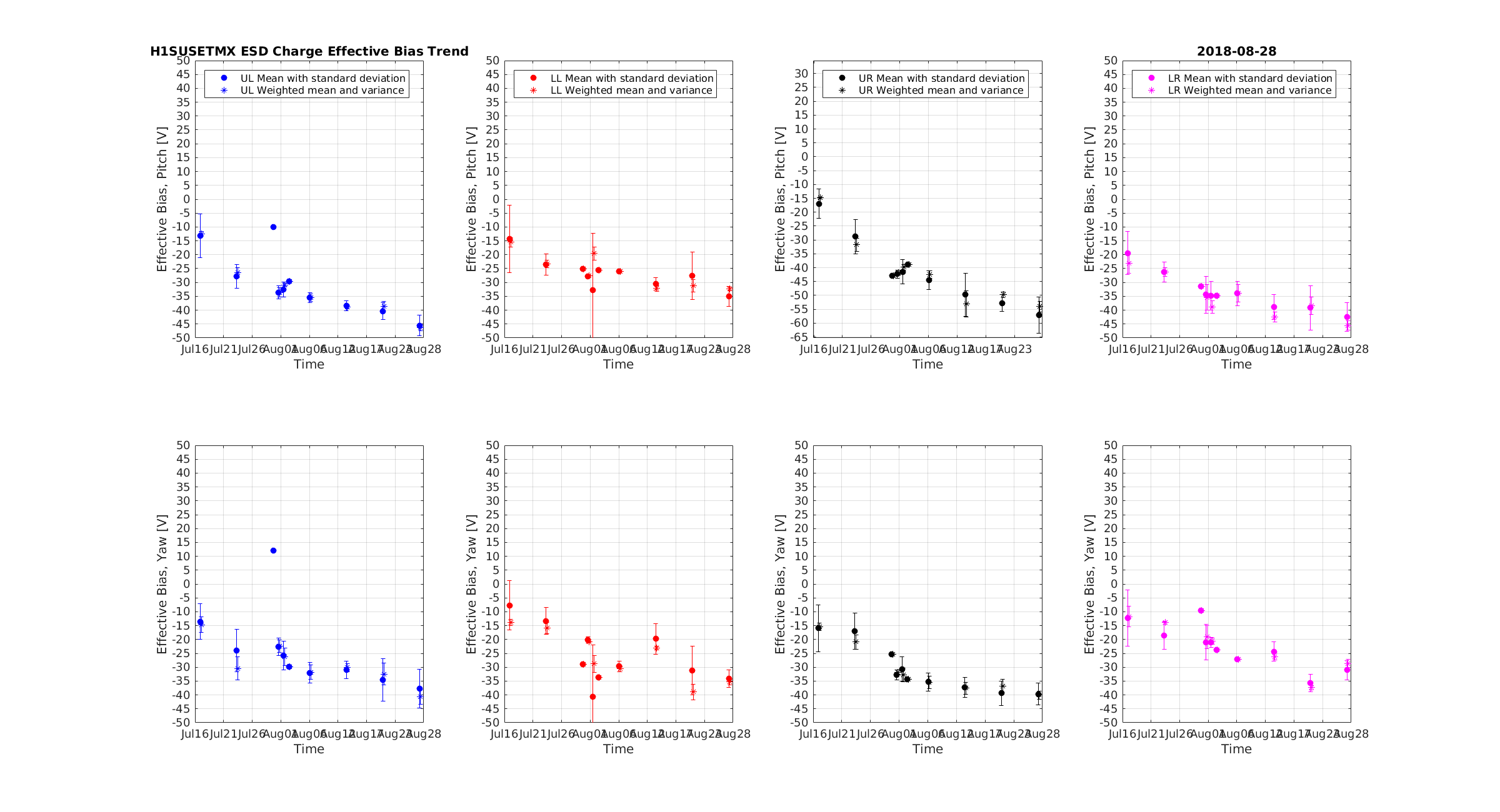
Second plot is ETMX V_eff for all four quadrants pitch and yaw. General trend is away from zero bias voltage, reminiscent of space charge polarisation. Charge due to space charge polarisation building up on ETMX has been mitigated by switching the sign of the ESD bias, causing the slope of the V_eff trend to change signs.
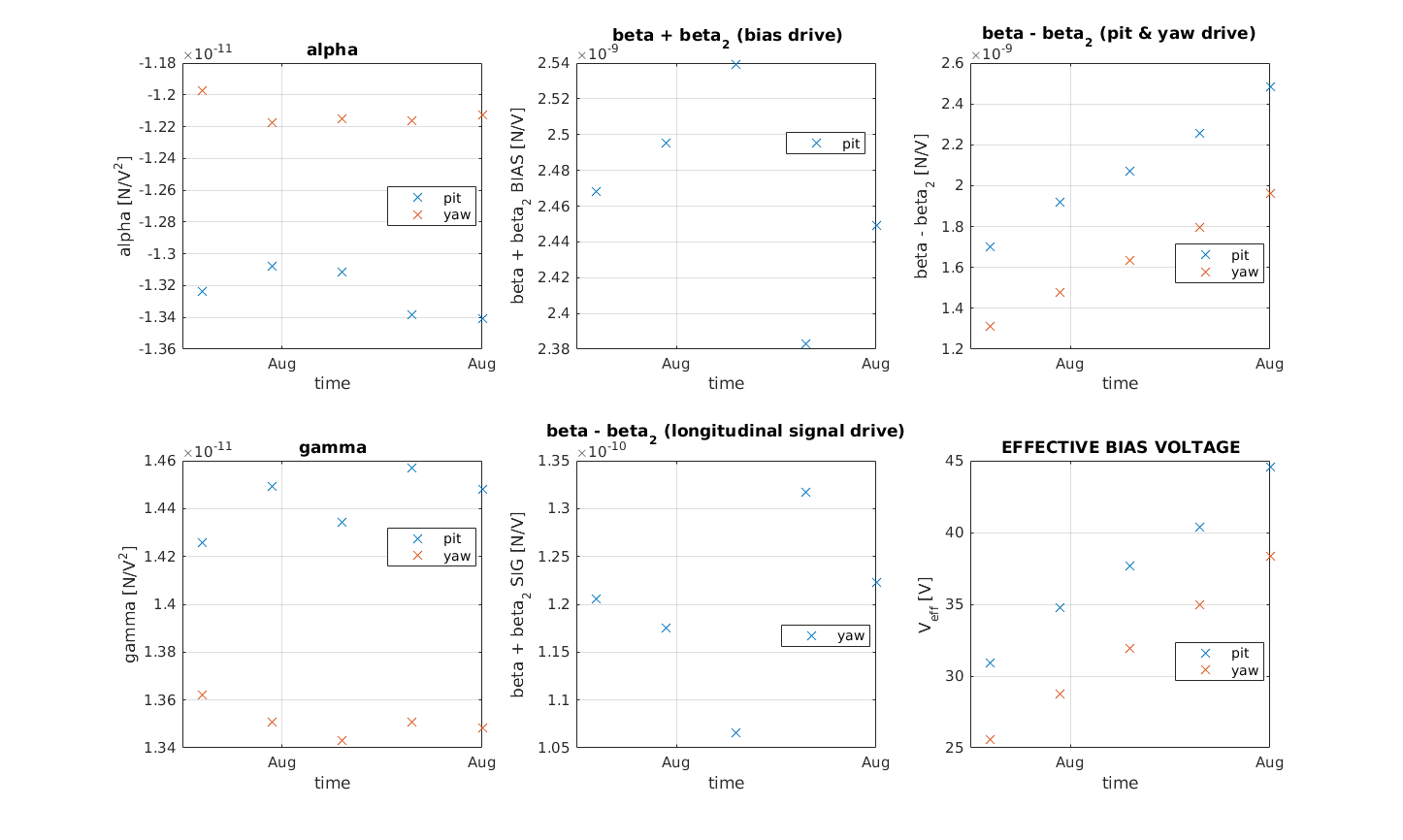
Third plot is the 4-parameter measurement, there are a few things we can take from these plots:
1. The difference in the size of alpha measured for pitch and yaw we think can be explained by the ESD layout, and the additional path around the barrel of the optic taken by the lower quadrant electrodes. When driving pitch the upper and lower electrodes are driven in common, but while driving yaw they are driven differentially. The potential difference between the upper electrode and the part of the lower electrode next to it on the barrel of the test mass could reduce the actuation strength in pitch.
2. The Beta - Beta_2 pitch and yaw, and V_eff measurements sensitive to space charge polarisation and are consistent with the old quadrant-by-quadrant Veff measurements. I probably have messed up some signs and am not too worried about the discrepancy there as the magnitude of the effective bias voltage is consistent.
3. The Beta + Beta_2 (bias) and Beta - Beta_2 (longitudinal) are longitudinal measurements and should not be sensitive to space charge polarisation. If the localised charge on the test mass is low, these drives should not couple to pitch and yaw on the optical lever. The centre top plot suggests that there is some source of charge on the same order of magnitude as that due to the space charge polarisation, coupling to pitch when the bias is driven and to yaw with the signal is driven, I'm not sure why these would be different between longitudinal signal drive and bias drive.
4. The Beta + Beta_2 (bias) is much larger than the Beta - Beta_2 (longitudinal), suggesting greater coupling to the bias electrode. Note that this is what we would expect if charge was localised around a bump stop, as the bias electrode passes closer to the bump stop.
Finally, analysing the op lev data while driving the ETMY bias gives:
Beta + Beta2 (p) = 4.4e-09
Beta + Beta2 (y) = 3.2e-08
This is consistent with last week, and consistently larger than ETMX.
[Sheila, Haocun, Nutsinee, Terry]
We measured the SQZ ASC matrices and closed the loops.
These matrices are from ZM1 and ZM2 to AS_A and AS_B, numbers attached as below.
We use unity for the input matrices, and measured the output matrices by dithering ZM1 and ZM2, looking at how much PITCH/YAW change on AS_A and B.
All four loops of SQZ_ASC are also closed, working well with some filters added in.
MOre details will be found in the SQZ Wiki.
This afternoon I recentered BRS-Y. I've managed to get it in a good location with the "DC" position at about 5000 counts (out of +/- 16000 counts). After getting to thermal equilibrium it should be something more like 8-10k counts, looking at trends the drift has slowed to maybe -200 cts/week, giving us (8k+16K total range) / 200 cts/wk = 120 weeks before I have to do this again. Please.
(Cheryl V, Gerardo M)
The yellow cover was removed, the viewport already had a viewport protector installed. The lexan cover was LOTOed, and the camera housing installed.
A WATEC camera was installed and pointed at the required component. Power was set temporarily and will be finalized soon, along with the camera signal to the control room.
Attached are images from the install:
Vacuum and PEM work is still ongoing. LVEA transitioned to laser safe 13:10 UTC Peter K. in PSL 14:54 UTC Patrick T. fixing links for picomotors, h1ecatx1, h1ecaty1 WP 7791 15:06 UTC Robert back and forth between LVEA 15:09 UTC Vacuum work started. Gate valves closed, reseating IP6, working on IP1 15:36 UTC Gerardo to HAM2, camera install on top of chamber 15:42 UTC Jeff B. and Charlie touring LVEA 15:52 UTC Ed and Corey moving totes from PSL enclosure to VPW 15:55 UTC Marc removing TCS AA chassis WP 7795 15:56 UTC Jeff B. and Charlie back 15:56 UTC Cheryl to HAM2 to help Gerardo 15:56 UTC Kara and Phillipe working with Robert on PEM 16:01 UTC LN2 delivery through gate 16:07 UTC Corey and Ed done 16:15 UTC Ed to end Y, optical lever align 16:15 UTC Betsy to LVEA to put equipment away 16:16 UTC Cheryl taking lock/tag to HAM2 16:24 UTC Karen to mid and end Y 16:39 UTC Betsy done 16:42 UTC Gabriele leading tour in CR, WP 7789 16:52 UTC Marc out of LVEA, fixing AA board 16:58 UTC Gabriele taking tour to LVEA 17:02 UTC Karen going from end Y to mid Y 17:14 UTC Gerardo done, camera install done 17:17 UTC Ed to end X, changed SEI from Windy to SC_OFF_NOBRSXY 17:18 UTC Marc reinstalling repaired AA board 17:25 UTC Georgia, Danny to end Y, HWS table align 17:26 UTC Hugh to LVEA to retrieve crane shackles 17:31 UTC Richard, Gerardo to HAM2 to look at camera installation 17:32 UTC Marc done 17:38 UTC Georgia transitioning end Y to laser hazard 17:38 UTC Tour out of LVEA, to end X 17:45 UTC Tyler, Mark, Chris to LVEA, craning 17:48 UTC Ed done 17:49 UTC Karen leaving end Y 17:49 UTC Gerardo back 17:51 UTC Greg starting GDS update, WP 7796 17:54 UTC Richard back 17:59 UTC Terry to SQZ table. Turn laser off. Open table and remove beam dump. Close table. Turn laser on. Viewports are covered, so remains laser safe. 18:06 UTC Cheryl to LVEA to pick up equipment 18:35 UTC Paradise water delivery through gate 18:36 UTC end Y back to laser safe, Georgia, Danny heading back 18:45 UTC Georgia running charge measurements 19:00 UTC Dave to CER, OAF area 19:02 UTC Changed observatory mode to preventive maintenance, 4 hours late 19:02 UTC Cheryl back <19:06 UTC Dave back 19:14 UTC Greg done WP 7796 19:37 UTC Jim to end Y to recenter BRS 19:54 UTC Truck delivery for Richard through gate 19:54 UTC Chandra to LVEA to work on IP6 20:23 UTC Peter done 20:25 UTC Tour is finished 20:32 UTC Charge measurements done 20:34 UTC Betsy to LVEA to talk to VAC crew 20:56 UTC DAQ restart 21:20 UTC Mark and Tyler done 21:41 UTC Gerardo to LVEA 22:58 UTC Tour through gate 23:02 UTC Jeff K. working with ETMX 23:06 UTC Jim done
This is a follow up on Sheila's 43346, using a couple of lock acquisition sequences from last night, now that the alignment is better.
The slope is decreased and is now very similar to the 2016 curve. However, in both sequences there was a strange transient when we got close to resonance. I am not sure if that's meaningful or not.
In addition to 43331, here's a new high resolution spectrum of the violin modes, using 5.5 hours of data from 1219471938 to 1219491858. Resolution is 0.1 mHz.
Frequency [Hz] SNR 501.5548 434508 501.6303 84008404 501.7562 6798261 503.1977 135360 503.6787 254915 503.7342 10337288 504.1450 4906745 504.1790 31806 504.8856 7848 505.0794 36682633 505.1883 64056127 507.3617 44530690 507.4954 75967 508.8461 32354375 508.9412 3231126 510.7135 8430243 510.7247 1051 511.1812 29978133 511.2993 2273 513.4051 44258513 513.5111 11102 516.6798 24886757 516.7792 346780
Summary Big step backwards as far as the output power of the 70W amplifier is concerned.
Prior to any adjustments, the input beam to the 70W amplifier is shown in "Before.png". The lenses
matching the output of the front end laser were at the following positions:
AMP L04 = 155.5 mm before M33
AMP L03 = 210 mm before M33
The output of JAMMT suggested that both lenses move towards the 70W amplifier in order to make the
input beam smaller (and the right size). The target beam diameter is 273 microns.
The resulting input beam is shown in "After.png". The 70W amplifier beam is shown in 806mm.png.
Clearly there was a flare in the output beam that I could not remove by alignment without having the
output power drop significantly. At present the output of the 70W amplifier is only 60 W.
As a result of the drop in power, the output of the pre-modecleaner is also lower. I rotated
the half waveplate inside the ISS photodiode box to compensate. With the ISS off, the DC output of
PDA read 11V. Other than the beam alignment into the pre-modecleaner, and the mode matching lenses
to the 70W amplifier, no other adjustments were made.
Danny, Georgia
Summary: We have fixed the ETMY HWS alignment and are ready for an overnight ring heater test.
Somehow after last week's Tuesday maintenance, the ETMY Hartmann wavefront sensor SLED beam became misaligned on the table before injection into the chamber. Today Danny and I went down and fixed the alignment. We checked that all the optics on the SLED path were appropriately bolted to the table and replaced the clamp on the lens/iris directly after the SLED as it was not fully on the translation stage. We co-aligned the SLED beam to the ALS reflected beam, and aligned both onto the camera. Screenshots of the streamed HWS camera image of the Hartmann beam, and the ALS beams attached. The ALS beam is ugly as it consists of the junk light rejected by the polarising beamsplitter.
We closed the SLED iris so that (by eye) the cladding modes were mostly blocked. This reduced the beam size on the HWS camera.
We forgot to play around the the mode matching today, and the beam still looks like it converges too early on the path on the table. Next time we get the chance we need to look at waist position as a function of iris aperture.
Following Patrick's restarts of the IOCs on h1ecatx1 and h1ecaty1, the DAQ EDCU reconnected to all but 101 channels. All the channels are from the PLC1 systems, approx 70% from h1ecatx1plc1 and 30% from h1ecaty1plc1. I ran a script on h1dc0 which successfully caget'ed all 101 channels, but this did not prompt the EDCU process to reconnect to these channels.
This problem has persisted since 08:20 this morning (over 4 hours) and we think to only way to get these channels into the DAQ will be a DAQ restart. This is scheduled following the ongong charge measurements.
unconnected channel list attached as text file
I have patched and rebooted the DMT production computers in the MSR and updated GDS to version gds-2.18.9. This completes WP 7796.
WP 7791 I moved the links for the readbacks of the picomotors to fix the issue noted in alog 43630 and FRS 11356. Screenshots of the updated system managers are attached. For some reason, after the restart, the EDCU is not connecting to a number of channels at both end stations. Dave will attempt to fix this with a DAQ restart later today.
Attached list of disconnected channels. Restarting the IOC at end X had no effect, same number of channels remain disconnected.
The ETM OpLevs have been re-centered.
Richard, Marc
We pulled the TCS CO2Y AA Chassis S1301168 per WP7795 to investigate bad read-backs for voltage and current. The AD8622 opamps on channels 19 and 20 tested as inoperable. Visual inspection showed these opamps had suffered catastrophic failure, they were replaced.
Standoffs on the front DB9 and DB37 were not even with the connector. This can prevent the connector from seating properly, these standoffs were swapped out with lower profile standoffs which will allow for better seating of the connector.
The chassis was put back into service.
The LVEA has transitioned to LASER SAFE.
This is under work permit #7797.
Locks and tags have been removed from both the PSL and ALS shutters, since the viewport work is completed. Both TCS CO2 lasers have had their remote on enabled, but still need to be switched on from the Control Room.
Sheila, Terry, Haocun, Nutsinee
For the past few days we've had trouble with OPO locking stability and mystery offset in the error signal. Turned out we've been locking using the wrong compensation filter -- 40Hz/4kHz compensation on the common path instead of the 4/400 in the slow. Here's the OLG transfer function and the PZT response for each case (PZT calibration ~ 132V/um. I didn't do a quadratic fit but instead took the average of the two V/FSR. Good enough for now ) .
Wrong compensation filter


It's clear that we have very little phase margin here around the UGF. Gain peaking was visible around 2-3kHz on the PSD plot. Unable to engage the notch filter. End of story.
Correct compensation filter


This is the configuration we should be operating on until the modified TTFSS board is ready.
How did we have the wrong configuration in the first place? Same old story. Beckhoff restart, things didn't come back right, and I was following the wrong note on the configuration. I will make sure Guardian turns on what needs to be turned on if I haven't already done so.
Offset issue -- to be revisited
We noticed that when operating at relatively high green power (18mW input to the coupler) OPO doesn't want to lock at the right place. The loop does what it's supposed to do by driving the error signal to zero but that's not where the green refl and trans were minimized and maximized. An offset at the common path had to be added after the loop catches lock.
I haven't tried very hard to replicate this issue after the wrong compensation filter was fixed. We have been fine as of the end of today operating at 15mW green power into the coupler.
Why is nobody looking at SDF?
Changes also has been accepted in SDF.