richard.savage@LIGO.ORG - posted 07:13, Monday 02 April 2018 (41241)
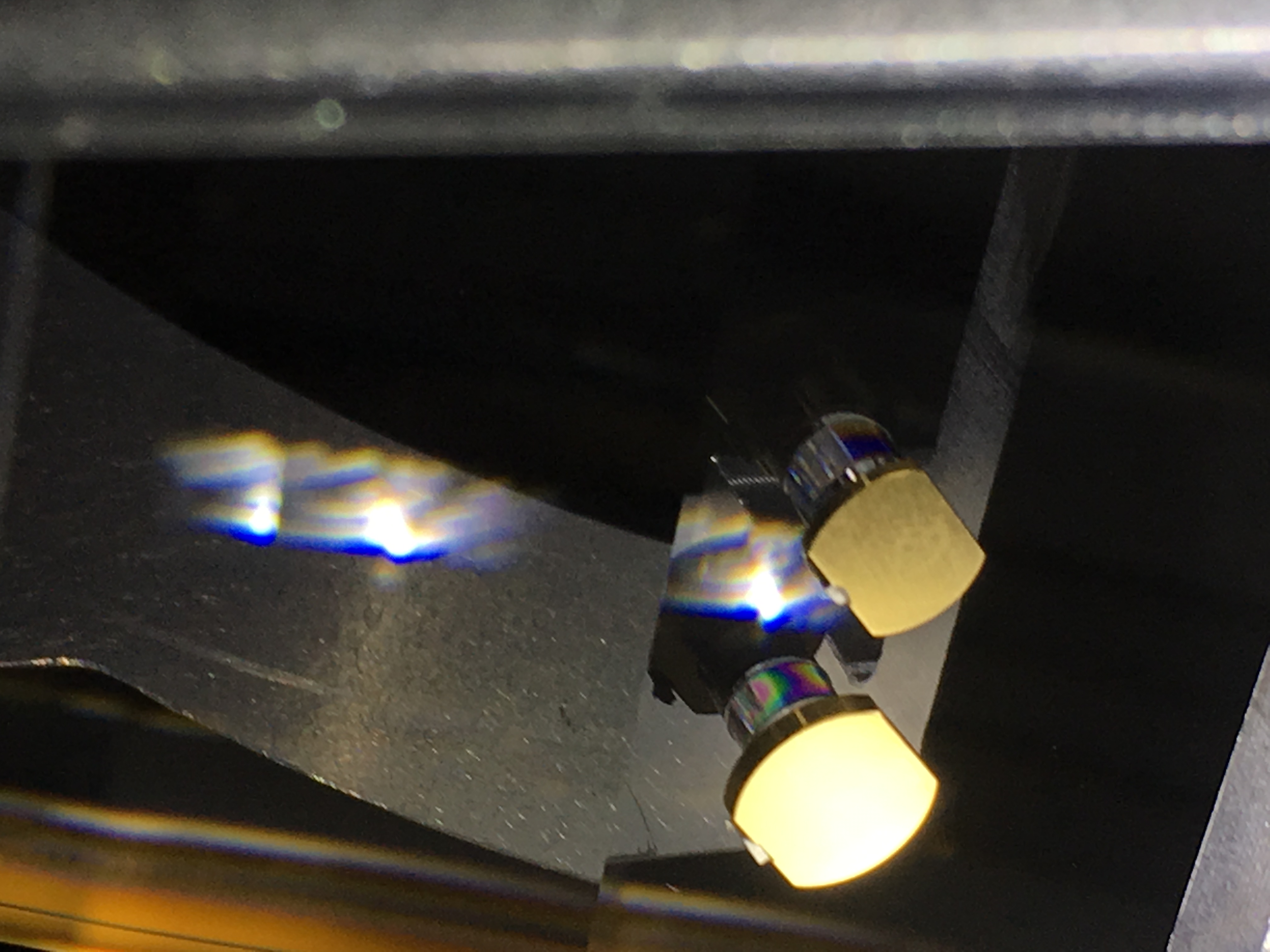
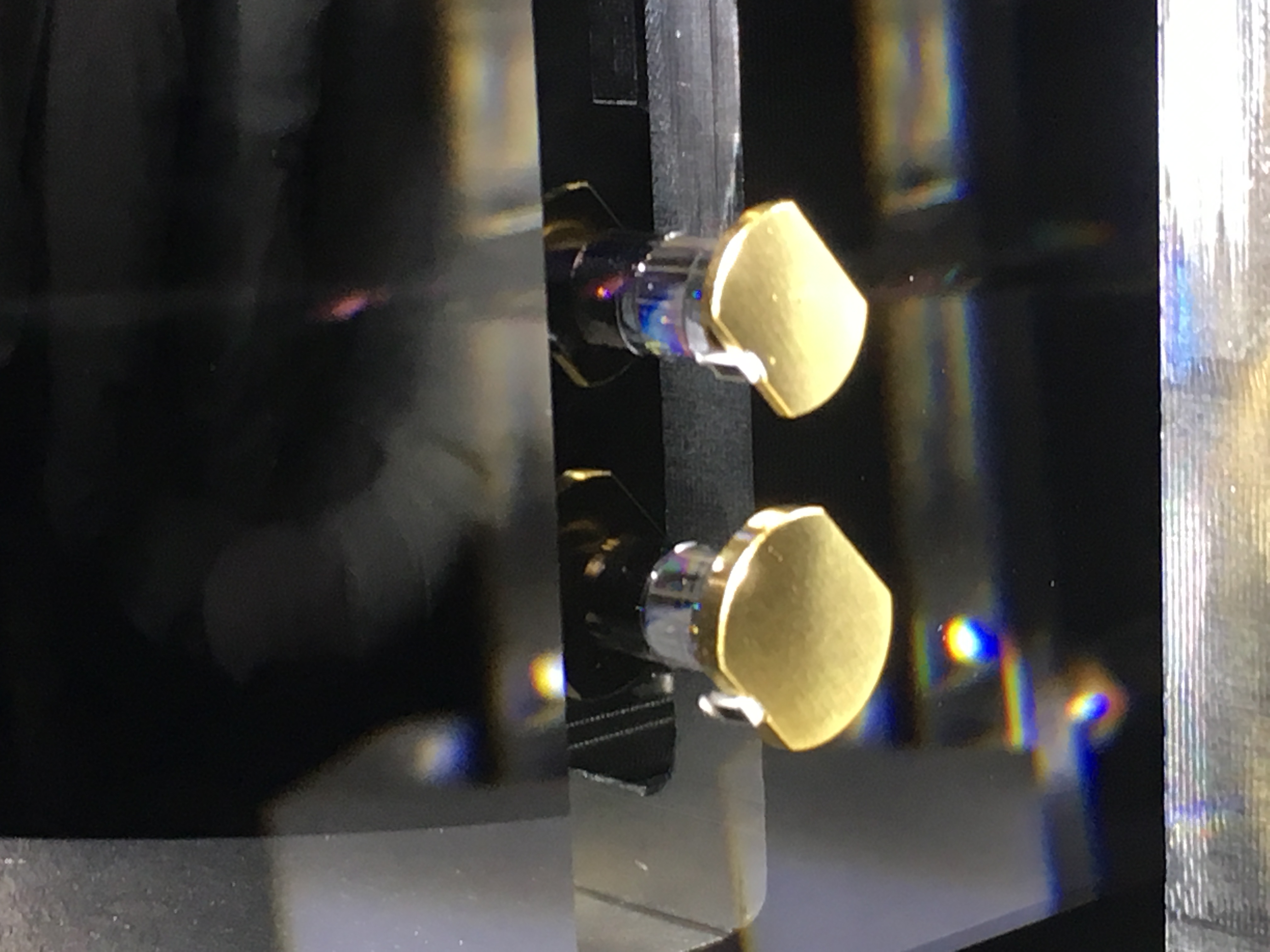
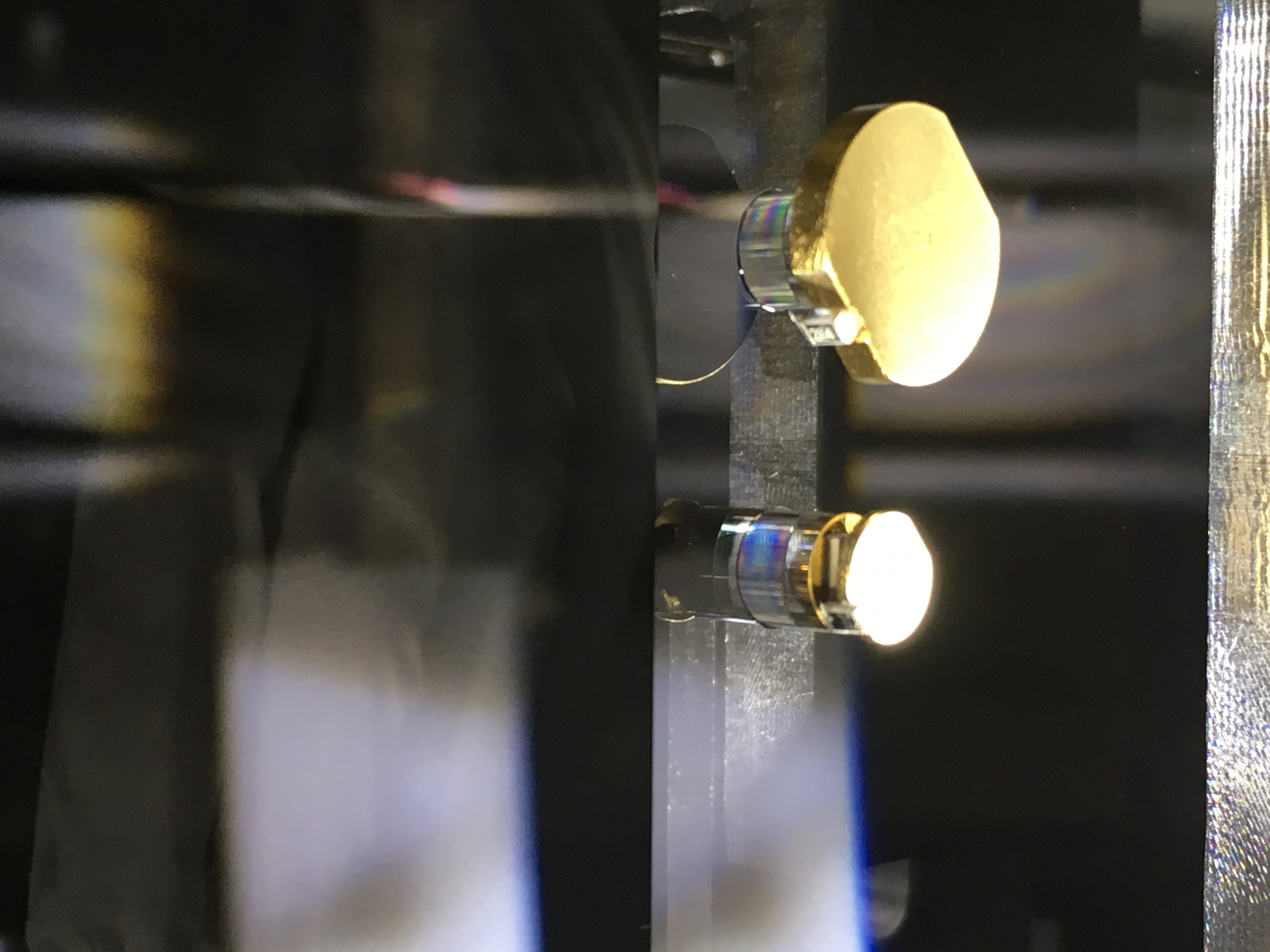
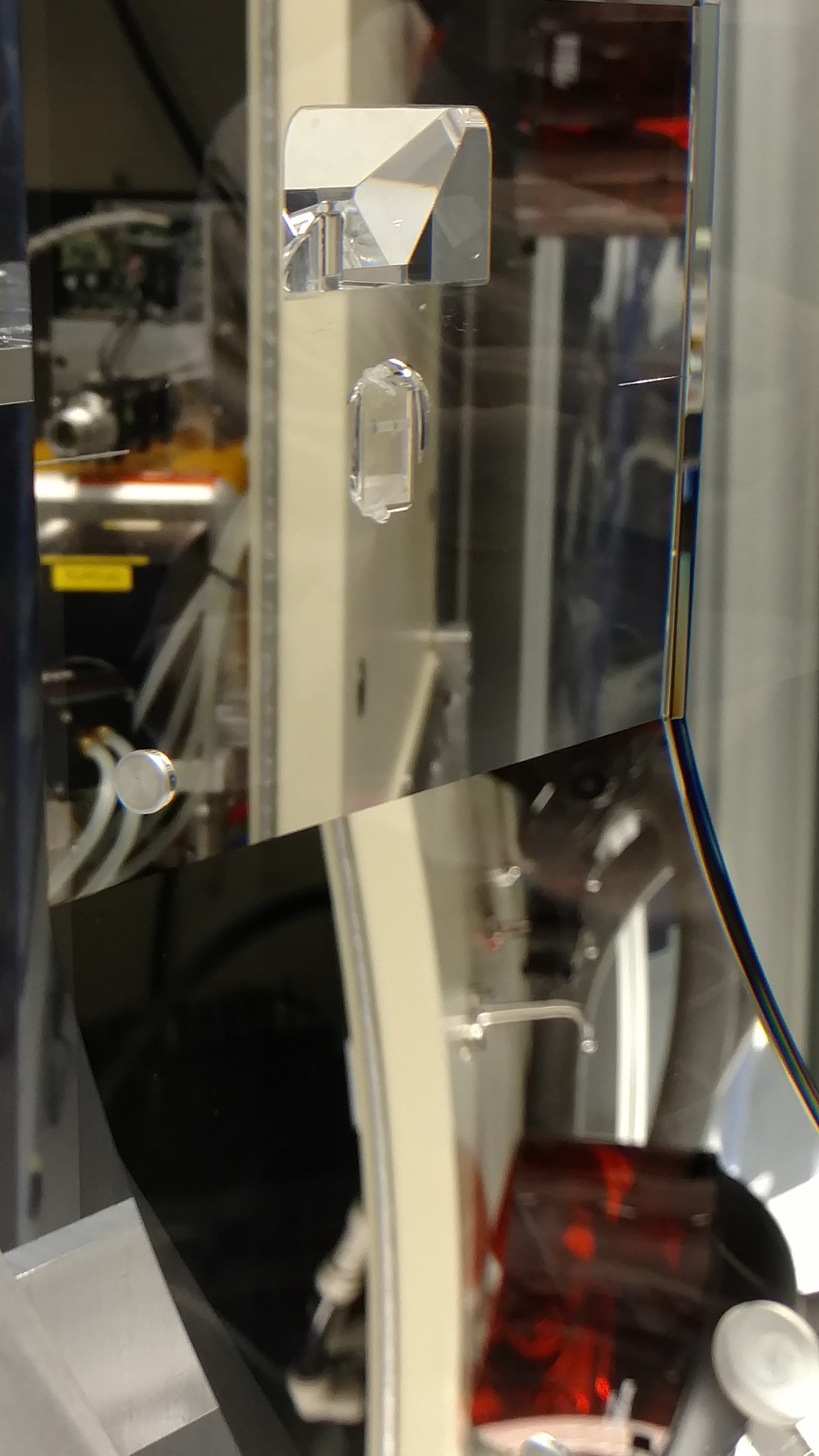
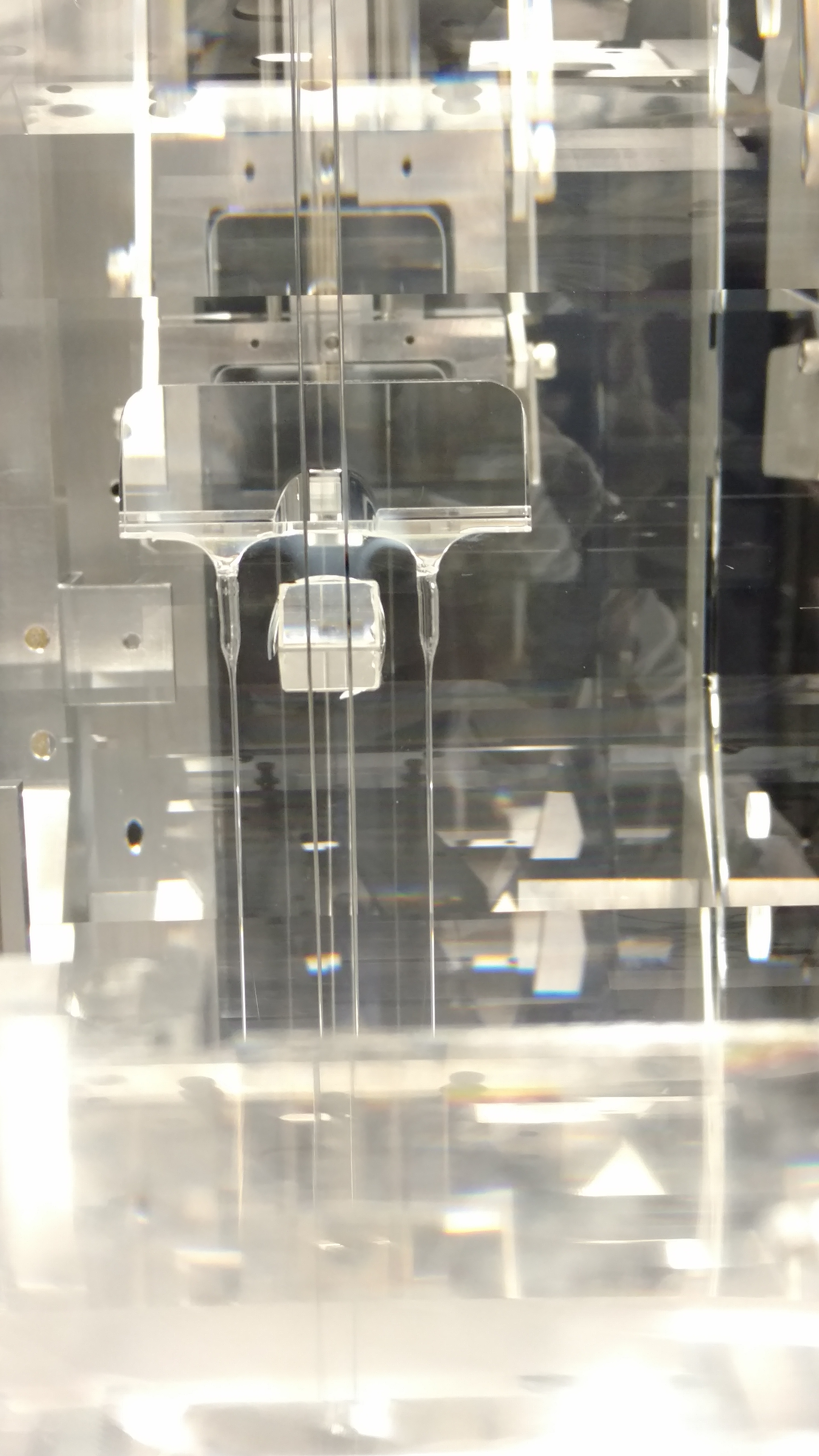
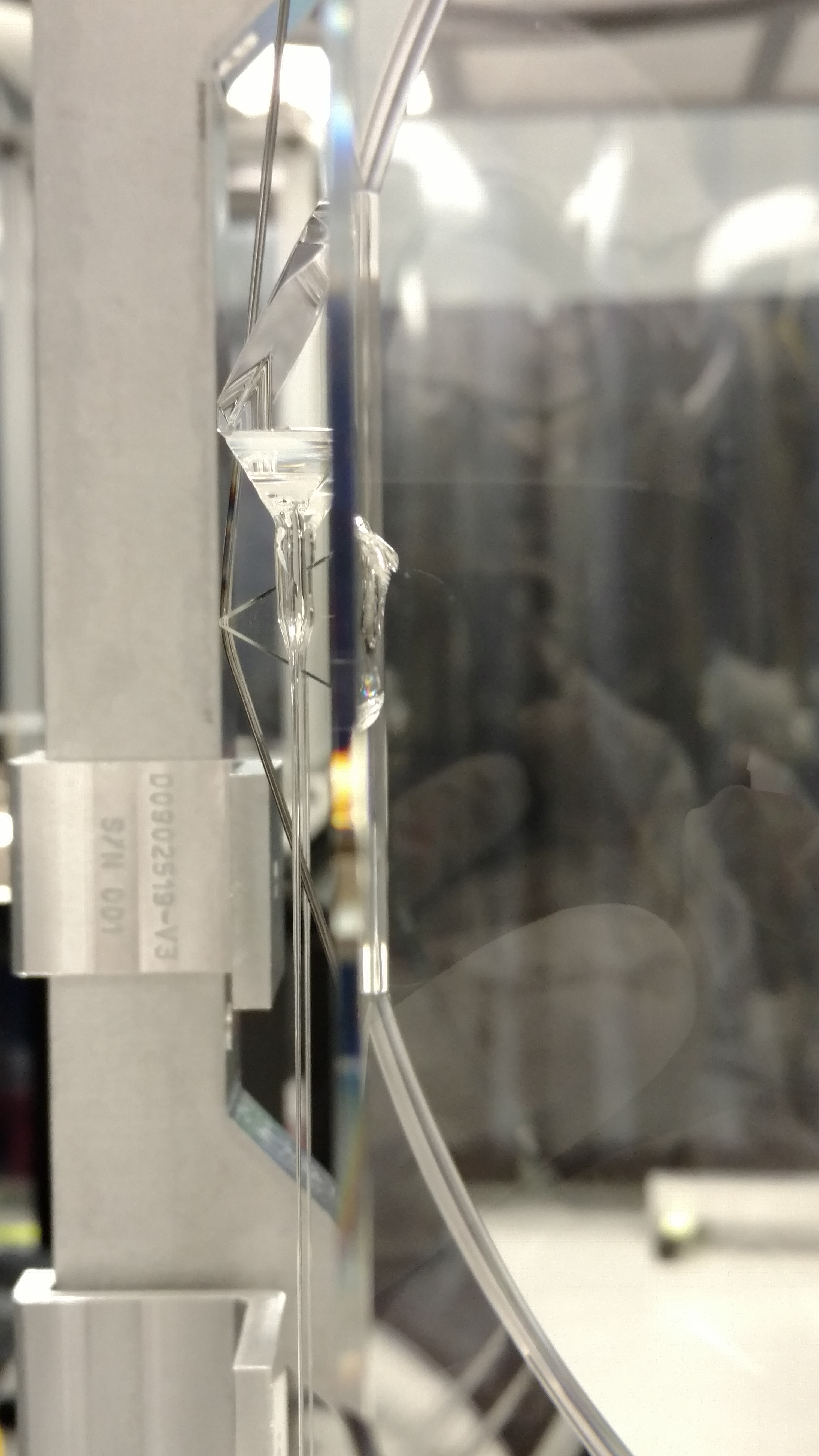
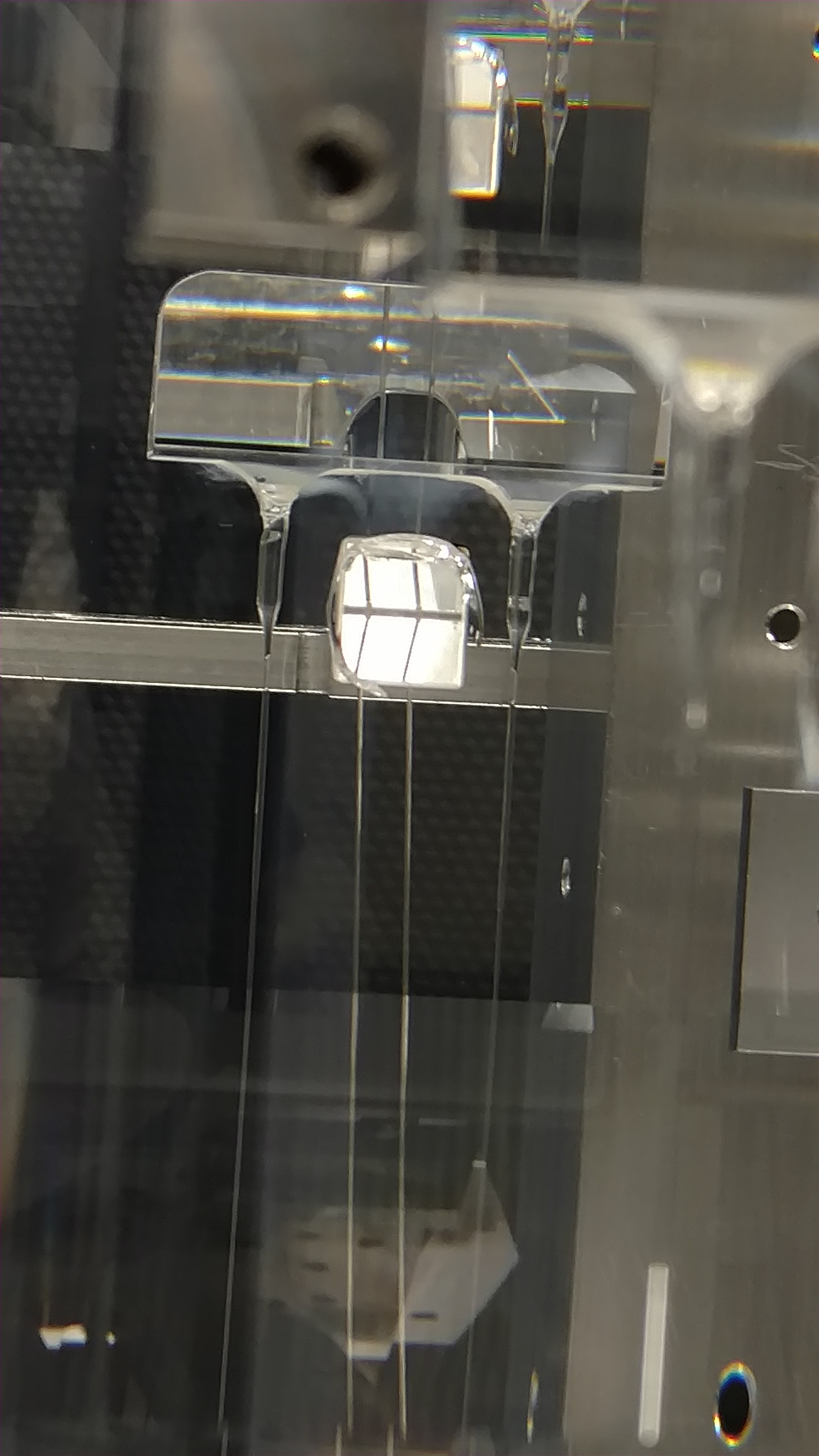
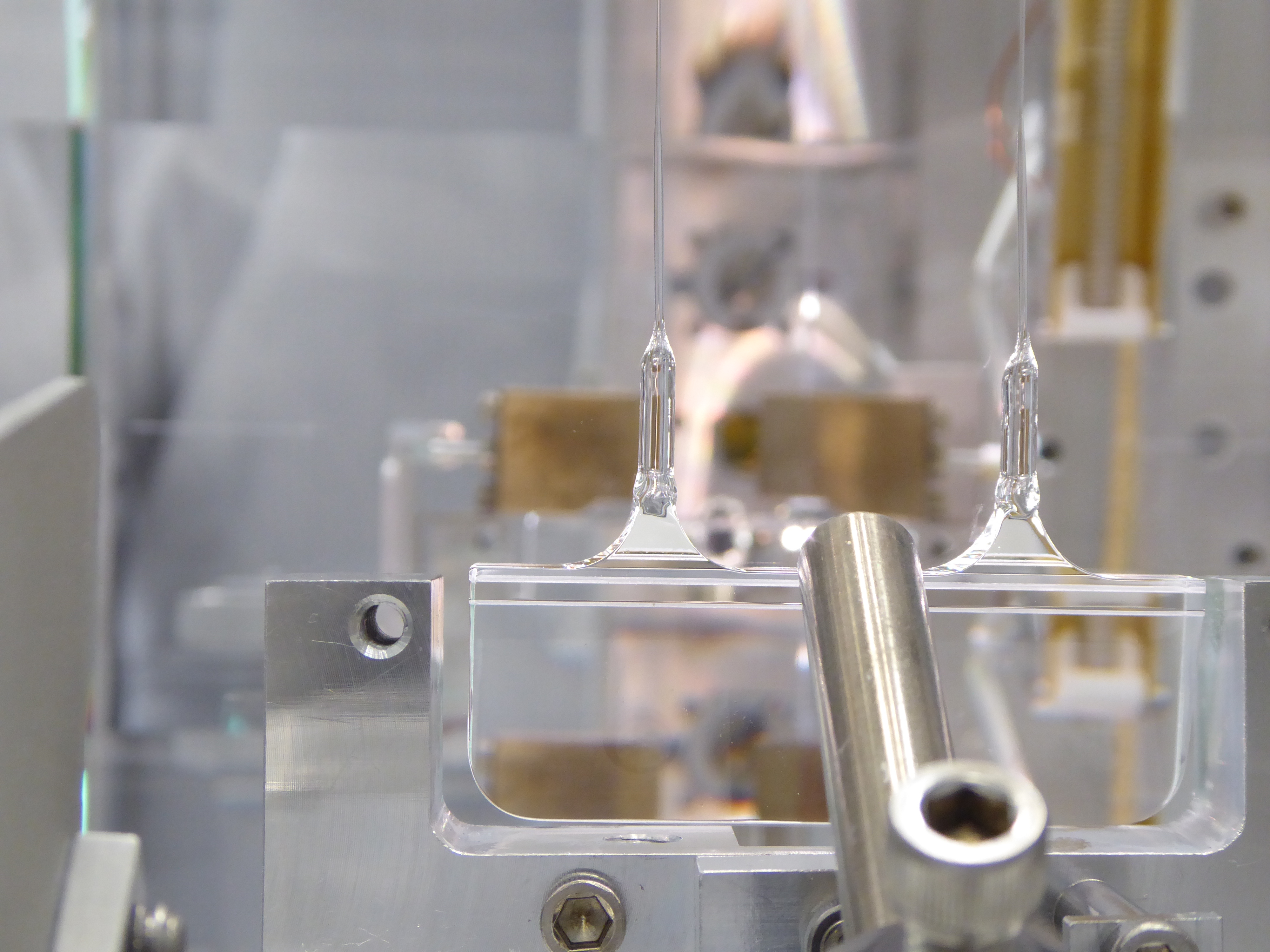
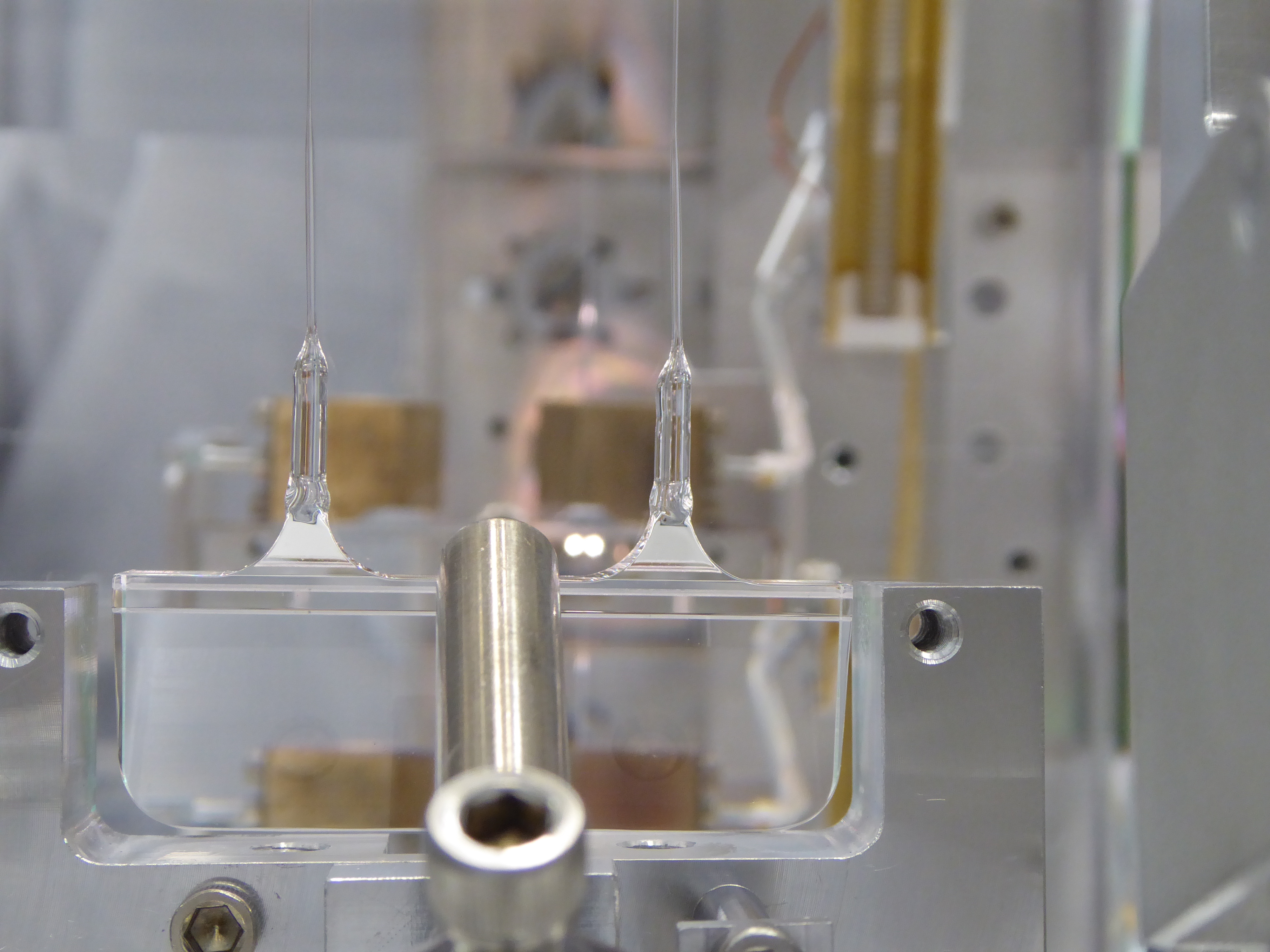
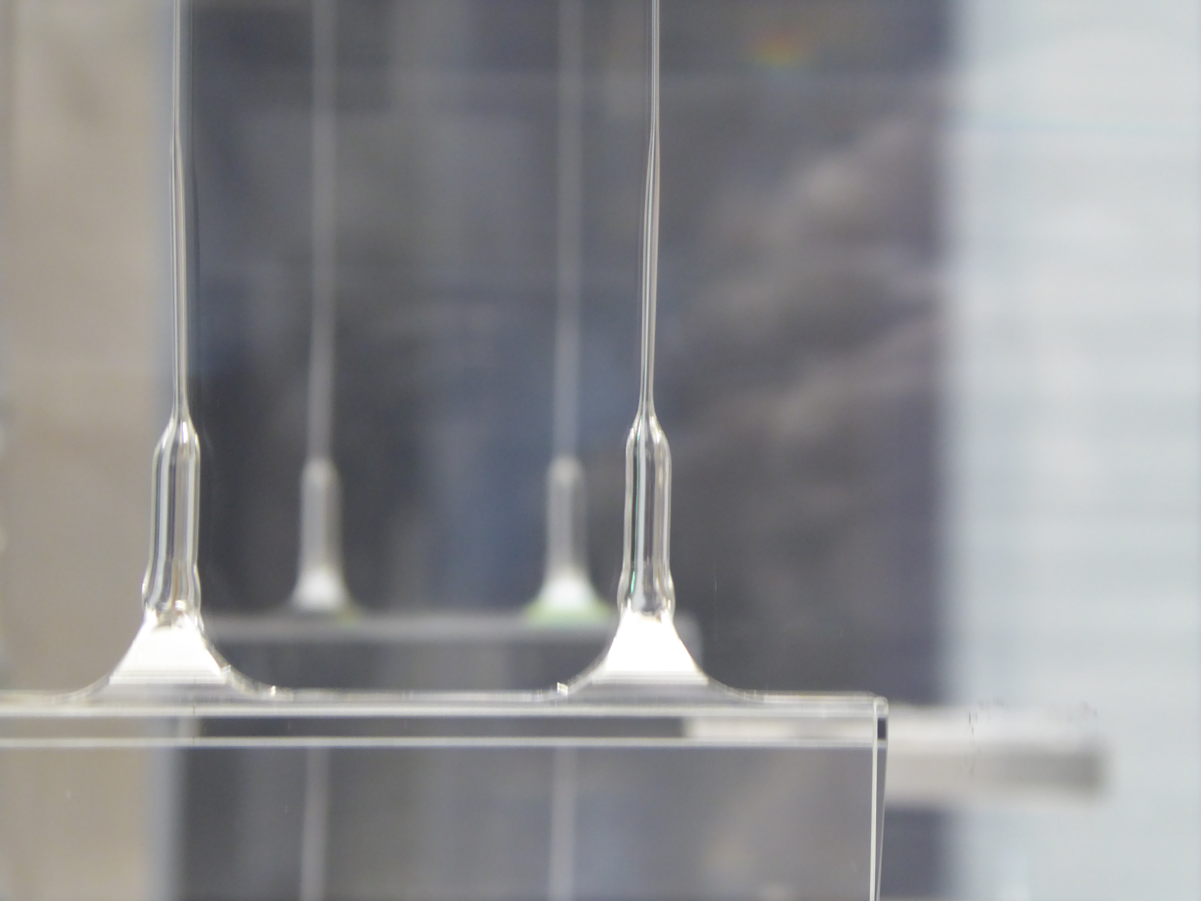
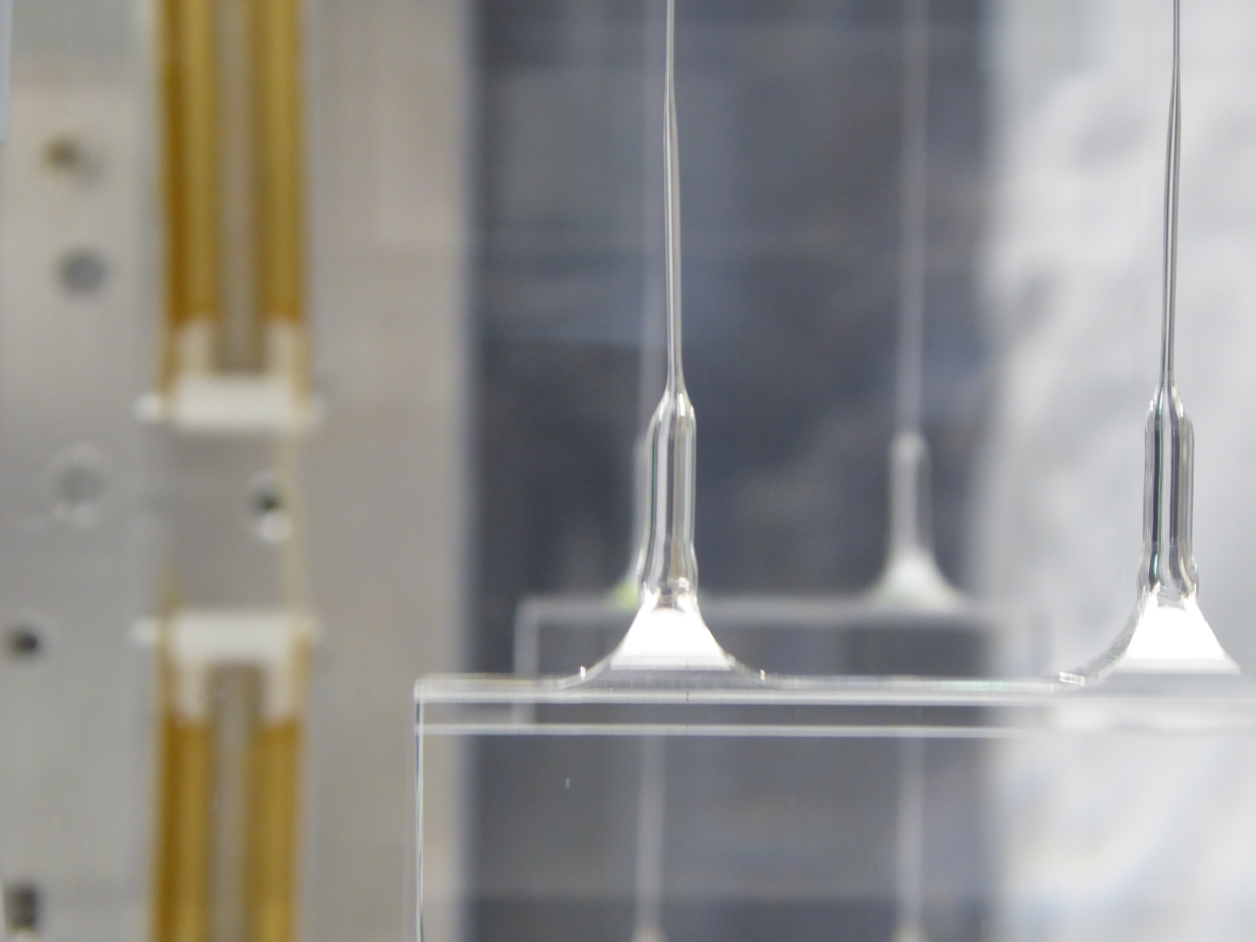
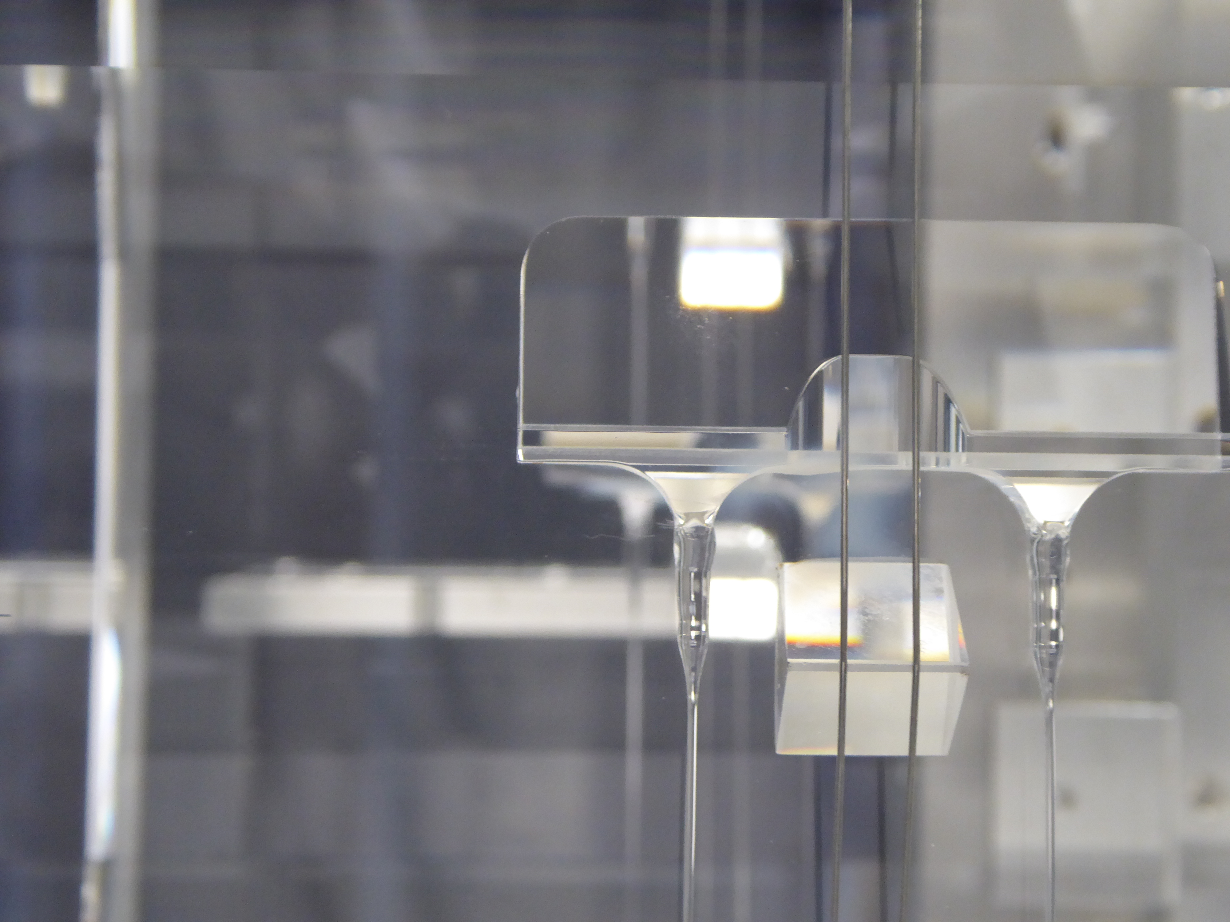
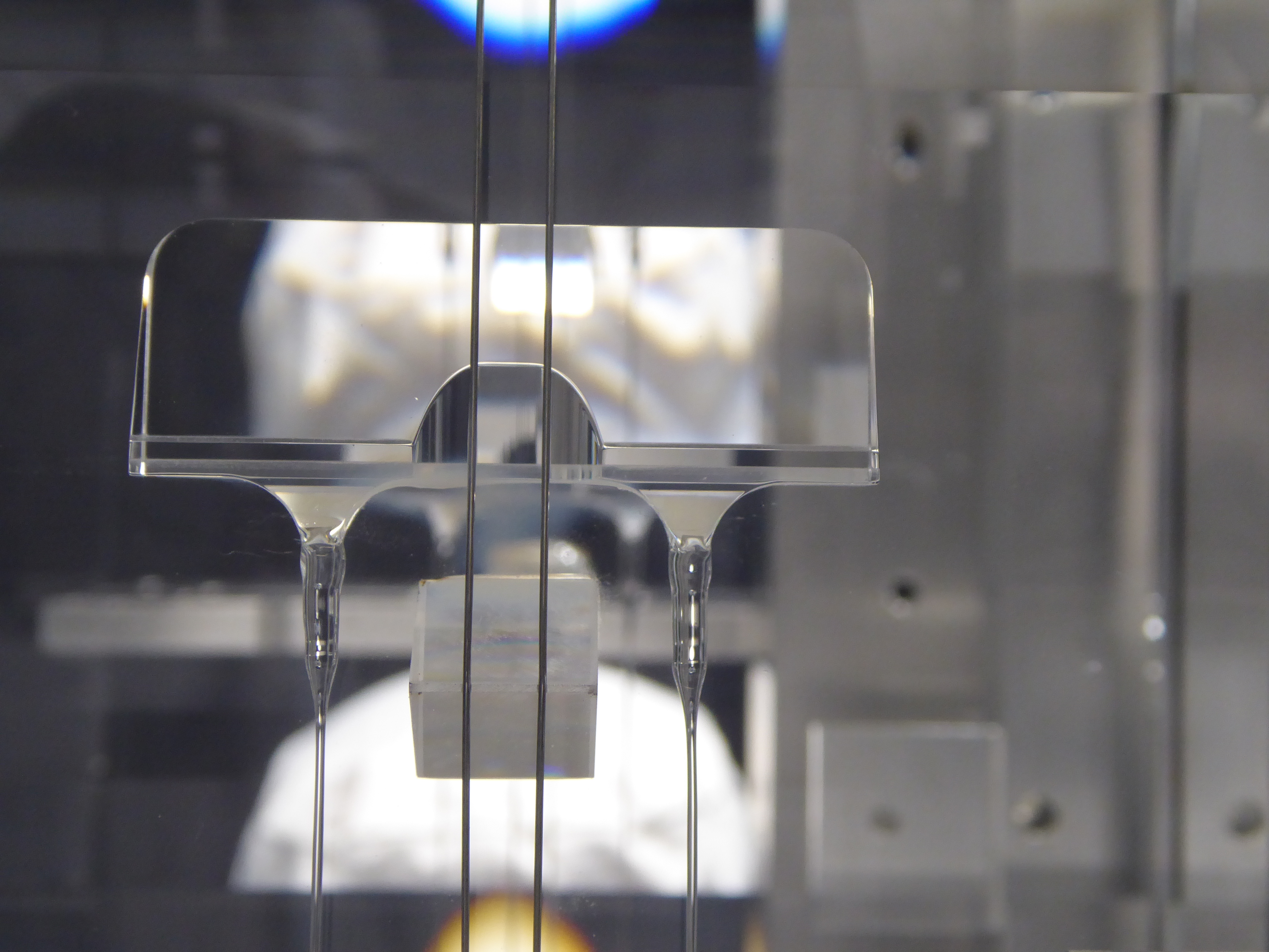
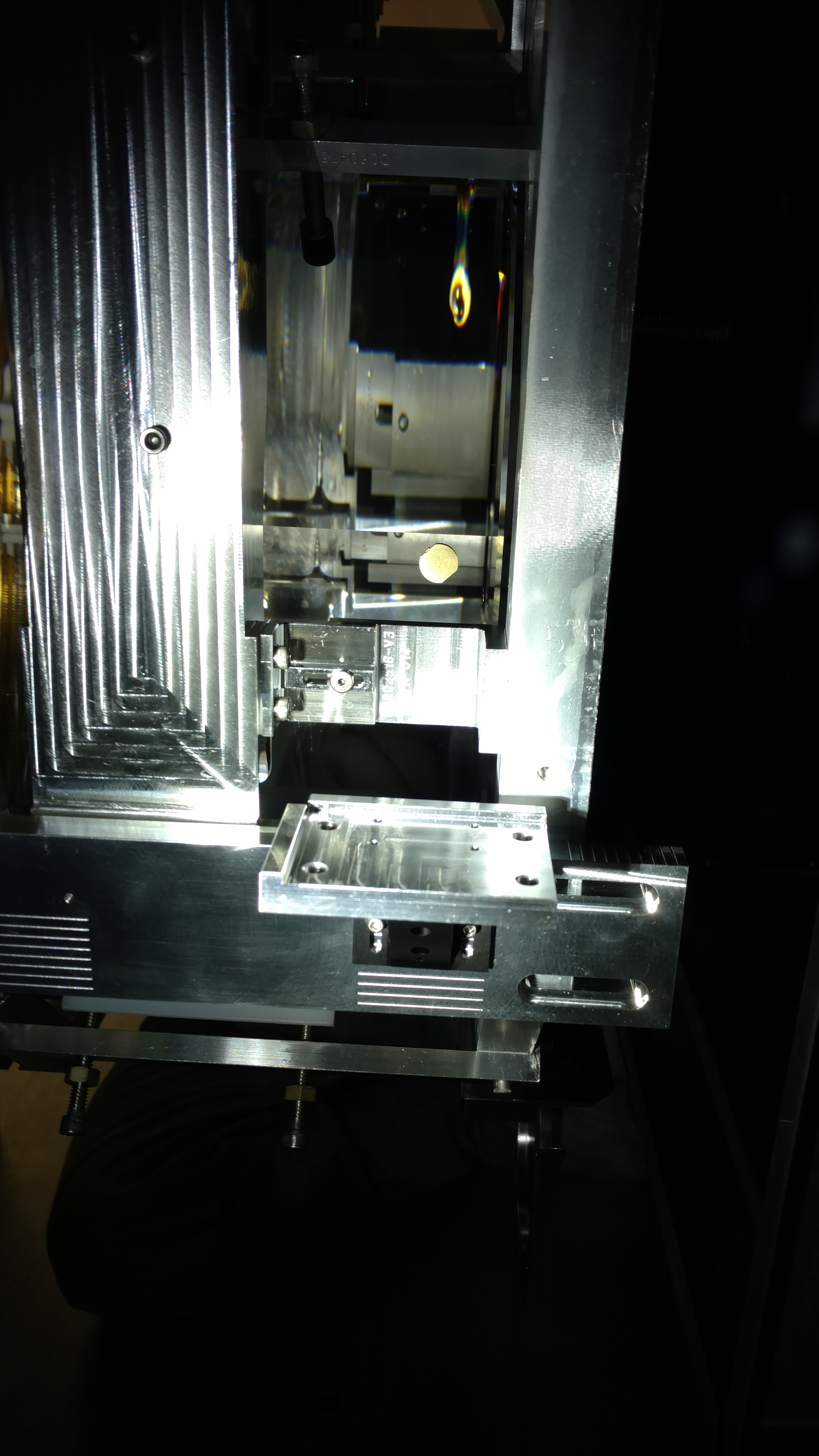
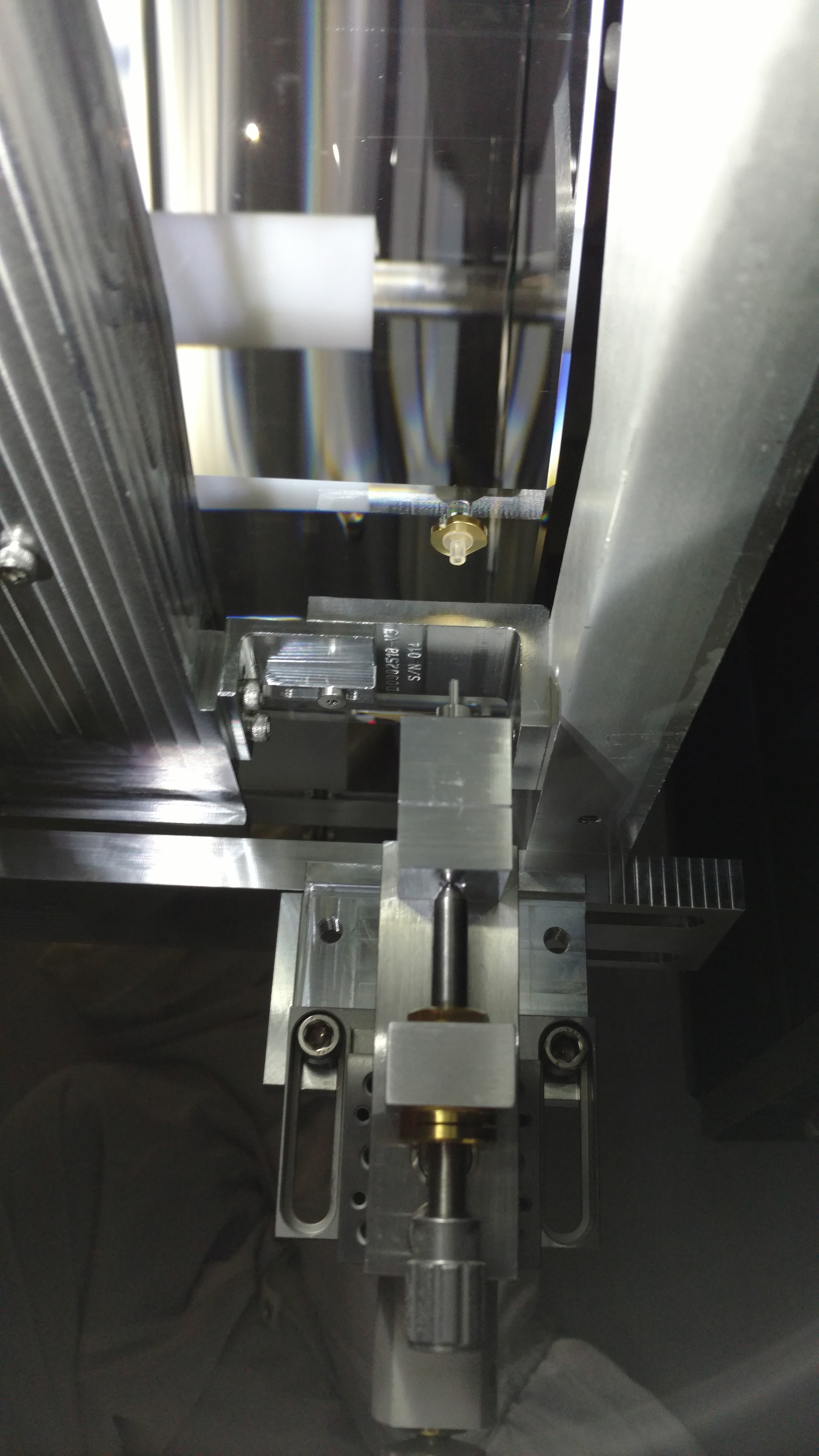
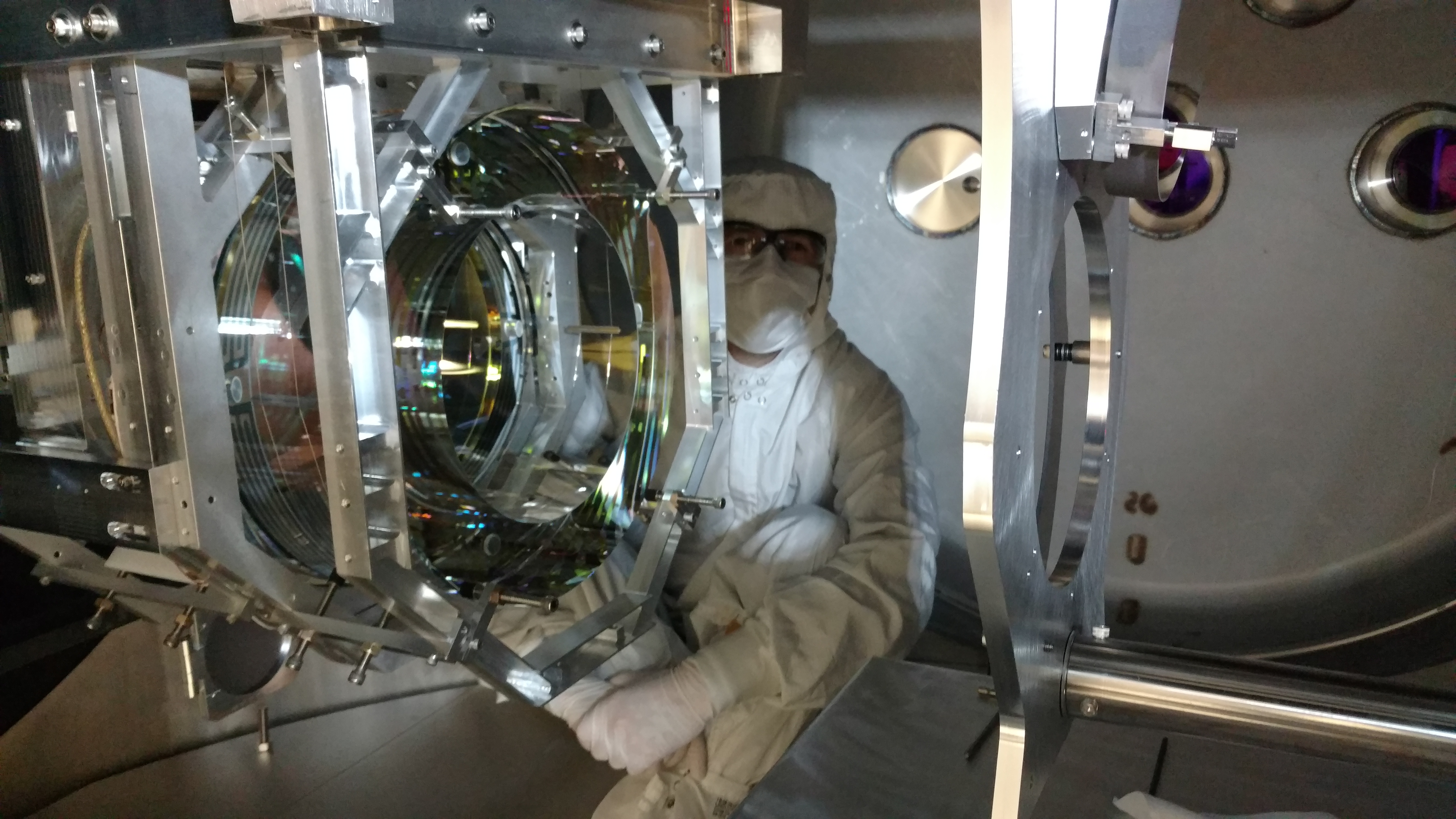
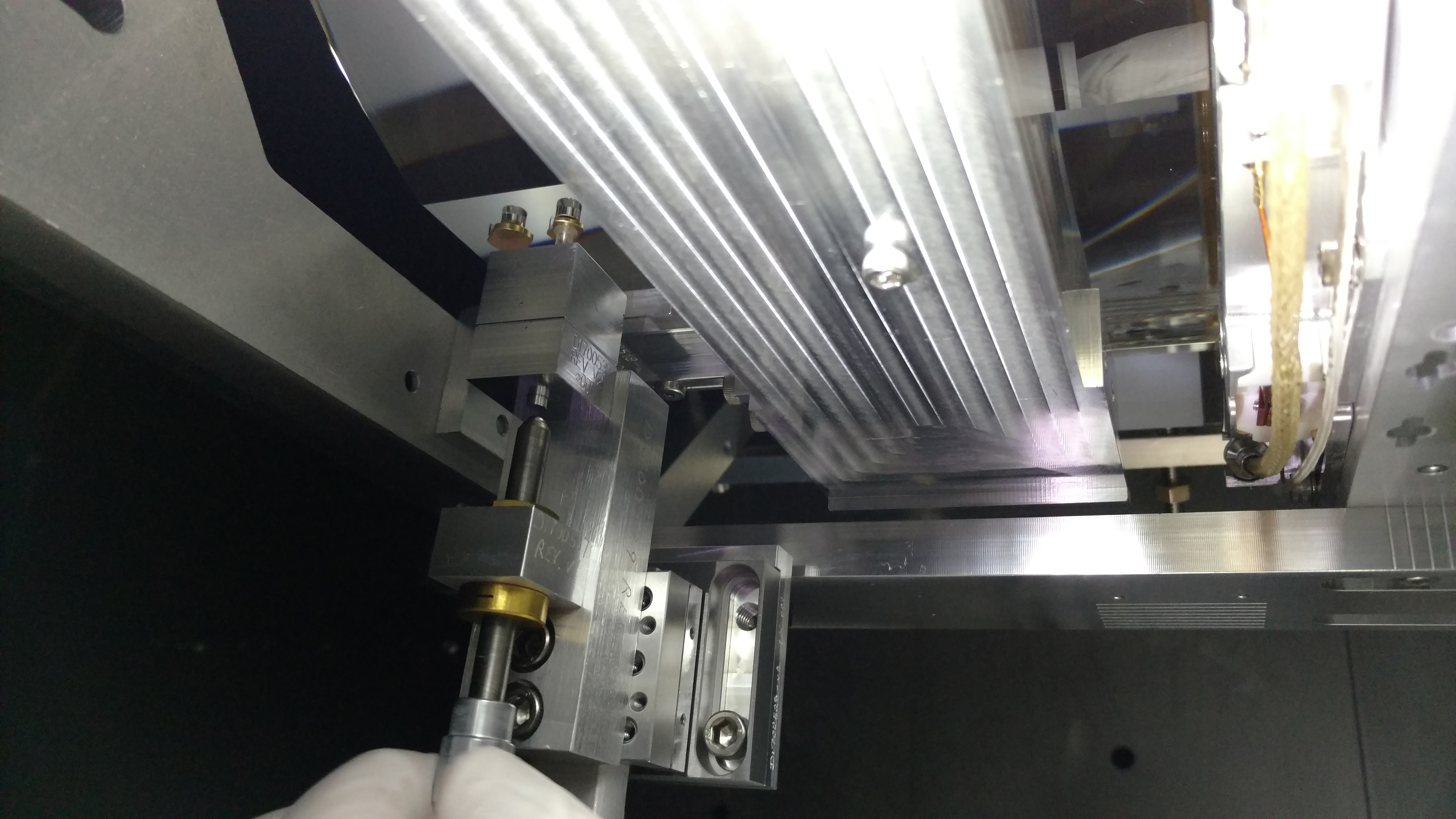
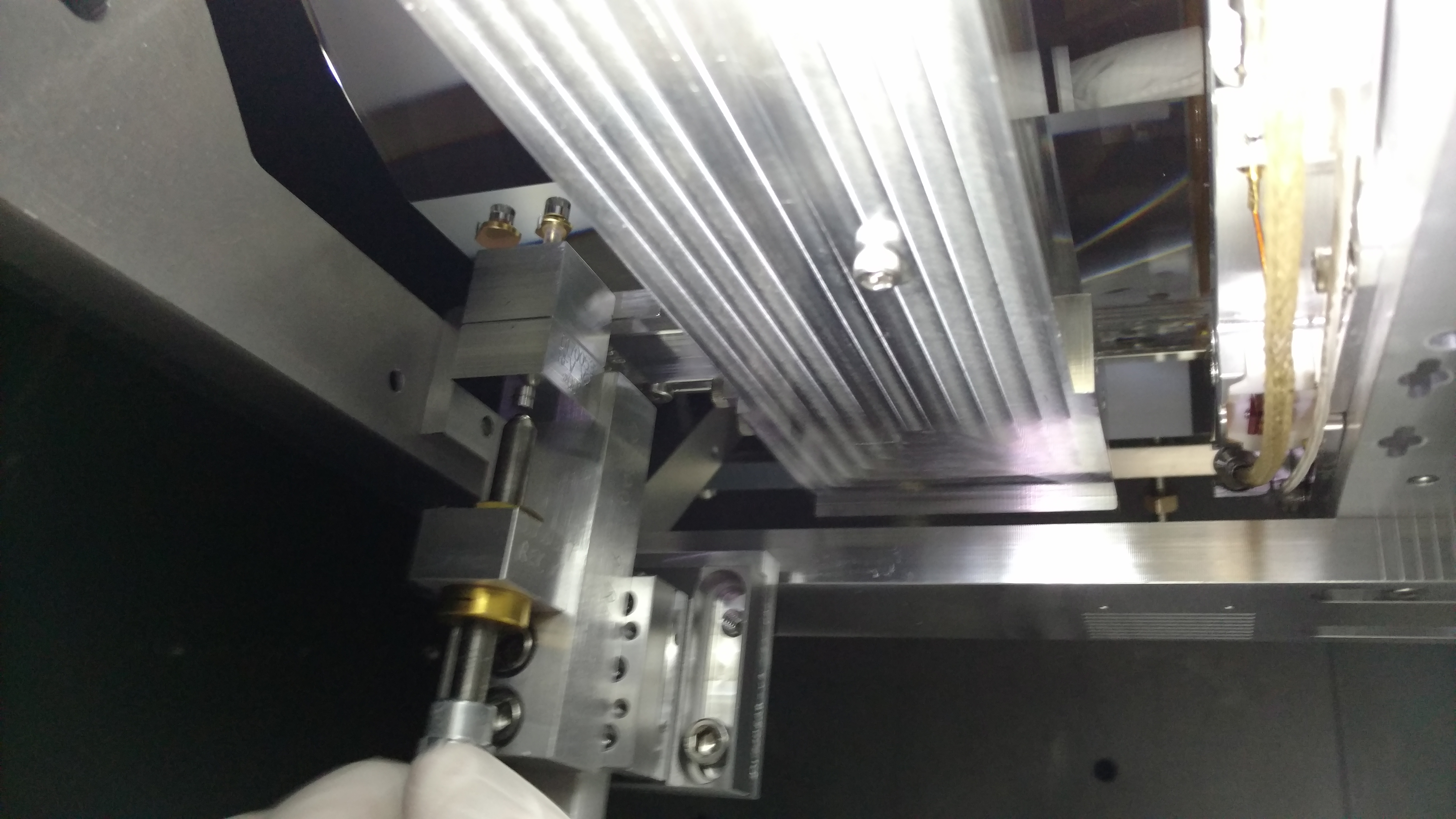
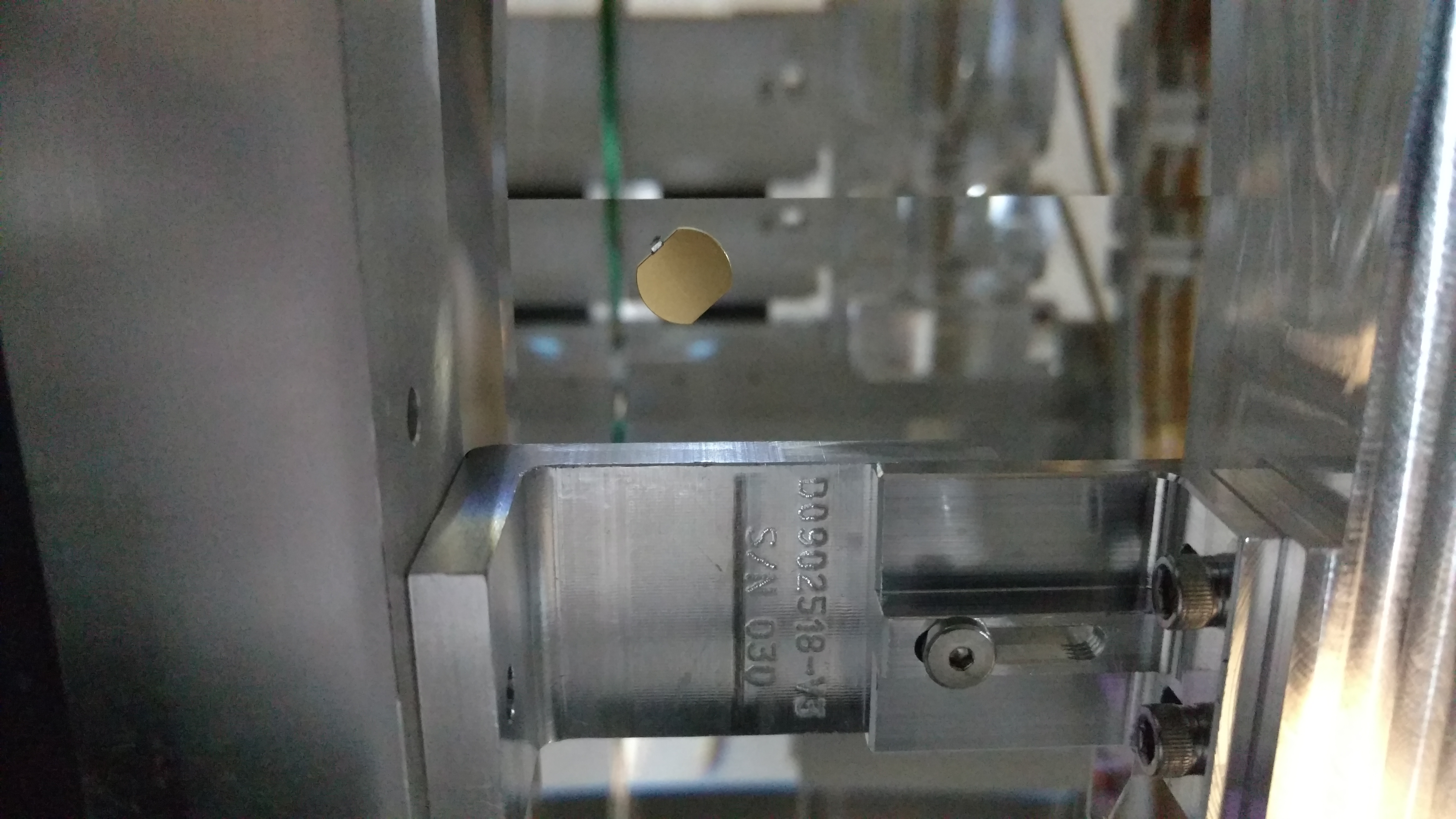
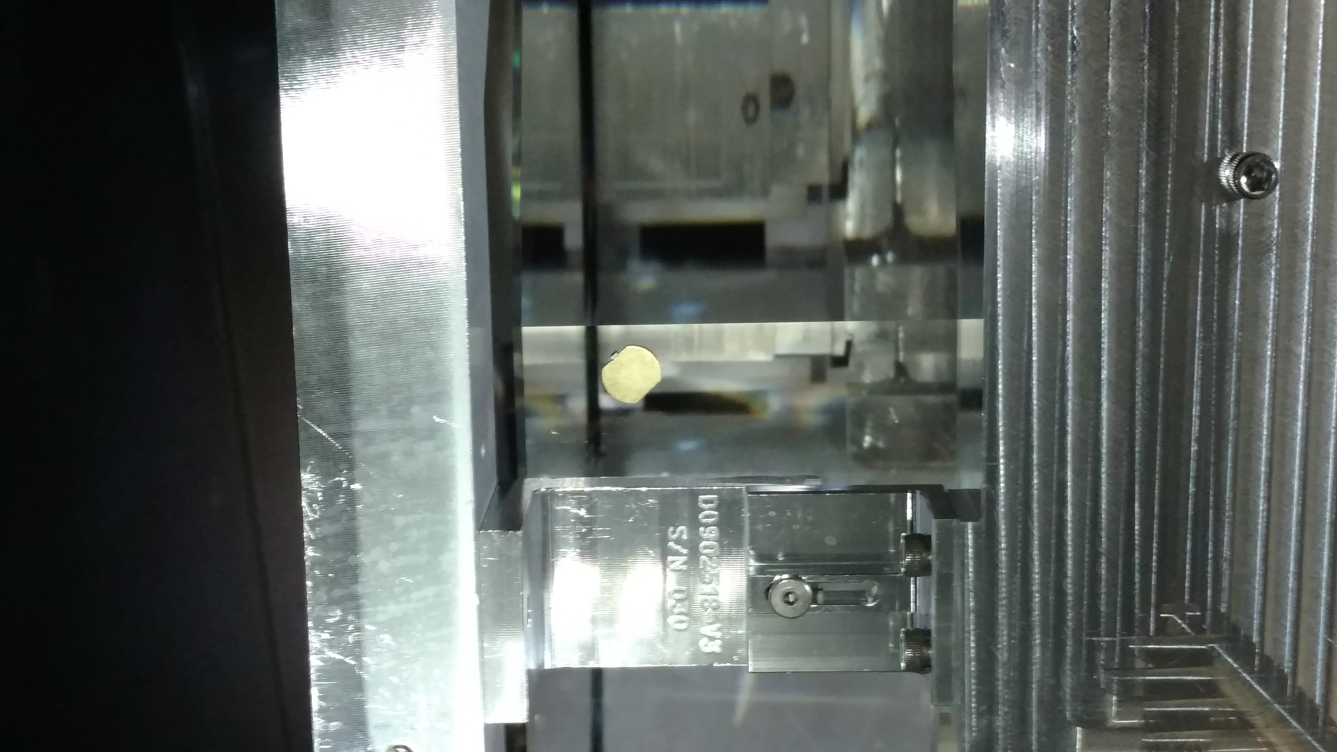
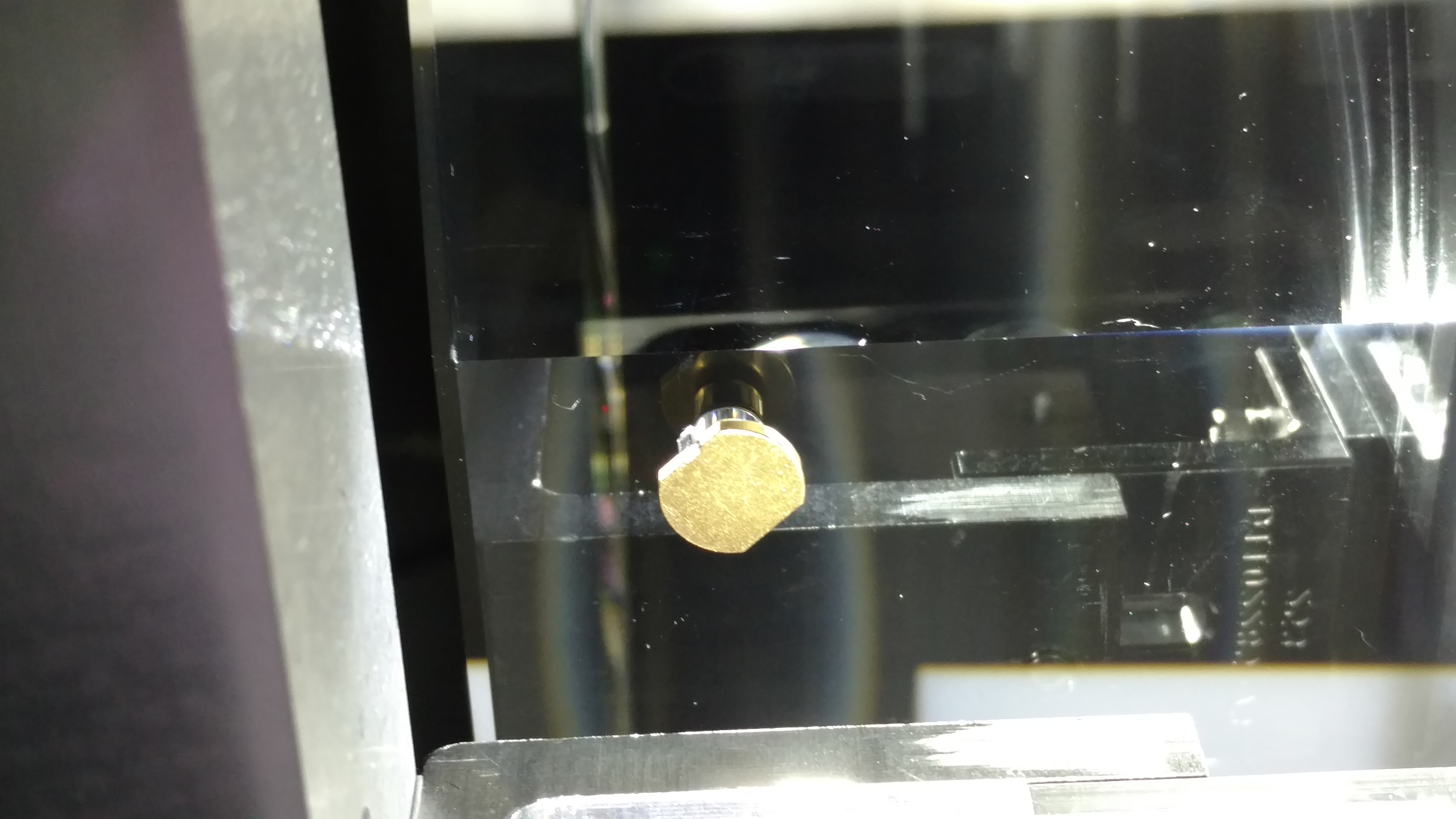
Pcal baffles and shields at End-Y; swap of button-head screws
JimW, RickS
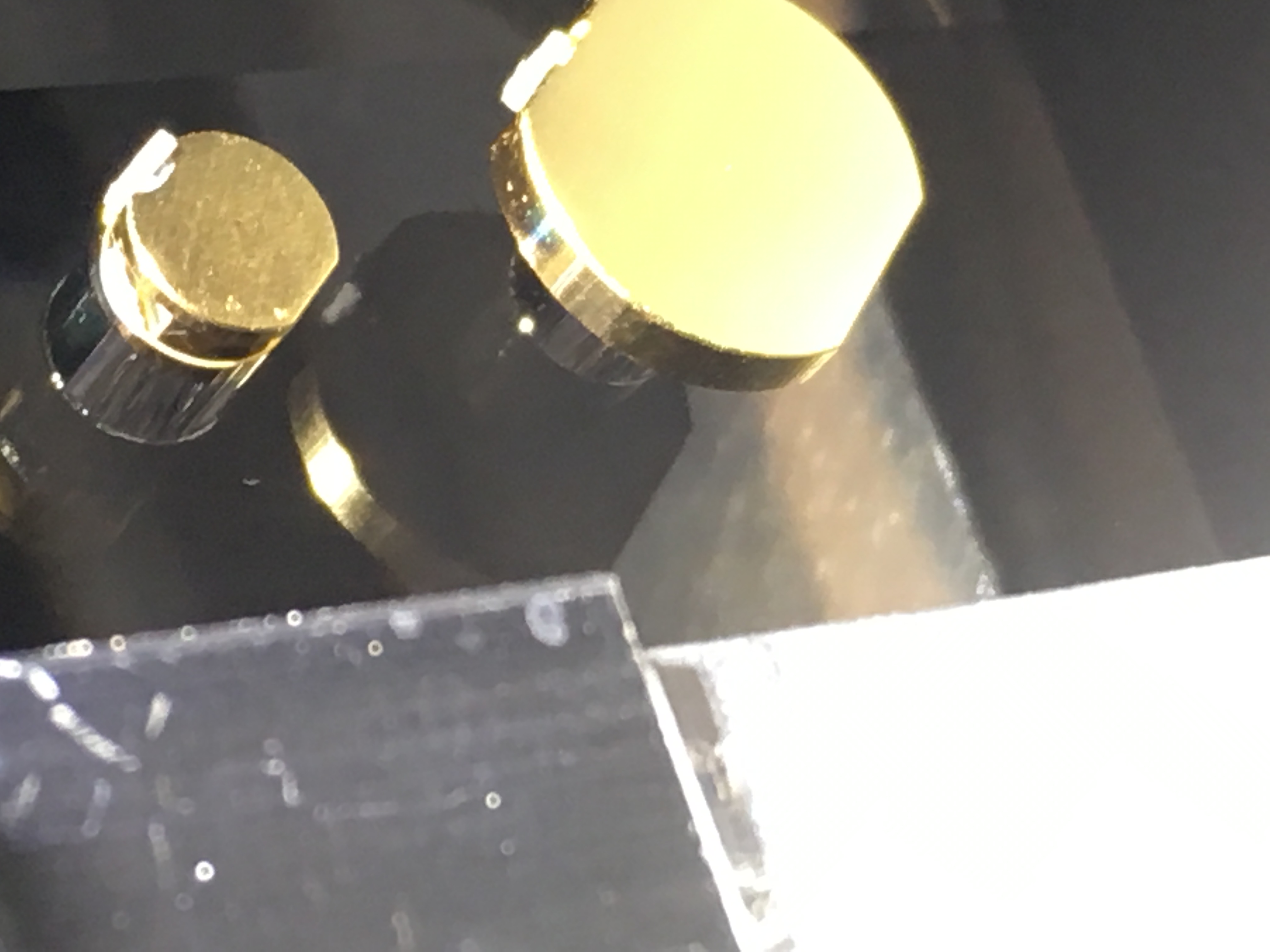
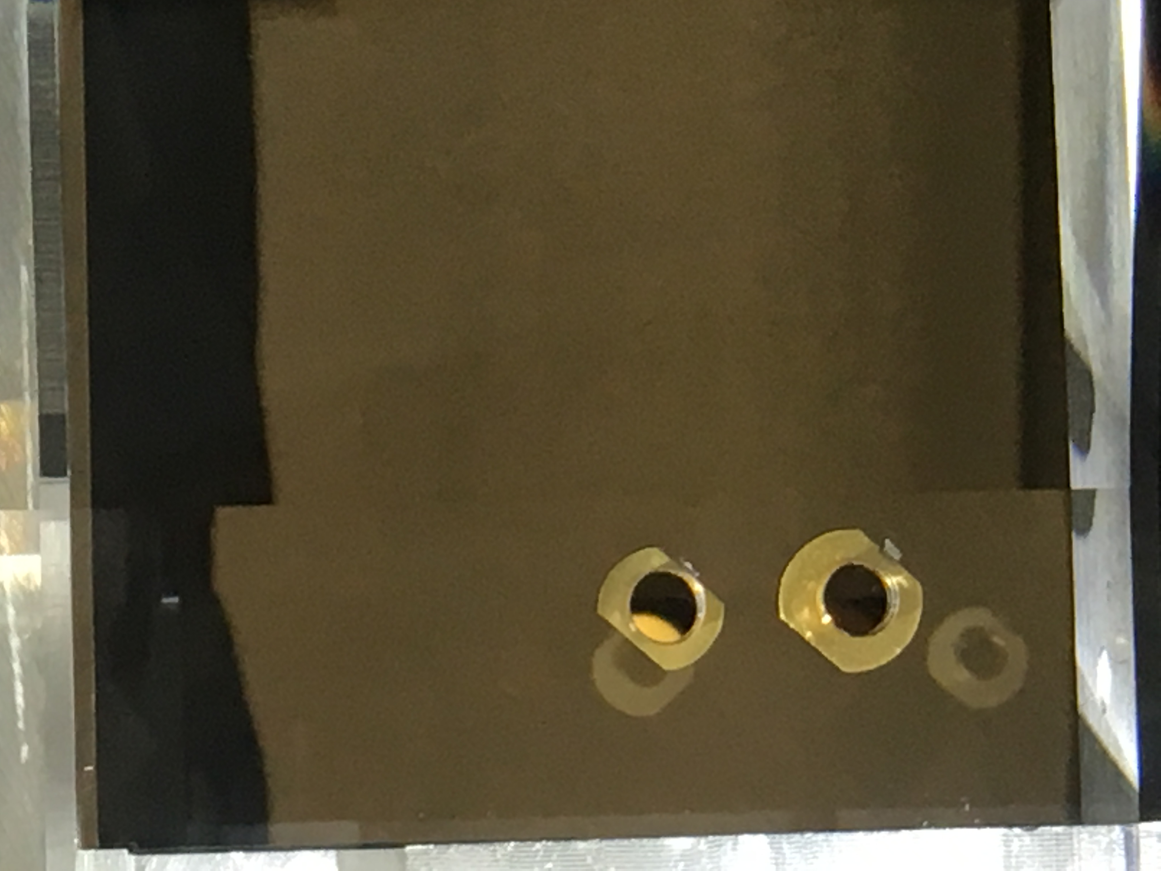
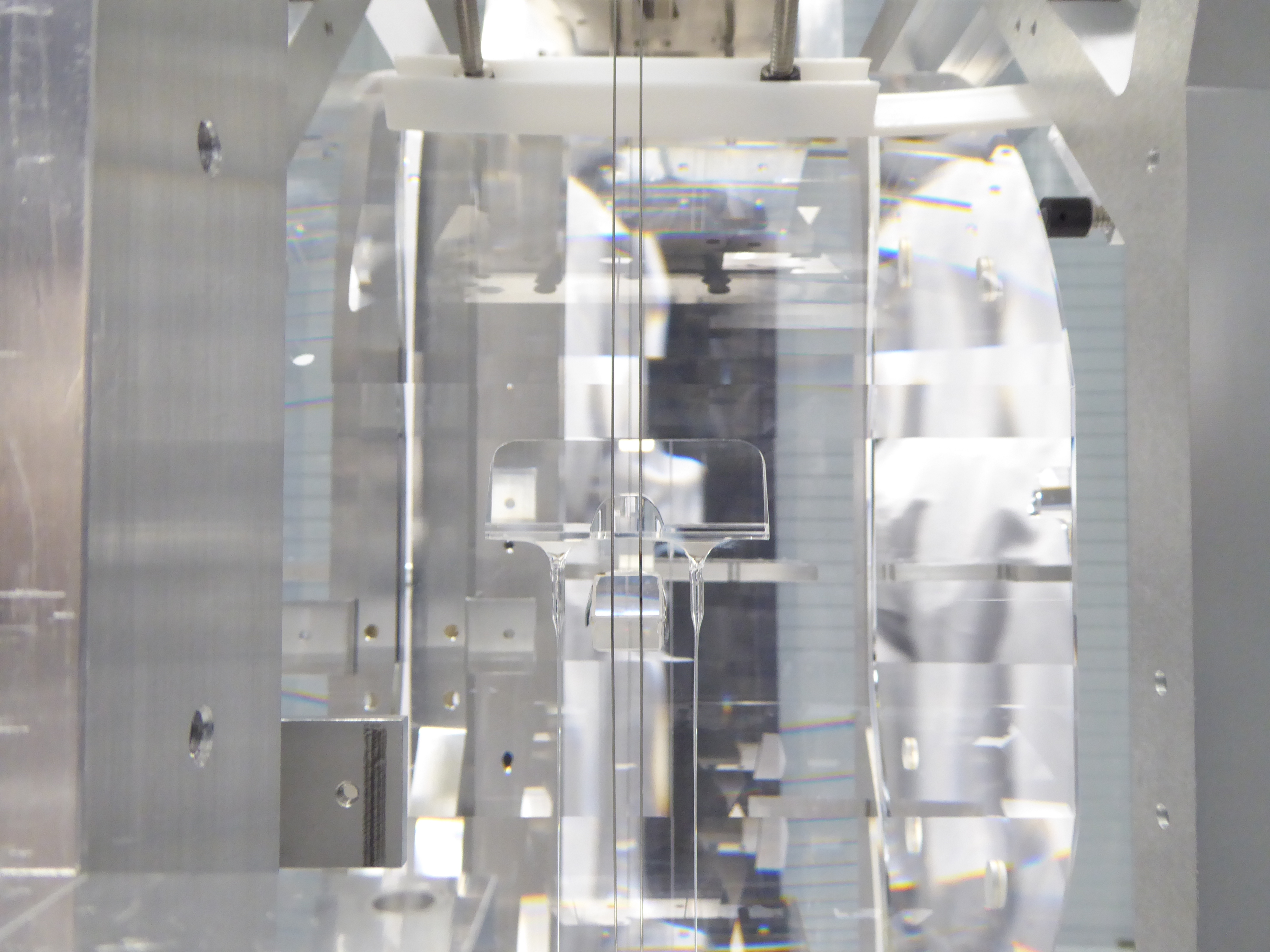
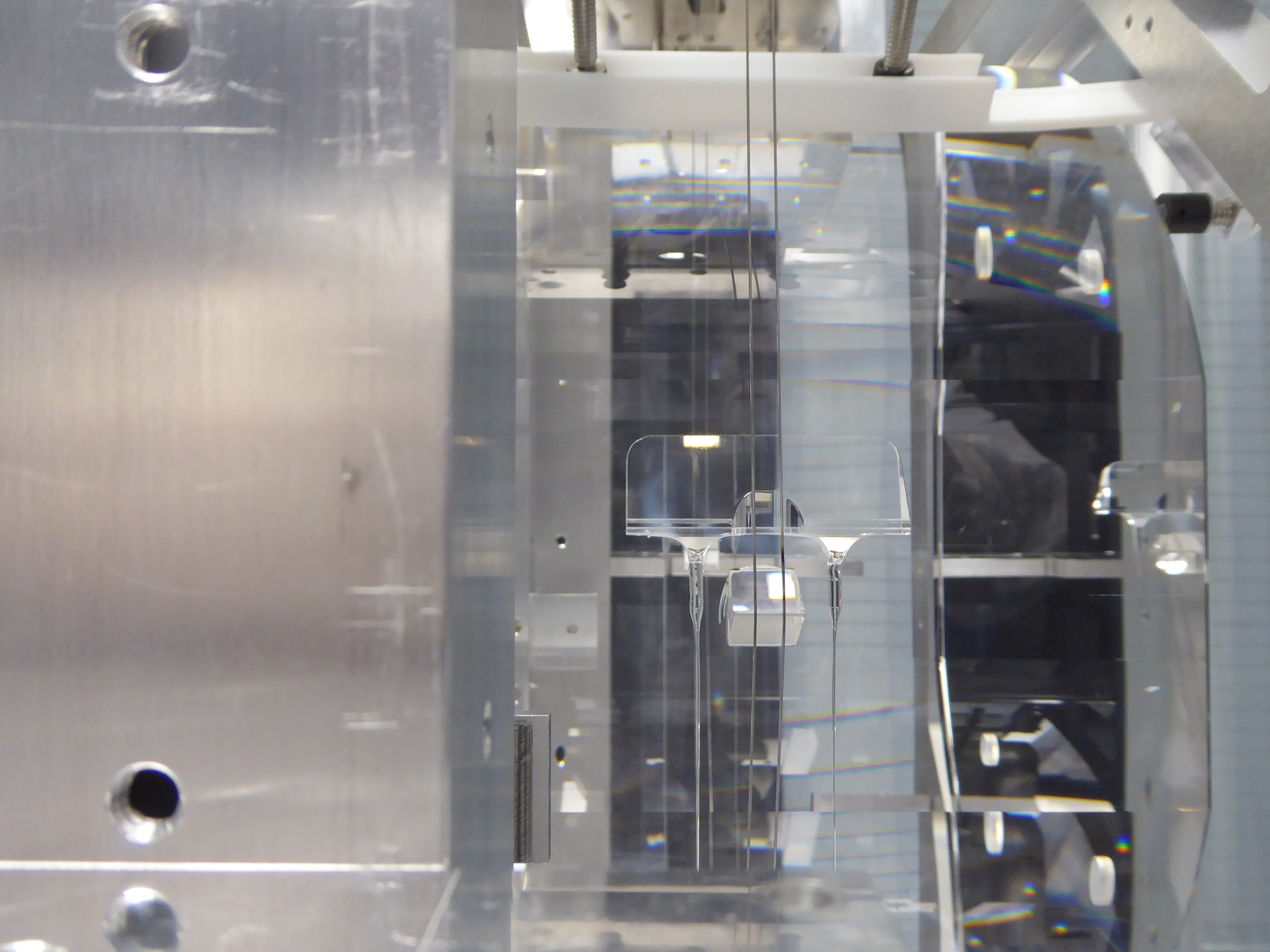
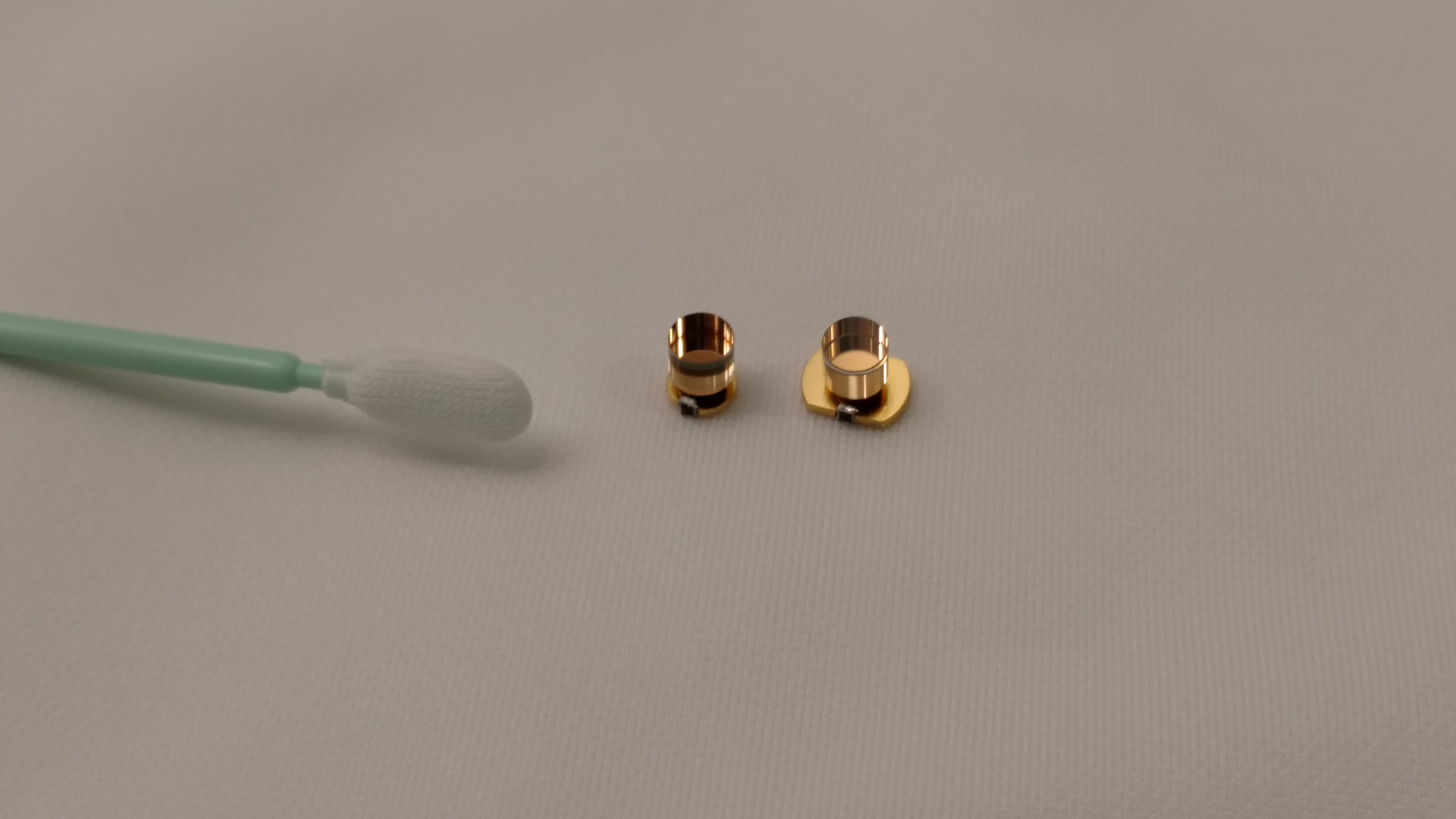
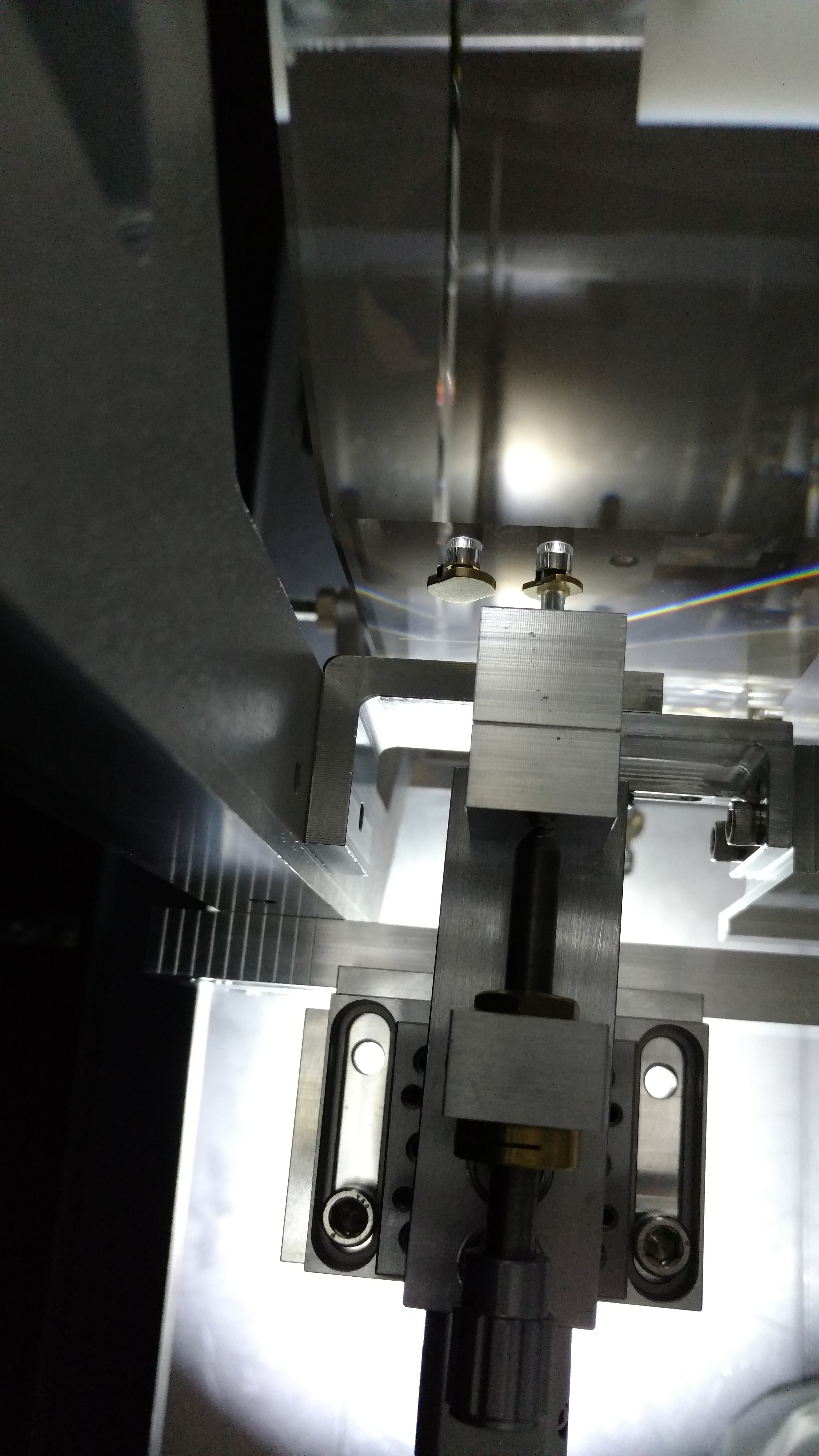
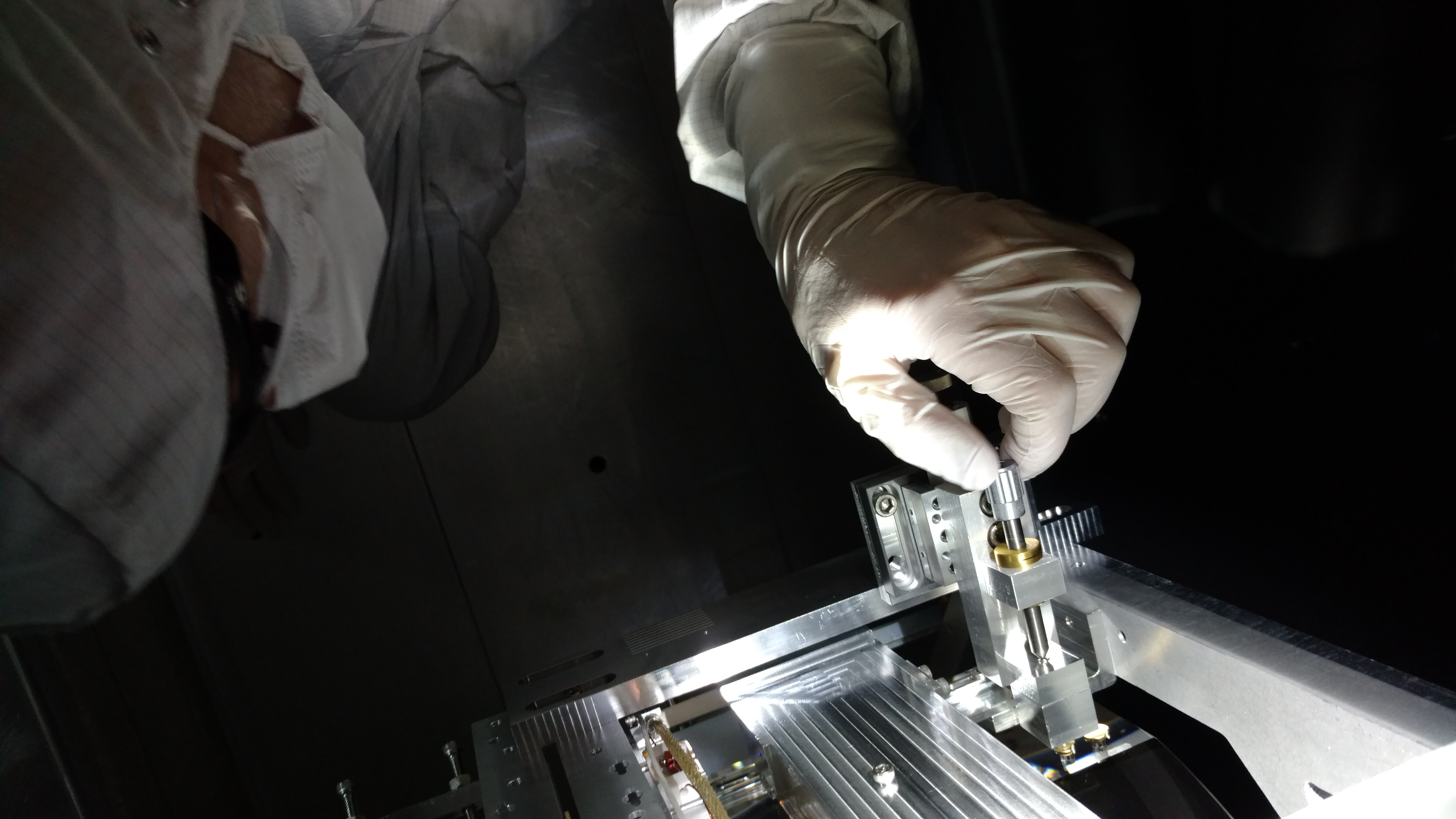
Last Friday, we swapped out the 48 electro-polished 1/4"-20 button-head screws screws that attach the "barrel" baffles for screws that had been coated to reduce reflectivity. We also swapped out the washers for coated washers.
Note that the heads of the coated screws are deeply stamped with letters and numbers, while the electro-polished units are smooth.