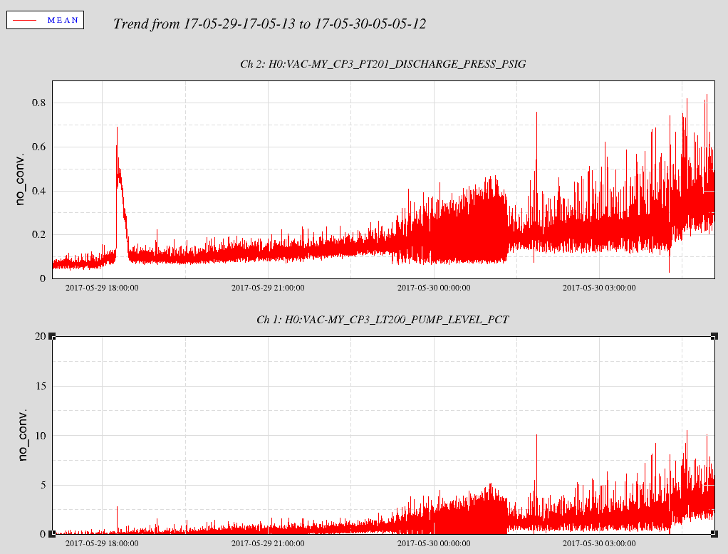
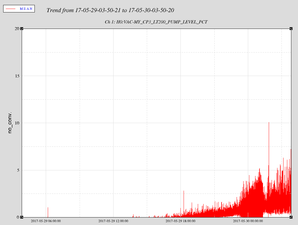
The ice blockage has opened up on CP3! See last VE log entry. Kyle and I connected full T-sized GN2 bottle with acrylic rotameter (5 LPM range) to the sensing line and started out flowing 1 LPM. The flow held and we noticed fluctuations in the exhaust pressure (0.2-0.4 psi). Then I got antsy and bumped flow up to 1.5 LMP and it slowly increased to 2 LPM. The signal value (% full) is slowly growing! We saw exhaust pressures as high as 0.8 psi and signal value up to 10%. We are leaving it flow at 2 LPM overnight with shift-monitoring and -logging. Kyle will log odd hours and I will log even hours. We are being overly cautious about the not boiling CP3 dry overnight.
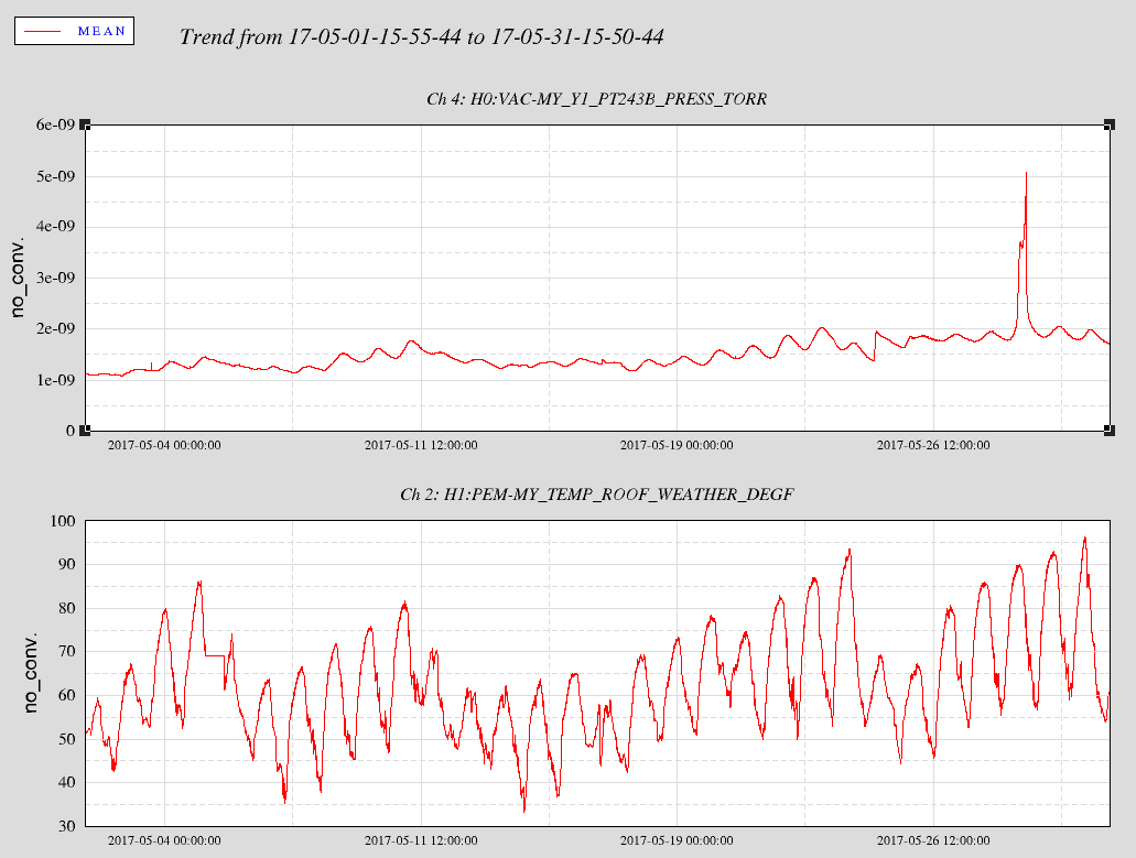
0900 hrs. local
8.9% full @ 0.8 psi exhaust.  PT243 1.8 x 10⁻⁹ torr

This is my last update for this aLOG entry - on my way to LHO
2302 hrs. local
CP3's level indication is 4.7% full with 0.5 psi exhaust and no change to PT243.
Midnight: 3.6% and 0.4 psi exhaust lressure. No change on PT-243 (2.0e-9 Torr). Exhaust temps are both 21C.
5/30/2017 0105 hrs. local
5.2% full, 0.5 psi exhaust pt243 @ 1.98 x 10⁻⁹ torr
2 am: 5.9% and 0.5 psi exhaust pressure. PT-243 = 1.94e-9 Torr.
0300 hrs. local
5.4% full @ 0.6 psi and 1.92 x 10⁻⁹ torr
4am
5.6% full @ 0.5 psi and 1.89 x 10⁻⁹ torr
0500 hrs. local
6.1% full @ 0.8 psi exhaust.  PT243 1.87 x 10⁻⁹ torr
6am
7.1% full @ 0.7 psi exhaust.  PT243 1.84 x 10⁻⁹ torr
0700 hrs. local
7.7% full @ 0.9 psi exhaust.  PT243 1.83 x 10⁻⁹ torr

We are using a T-size GN2 cylinder which is typically filled with 300cubic*ft of GN2.  So, (300cubic*ft)(28L/cubic*ft)(min/2L)(hour/60min)(day/24hour) = 2-3 days of flow
