Ops Shift Log: 05/15/2017, Day Shift 15:00 – 23:00 (08:00 - 16:00) Time - UTC (PT)
State of H1: Unlocked
Intent Bit: Engineering
Support: N/A
Incoming Operator: N/A
Shift Summary: Cheryl transition LVEA to laser safe for WP #6634. Pumping and what work closed gate valves will allow, continues.
Activity Log: Time - UTC (PT)
15:00 (08:00) Start of shift
15:10 (08:10) Chris – Taking the snorkel lift to End-X
15:23 (08:23) Aiden & TJ – In LVEA at the HAM4 HWS Table
15:55 (08:55) Karen – Cleaning in the LVEA
15:58 (08:58) Aiden & TJ – Out of the LVEA
16:20 (09:20) Cheryl – Transition LVEA to Laser Safe
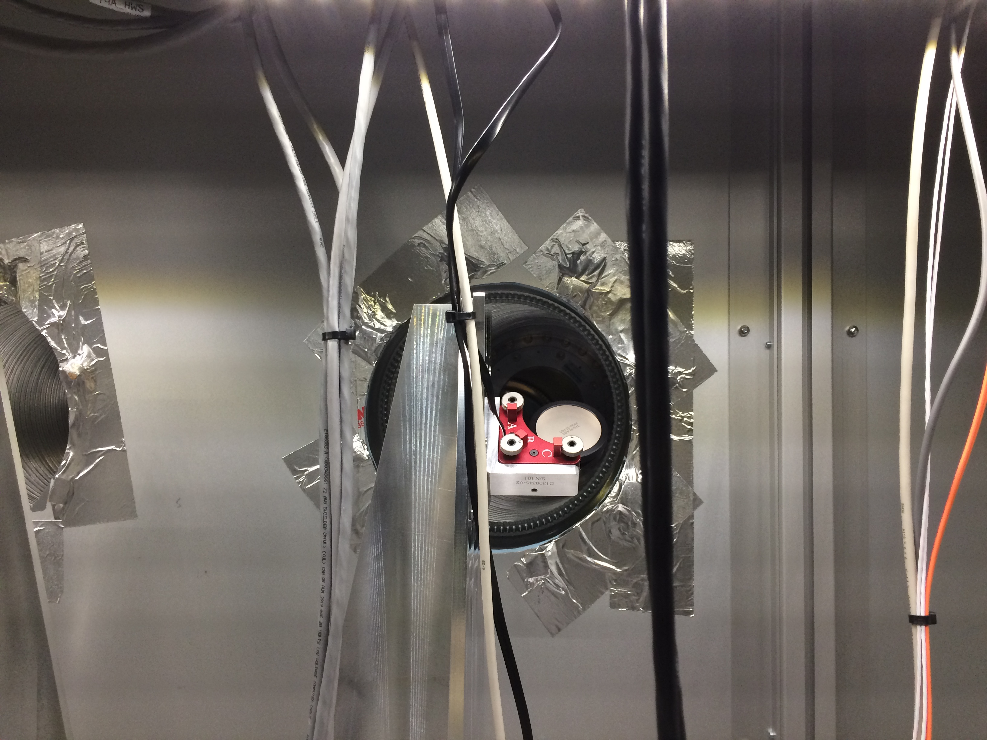
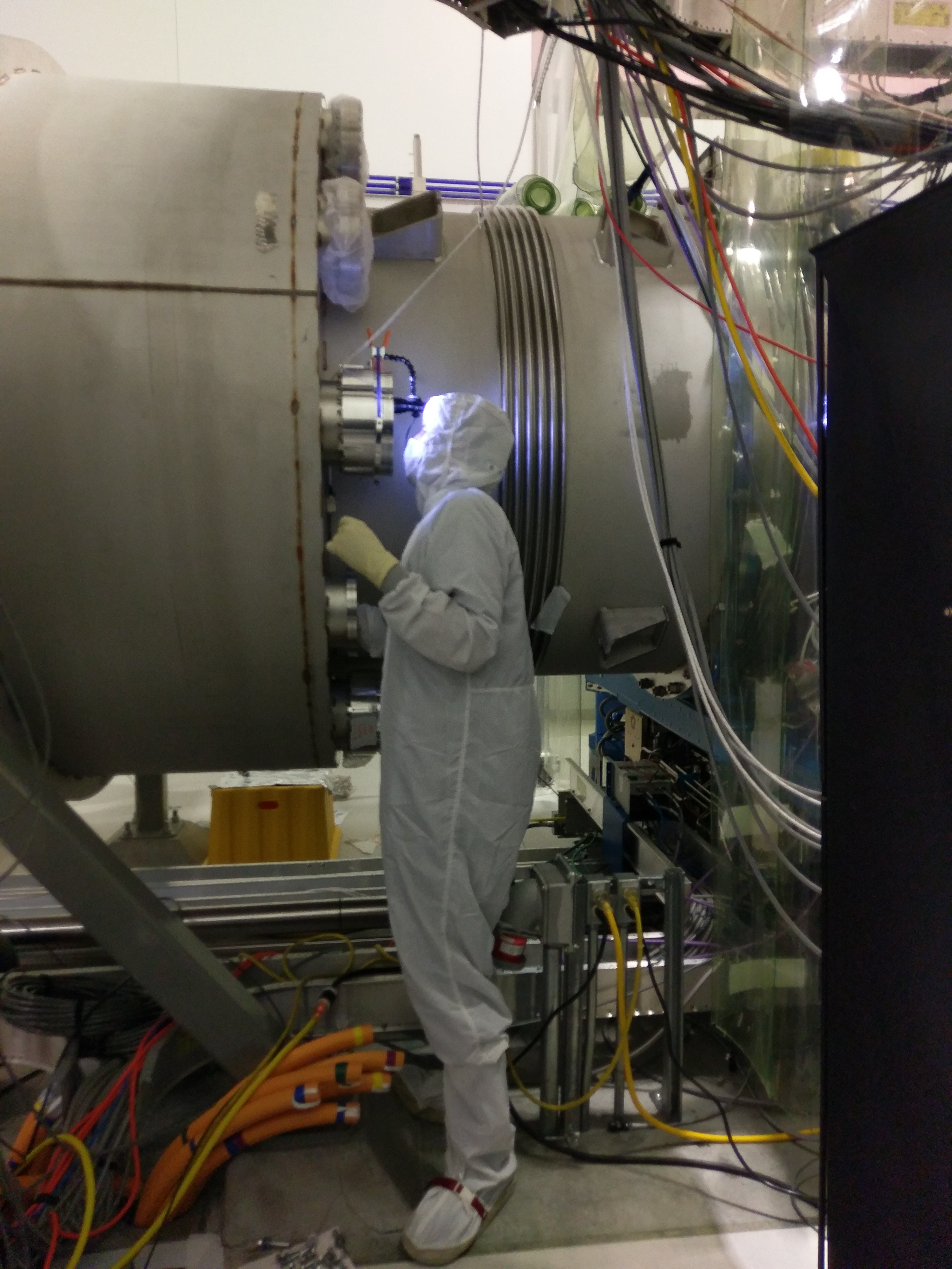
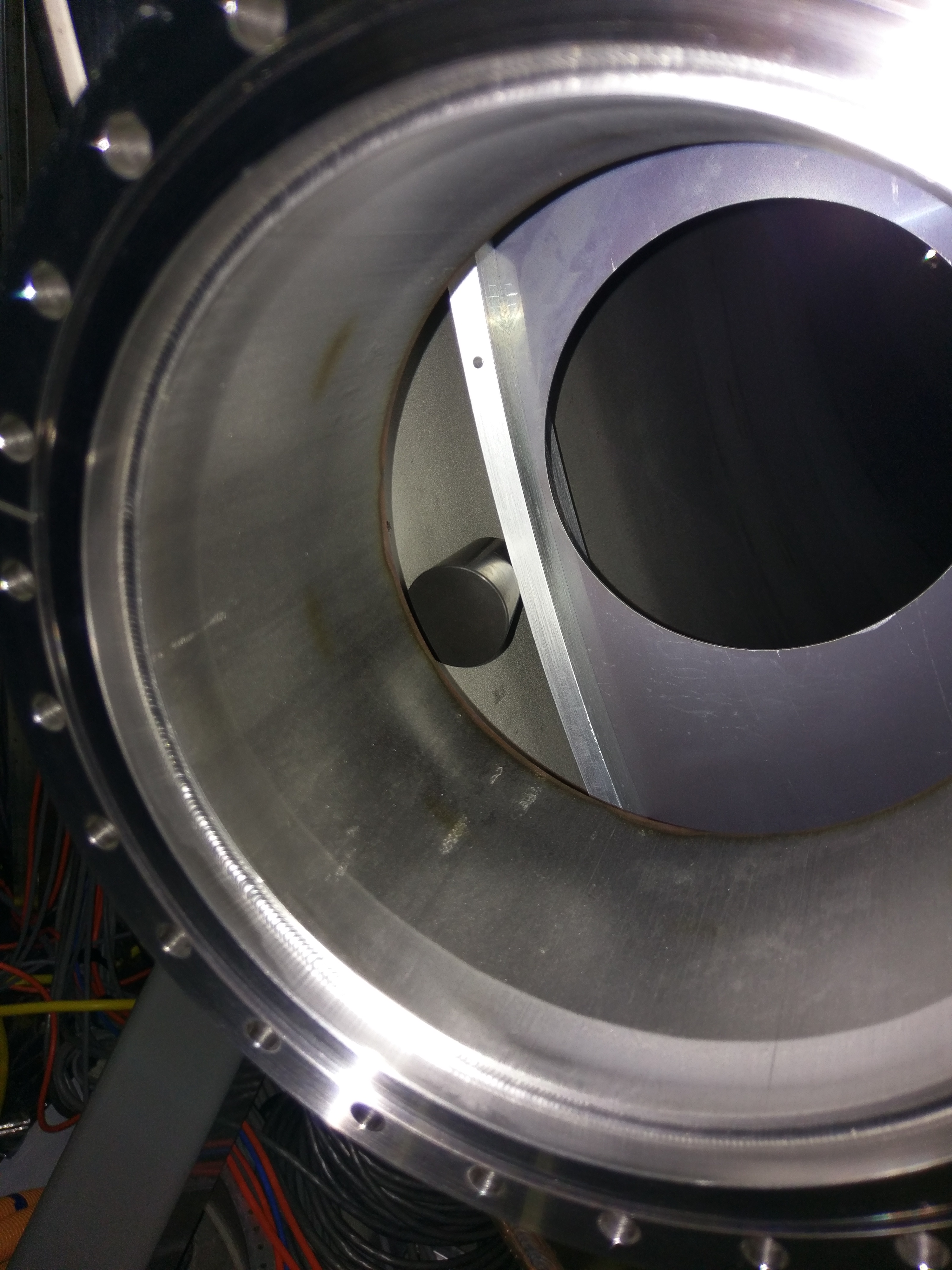
16:30 (09:30) Cheryl – Taking pictures from HAM2 view ports (WP #6634)
16:27 (09:27) Chris – Finished at End-X
16:27 (09:27) Chris – Going to Mid-X
16:35 (09:35) LVEA is laser safe
16:40 (09:40) Karen – Out of the LVEA
16:50 (09:50) Filiberto – Working with power supplies in Biergarten and CER
17:05 (10:05) Chandra – Leak checking at X-Beam manifold
17:05 (10:05) Jim – Going into LVEA to check on unlocking HEPI
17:25 (10:25) Jim – Out of the LVEA
17:50 (10:50) Corey – Inventory work in the Squeezer Bay
17:57 (10:57) Travis – Out of the LVEA
18:10 (11:10) HFD – On site to meet Bubba
18:15 (11:15) HFD – Driving Arms to check for fire hazards
18:25 (11:25) Aiden & TJ – Going to HAM4 HWS table
18:33 (11:33) Chris – Finished at Mid-X – coming back to CS
18:45 (11:45) Filiberto – Finished in the LVEA
18:50 (11:50) Cheryl – Out of the LVEA
19:04 (12:04) Peter & Jason – Going into the LVEA to look for equipment
19:10 (12:10) Peter & Jason – Out of the LVEA
19:11 (12:11) Corey – Out of the Squeezer Bay
19:20 (12:20) Aiden & TJ – Out of the LVEA
20:00 (13:00) Bubba & John – Craning cleanroom out of Biergarten
20:02 (13:02) Chris – Going into the LVEA
20:21 (13:21) Marc – Going to Mid-Y
20:38 (13:38) Restart Video4
20:50 (13:50) Travis – Going into the LVEA to recover parts
20:56 (13:56) TJ – Going into the LVEA
21:00 (14:00) Corey – Going into the Squeezer Bay for inventory work
21:06 (14:06) TJ – Out of the LVEA
21:17 (14:17) Cheryl – Going out to HAM2 IOT2R
21:23 (14:23) TJ – Going into the LVEA
21:25 (14:25) TJ – Out of LVEA
21:43 (14:43) Gerardo – Going to HAM2 IOT2R to attach light pipe
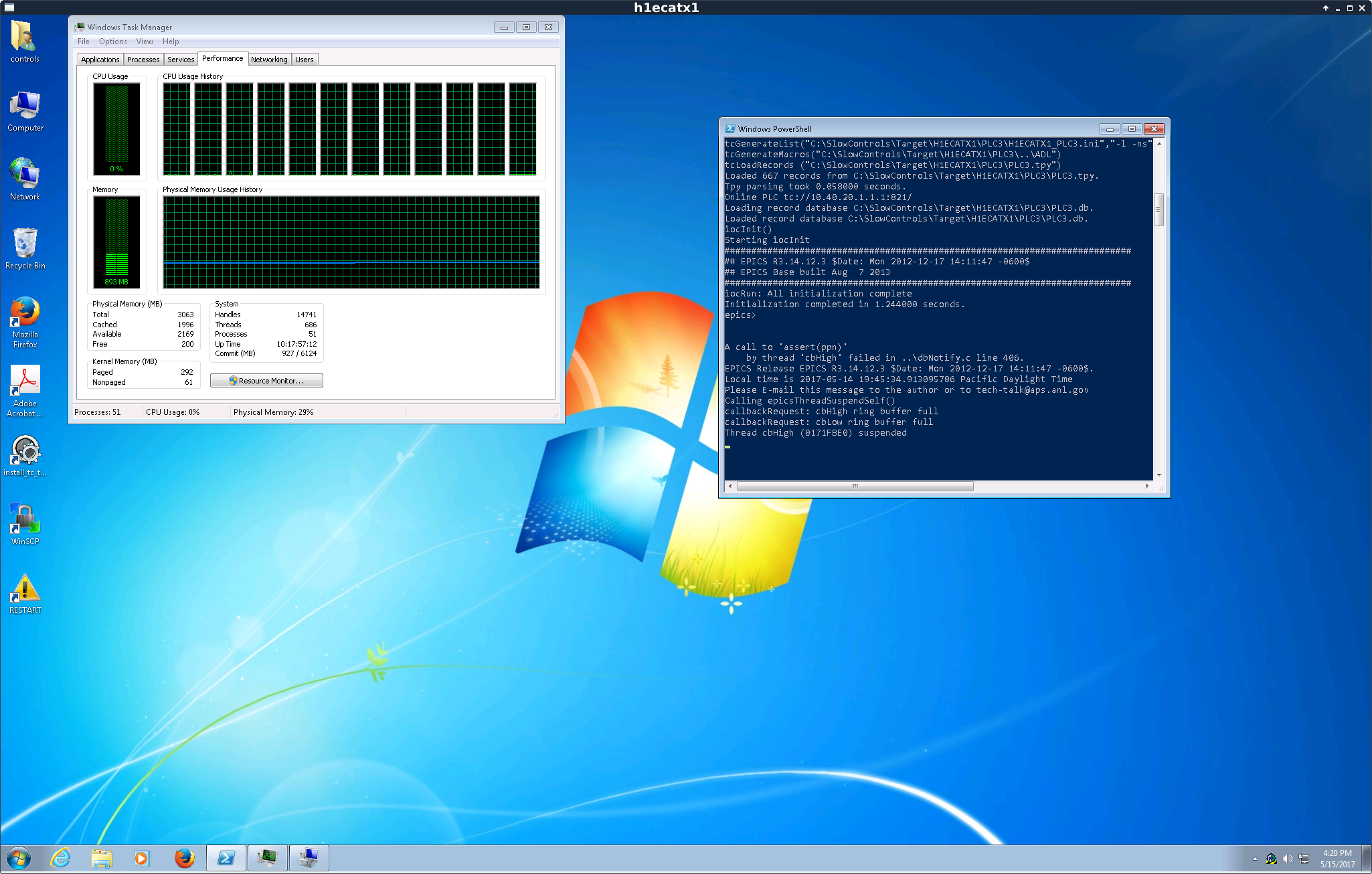
22:31 (15:31) Dave – Rebooting the Guardian machine to free up memory
22:46 (15:46) Robert & Pep – Going to End-Y
22:51 (15:51) Corey – Out of the LVEA
22:57 (15:57) Betsy & Travis – Going into the LVEA