I've used my IMC beam center measurements to calculate the change of the beam on IM1 in yaw, and propagated that change to the IO Faraday Isolator input, CalciteWedge1. The change on IM1 is calculated using an ideal IMC (centered beams) to recent beam spot measurements from March 2017. Nominal IM alignments are from the vent, July 2014, when the IMC REFL beam was routed through the IMs and the beam was well centered on the input and output of the IO Faraday.
My calculations show that the beam on CalciteWedge1 has moved +8.1mm, which is in the -X IFO direction, and the incident angle has changed by -1217urad, reducing the incident angle from 6.49deg to 6.42deg.
Beam Changes on IM1, IM2, and the IO Faraday input, CalciteWedge1:
| |
change |
units |
| im1 yaw, mm |
-6.8 |
mm |
| im1 yaw, urad |
253 |
urad |
| im2 yaw, mm |
-8.4 |
mm |
| im2 yaw, urad |
-1417 |
urad |
| cw1 yaw, mm |
8.1 |
mm |
| cw1 yaw, urad |
-1217 |
urad |
The beam change on IM1 is well understood, since it comes from the IMC beam spot changes. The IM positions can be assumed to have some error, however I've done the same calculations with IM positions from before and after the vent, and the change on CalciteWedge1 varies only by about 1mm.
A change of 8mm (+/-1mm) on the IO FI input is significant.
The optics inside the Faraday Rotator are only 20mm in diameter, and there is a small loss in aperture due to the optic mounts.

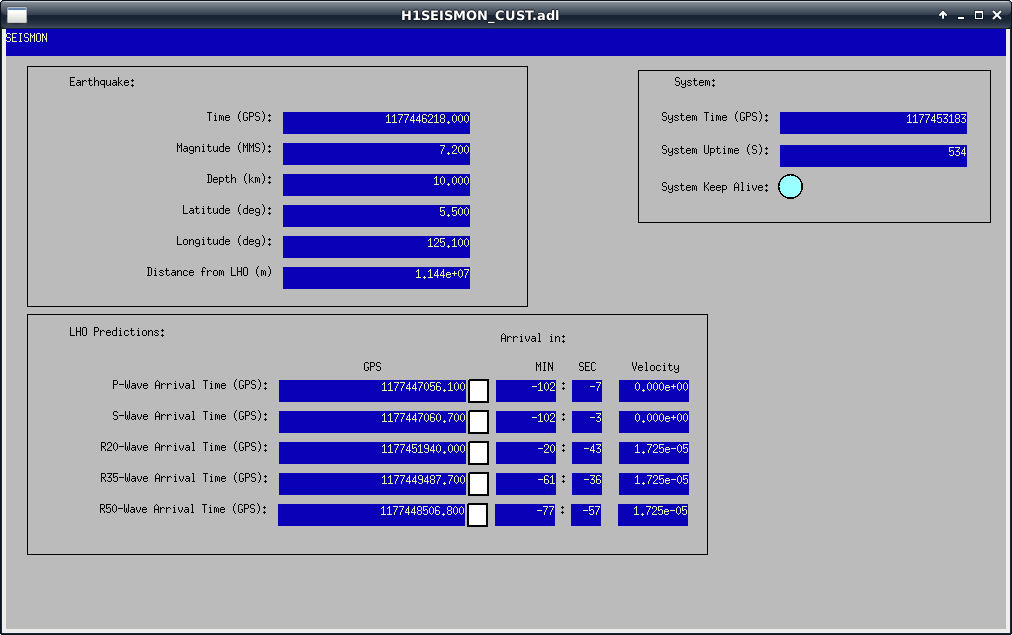

Whoa. Actually looks like we'll be shaken more by a quake from Alaska (5.4magnitude w/ 4.1um/s) which should be inbound soon.....watching & waiting.