Two maintenance items and one FAMIS task on the docket today: increase HPO pump diode currents and tweaking of the beam alignment into the PMC, and the weekly FAMIS PSL power watchdog reset. The following work was done with the ISS OFF.
HPO Pump Diode Currents
I increased the HPO pump diode currents and temperature tuned the diodes. A summary of the new and old pump diode currents is below in Table 1. Diode Box #1 continues to decay faster than the other 3 diode boxes. We want to replace an in-service diode box once its operating current exceeds 90% of its maximum. These DBs max out at 60A, so the target for replacement is 54A of operating current. Using this as a guideline, DB1 is beginning to get close to replacement.
Table 1: Summary of HPO Pump Diode Current Changes
| |
Operating Curent (A) |
| Old |
New |
| DB1 |
51.7 |
52.4 |
| DB2 |
51.5 |
51.9 |
| DB3 |
51.5 |
51.9 |
| DB4 |
51.5 |
51.9 |
Following this, I temperature tuned the diodes to maximize the output power of the HPO. A summary of the temperature changes is listed below in Table 2.
Table 2: Summary of Changes in HPO Pump Diode Temperatures
| |
Diode Box 1 (°C) |
Diode Box 2 (°C) |
Diode Box 3 (°C) |
Diode Box 4 (°C) |
| Old |
New |
Old |
New |
Old |
New |
Old |
New |
| D1 |
25.0 |
24.5 |
20.0 |
20.0 |
22.0 |
21.5 |
24.0 |
24.0 |
| D2 |
25.5 |
25.0 |
19.5 |
19.5 |
26.0 |
25.5 |
21.5 |
21.5 |
| D3 |
27.5 |
27.0 |
20.5 |
20.5 |
26.0 |
25.5 |
23.0 |
23.0 |
| D4 |
24.0 |
23.5 |
18.5 |
18.5 |
23.0 |
22.5 |
21.5 |
21.5 |
| D5 |
26.0 |
25.5 |
18.5 |
18.5 |
27.0 |
26.5 |
23.5 |
23.5 |
| D6 |
25.5 |
25.0 |
19.0 |
19.0 |
21.5 |
21.0 |
23.5 |
23.5 |
| D7 |
23.0 |
22.5 |
19.5 |
19.5 |
22.5 |
22.0 |
23.5 |
23.5 |
After this work, the HPO is now outputting 169.2 W.
PMC Beam Alignment Tweak
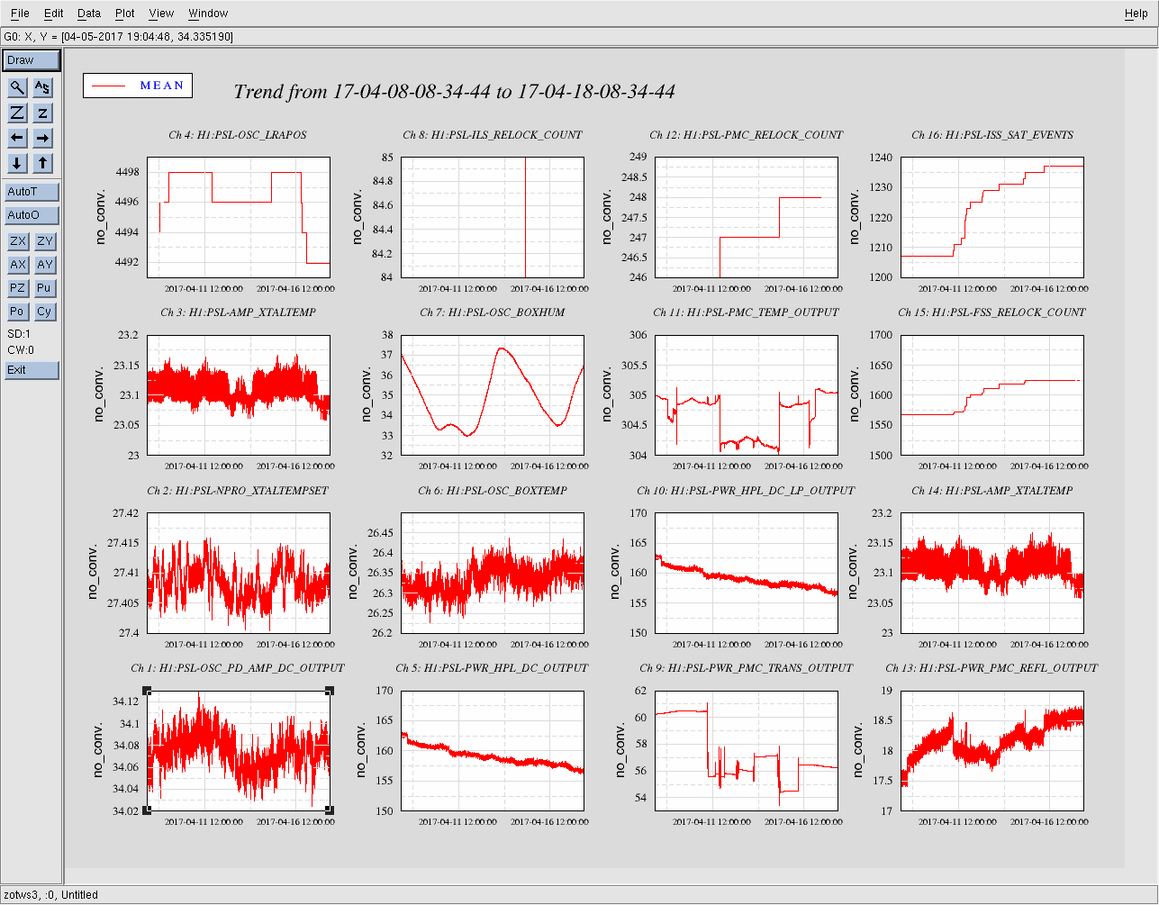
Next, with the ISS still off, I tweaked the beam alignment into the PMC. Only small tweaks were required to maximize the transmitted power. Unfortunately I was not able to recover as much transmitted power as usual; last time I tweaked this alignment, with the ISS turned back on the PMC reflected power was ~14W and the transmitted power was ~65 W. Now the best I could do, with the ISS turned back on, is 16.2W of reflected power and 63.9W of transmitted power. To me, this indicates a slight mode mismatch, which requires a PSL incursion to correct. For now, and for the scope of this work permit, the PMC transmitted power is >60W, which is our target for PMC transmission. This is sufficient for now, and we will plan a PSL incursion for the next maintenance window to investigate this possible mode matching issue.
This closes LHO WP 6578.
FAMIS 3646
During the course of the above work, I reset both PSL power watchdogs; this was at ~16:30 UTC (9:30 PDT). This completes FAMIS task 3646.


Unfortunately we could not get DMT hoft to send output downstream with this change. We are going back to calibration 1.1.5 for now.