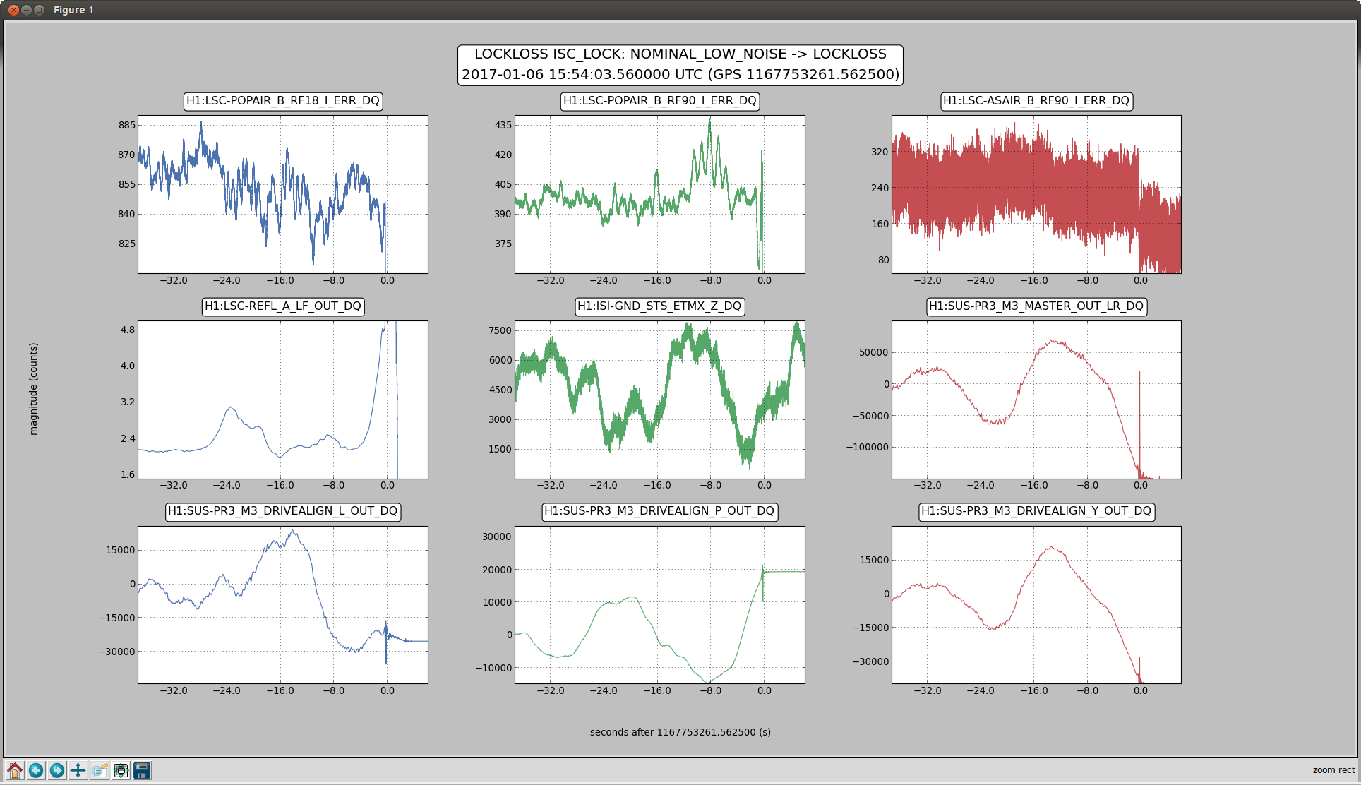
H1 has been getting more and more glitchy over the last 12 hours, and we're not sure why. Sheila, JeffK, Young-Min and I are trying to look into it, but we would very much appreciate Detchar help. If someone sees something that we should look into more closely, feel free to call the control room in addition to posting, so that we can get H1 back up and on its non-glitchy feet quickly.
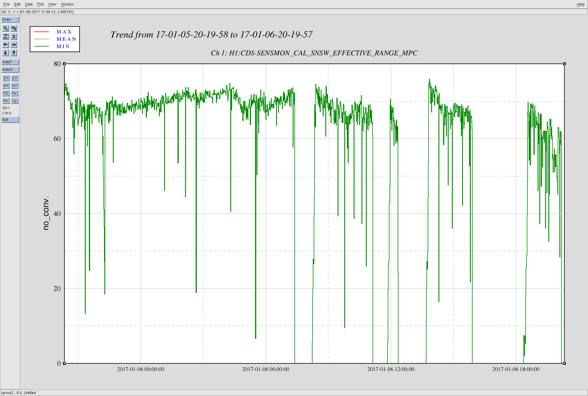
Attached is a screenshot of the range from the last day, but we're most concerned about the last 2 locks.
During the most recent lock, the constant low range toward the end (19:45 - 20:00 UTC 6Jan2017) appears to be from the sensor correction toggling of the Xend station ISI (see Jim's alog 33028 for details on why that was necessary), which was coincident with a broad band of extra glitchiness on the DMT Omega plot between 700Hz-1100Hz. We'd like to look into this separately, but we'll prioritize it below the major glitchiness at lower frequencies that we've had the last 2 locks.
Some things that could be helpful:
- Hveto - The analysis looks like it hasn't run yet for these 2 locks on the summary page, but we hope it'll point us in a useful direction.
- Scattering code - Can we tell where we're getting extra scattering, and if that's a big part of our problem?
Young-Min, Sheila Jeff Cheryl Jim Jenne
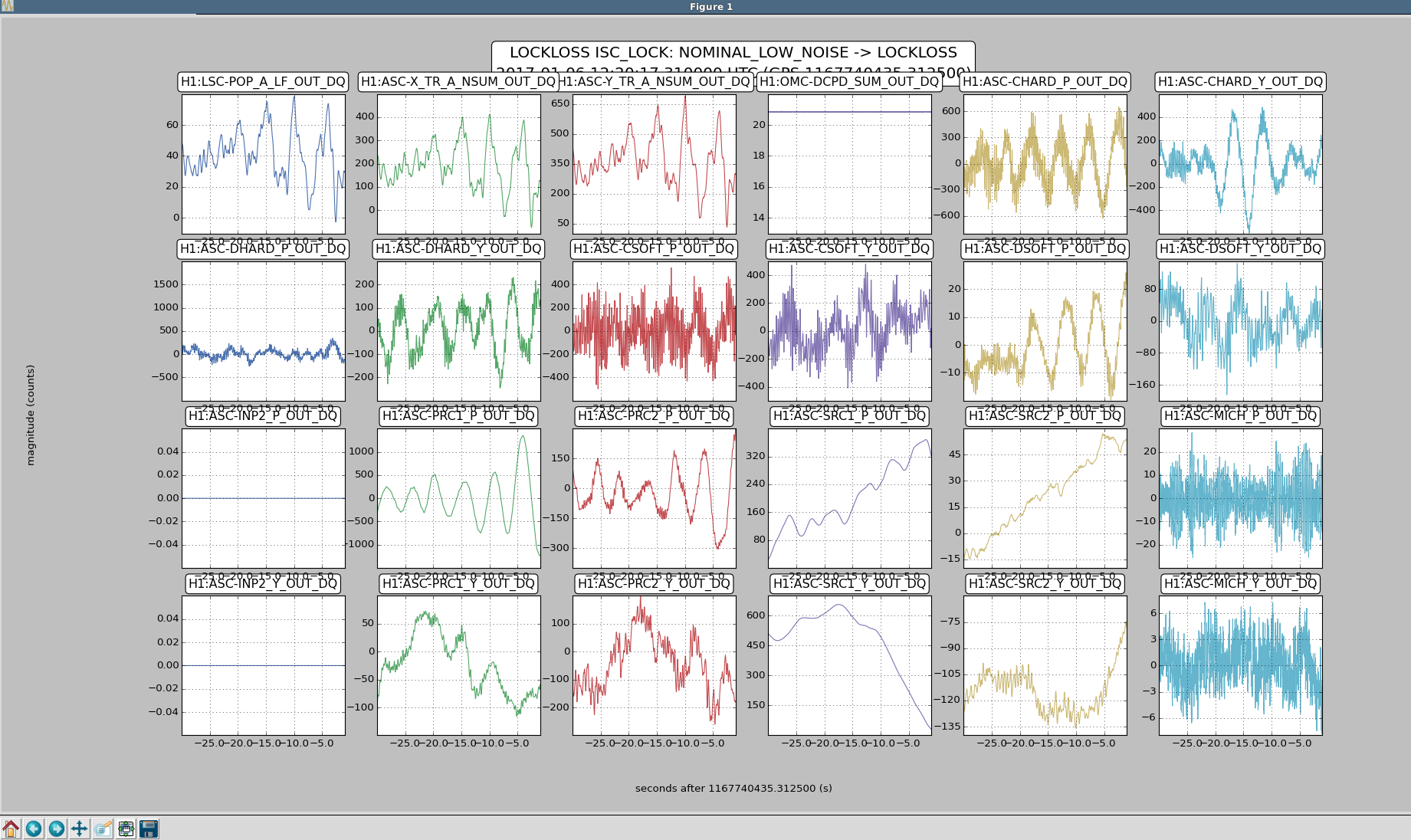
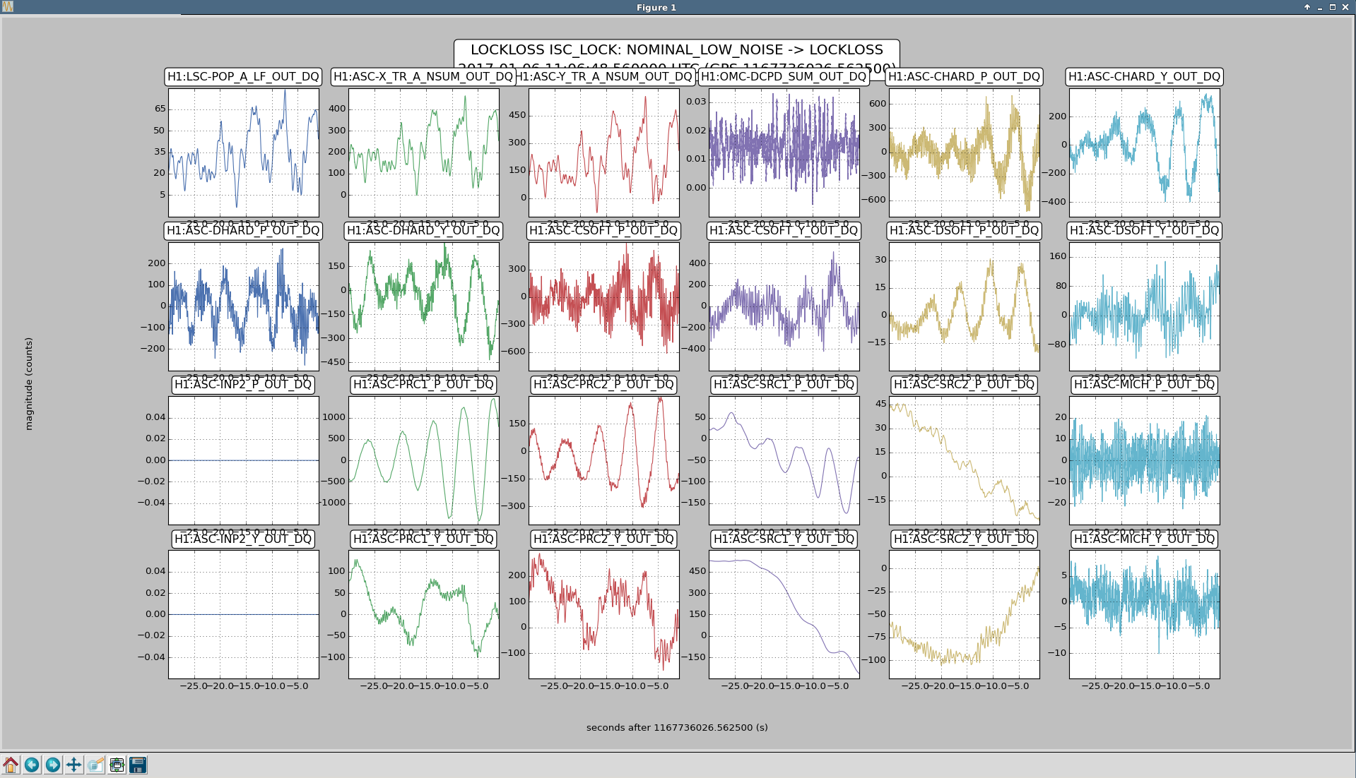
We had a lock stretch with large glitches and poor range starting at around 18:40 UTC to 20:09 UTC Jan 6th, Jenne is writing about some of the other issues with this lock stretch, but there might be a useful clue for investigating the 1084 Hz glitches in this data,
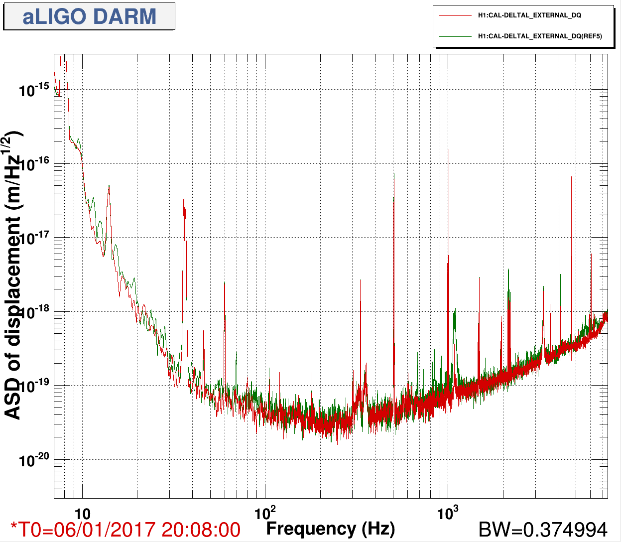
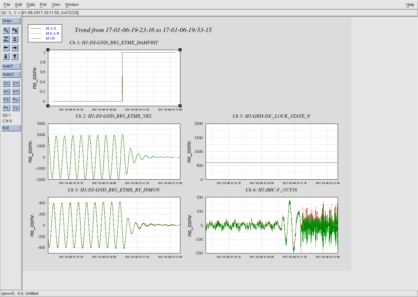
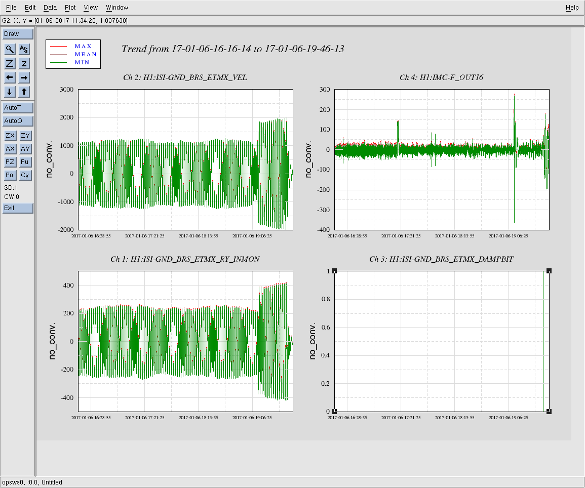
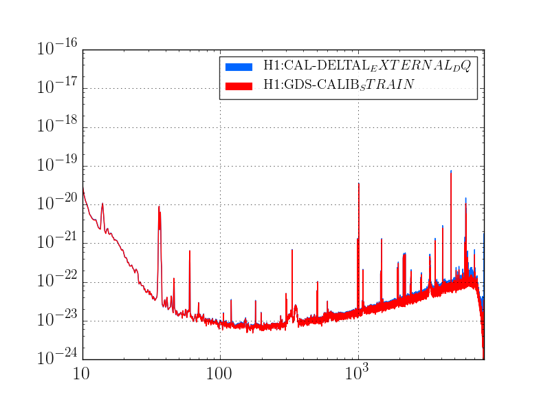
The behavoir of 1084Hz seemed normal until Jim Warner turned off the sensor correction at ETMX because of a problem with the BRS (alog 33028) at 19:44:49 UTC. The 1084Hz peak got much larger and became very non stationary, and other non stationary noise appeared at high frequencies (see comparison between red and green traces in the attached screenshot and spectrogram in summary page). This continued until 19:59:28 when Jim turned the sensor correction back on with the BRS damper on. We were planning to try an on off test, but lost lock at 20:09 UTC for unknown reasons.
To check the times when sensor correction is on, the channel to check is H1:ISI-ETMX_ST1_SENSCOR_GND_STS_X_FIR_GAIN which is 0 when sensor correction is off and 1 when it is on. To check on BRS damping the channel name H1:ISI-GND_BRS_ETMX_DAMPBIT, it was on from 19:40:12 UTC to 19:54:32 UTC
Because of the other problems with this lock stretch (which could be scattered light) Cheryl is now doing an initial alingment.
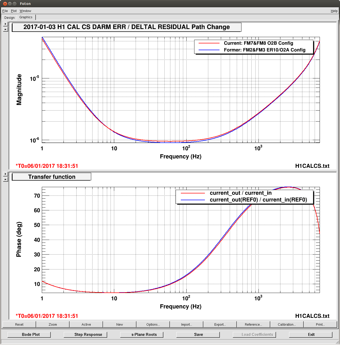
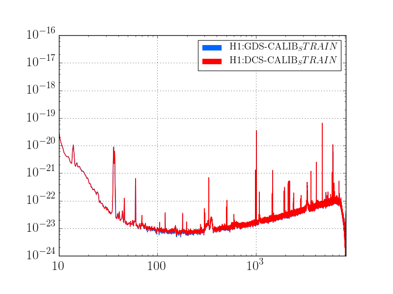
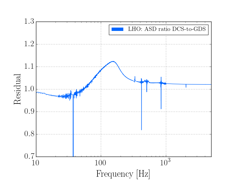
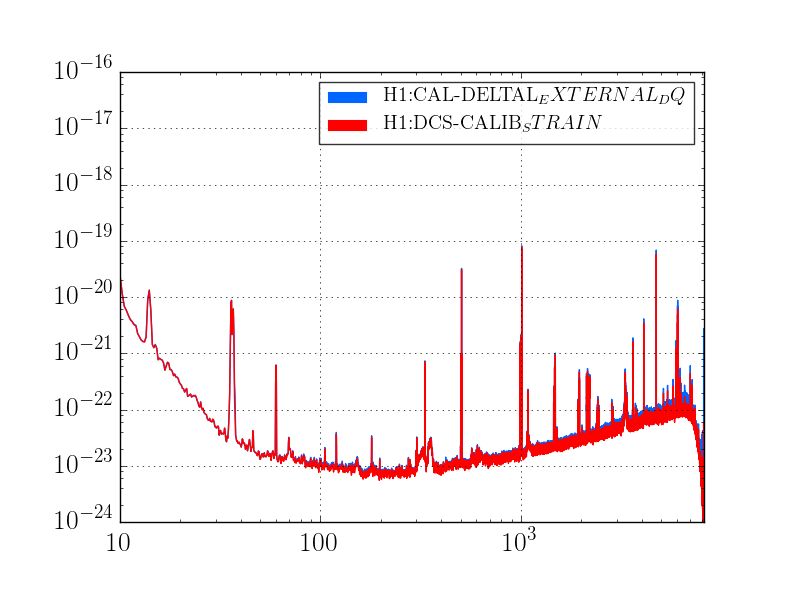
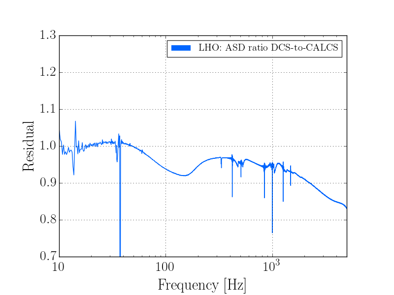
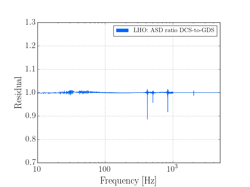
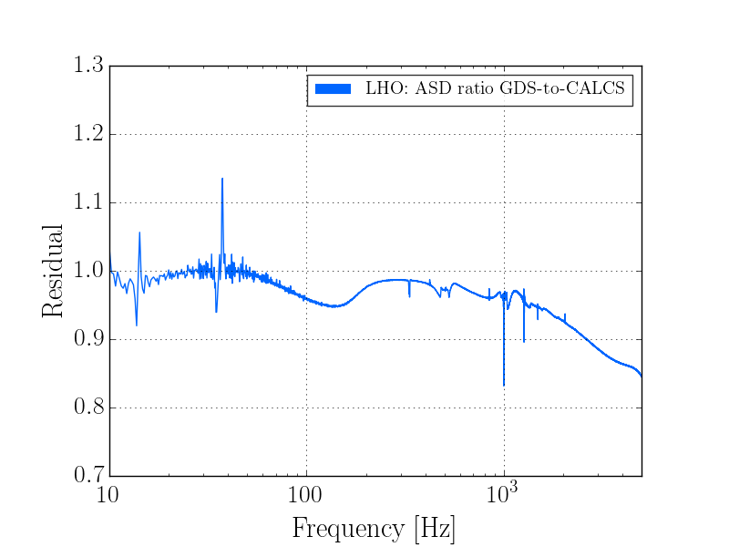
Ideas we've been spit balling around the room, which may help guide DetChar studies:

- We've been getting alarms that the Y END VEA temperature is swinging around. A theory: temperature causes ETMY and TMSY to drift -- perhaps differentially -- and the global ASC control system is forced to follow it. As it follows slowly, it begins to steer the IFO into places where scattered light causes more problems, and hence glitchiness. A correlation study of temperature in the Y VEA with alignment and glitch rate would be sweet. (Note Cheryl has already trended the position of the ETMs, and found that ETMY is moving around much more than ETMX.)

- Cheryl has also been moving around the IMs and has found that the IMC has moved substantially over the course of a few days. Other angle to attack would be alignment of the input optics vs. glitch rate, where again, the idea is that if the input pointing to the IFO is moving around, then the global ASC system is forced to follow it, and perhaps there are bad corners of alignment space that are more susceptible to scattered light and/or non-stationary.

- I'll state for the record, that this has NOTHING to do with the calibration change (LHO aLOGs 33025 and 33026), which change the response in a very stationary way.

- Jim's sensor correction ON/OFF (LHO aLOG 33031) and/or BRS damping ON/OFF study (LHO aLOG 33028) is another interesting avenue to explore.

Because of all of the above speculation, we're
- Restoring the IM alignment to it's "nominal" location from a Dec 8 2016 lock stretch early in O1.
- Running initial alignment
- We'll do more sensor correction ON/OFF studies when we get back up if LLO is still not observing.

But yeah -- we'll take any and all help we can get. Feel free to hop on the LIGO Control Rooms TeamSpeak channel.
Here are some hveto results for today:
Between 1-2048Hz - https://ldas-jobs.ligo-wa.caltech.edu/~laura.nuttall/detchar/hveto/20170106/
Between 10-1000Hz - https://ldas-jobs.ligo-wa.caltech.edu/~laura.nuttall/detchar/hveto/20170106_10_1000kHz/


