6:09 Bubba on his way to the site to investigate instrument air.
16:25 Initial alignment: Input align not showing any IR. Trended IM4 and PR2 after successfull ALS alignment. Still no luck. Going to full lock to further assess the need(s) for continuing IA.
16:35 Bubba on site
16:40 Johnathan called to inform me of a tour that he's meeting on site at 10:00PST
16:45 Both TCS Lasers tripped off.
16:49 Set H1 Observatory Mode to Unknown due to investigation of TCS issue.
16:57 John W on site going to assist Bubba
18:30 Checked on and cycled the TCS lasers
18:38 contacted Aiden and then Alistair
19:00 Granted remote access to Alastair
19:26 Carlos granted remote access
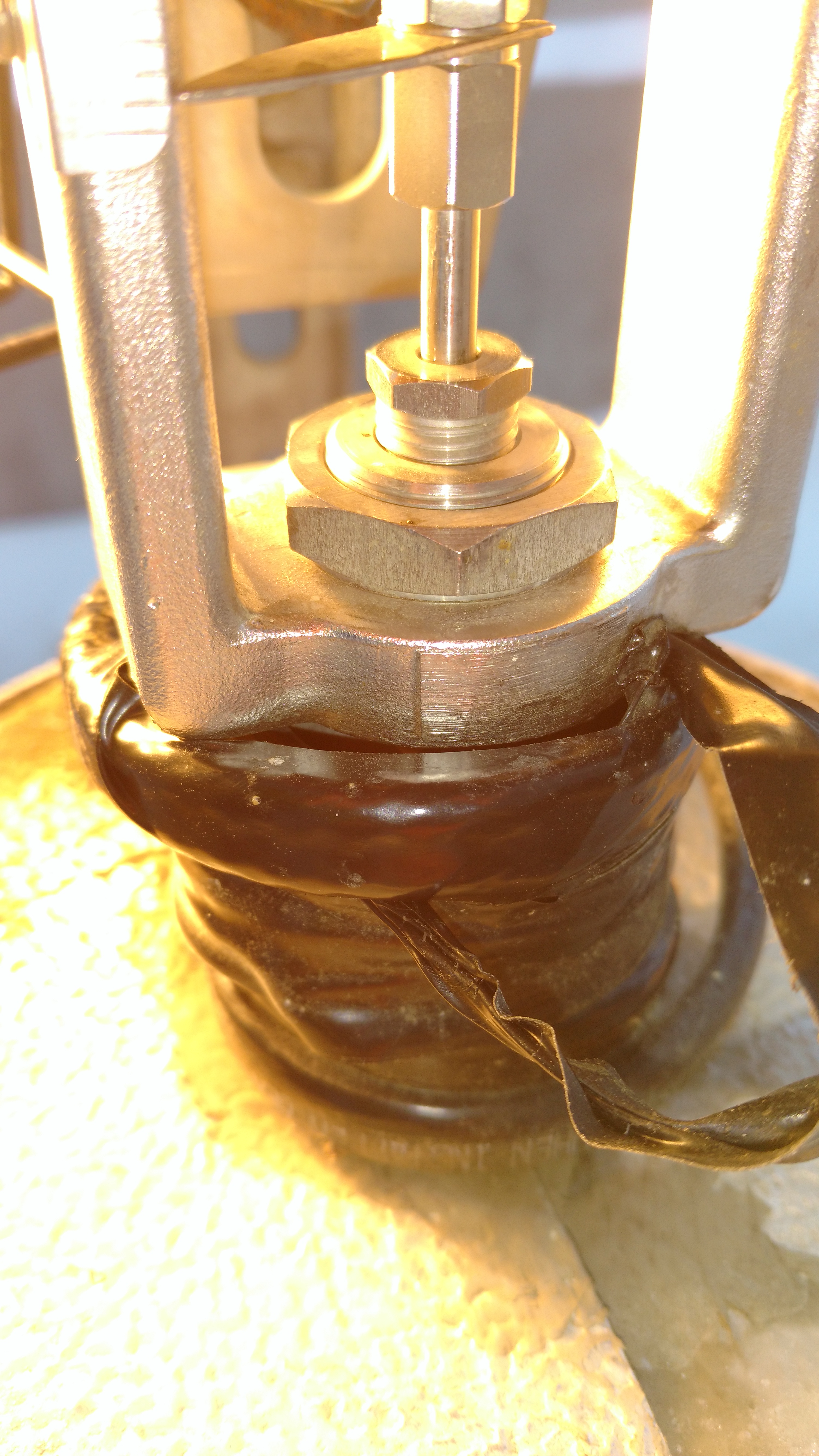
19:45 I spoke to Fil on the phone. It has been determined that there's a hardware error. He's heading to the site to troubleshoot.
23:43 Having an unusually hard time re-aligning arms
16:25 Handing off to Cheryl

Also, since we were already out of Observing and LLO is down, I took the opportunity to run A2L.