sheila.dwyer@LIGO.ORG - posted 21:04, Friday 02 September 2016 (29477)
reshaping CSOFT pitch, other locking today
Overall message:
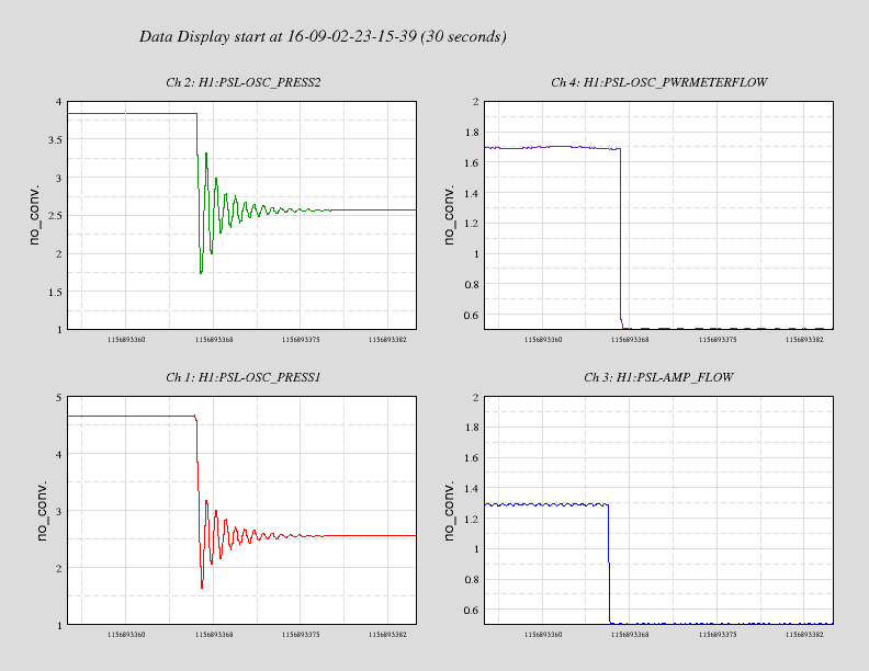
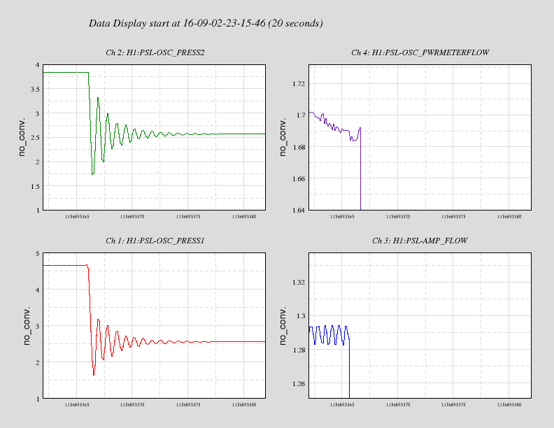
- We had trouble powering up today because of the CSOFT radiation pressure instabilty (dPdtheta). I reshaped the ASC control filter so we should have 20dB of supression, and this seems to have taken care of the problem.
- We have tried to do the coil driver switching twice today, and broken lock both times, seemingly because of a 2 Hz instability that only rings up durring the coild driver switching. We might want to separate the test mass coil drivers from the triples, so we can narrow down what the problem is.
- We decreased the gain of PRC2Y from -2000 to -14000 to avoid a not very stable ugf at 2 Hz.
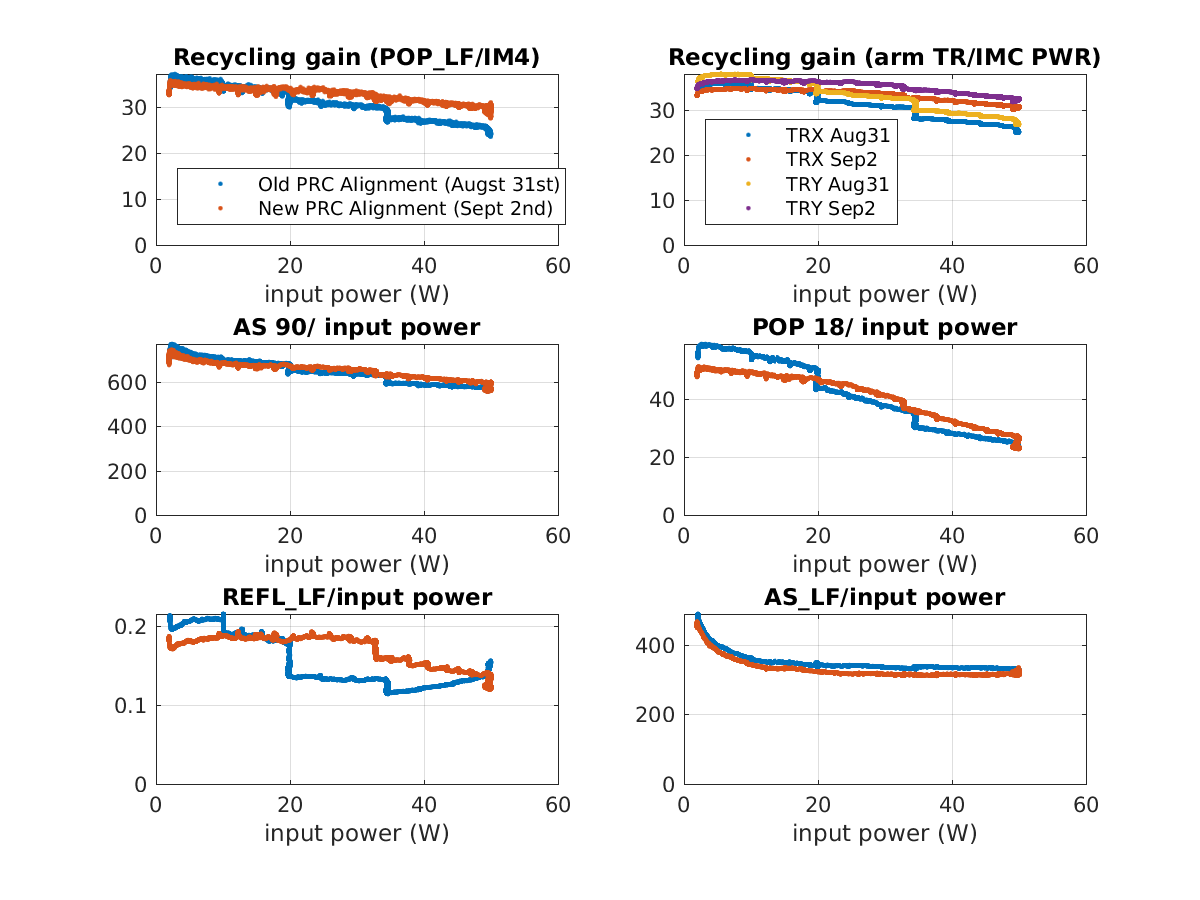
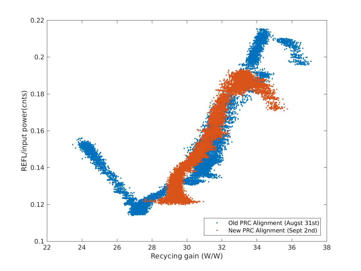
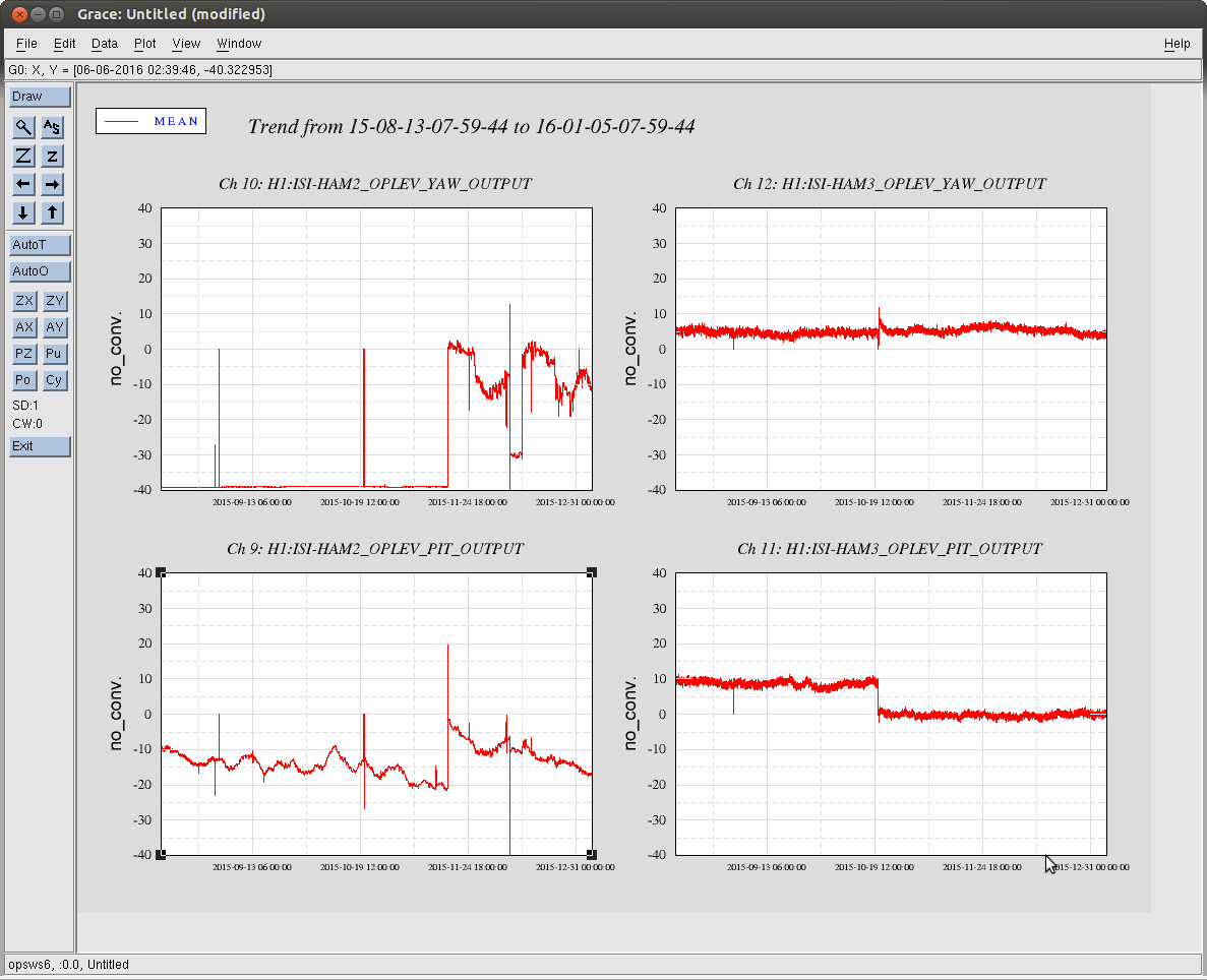
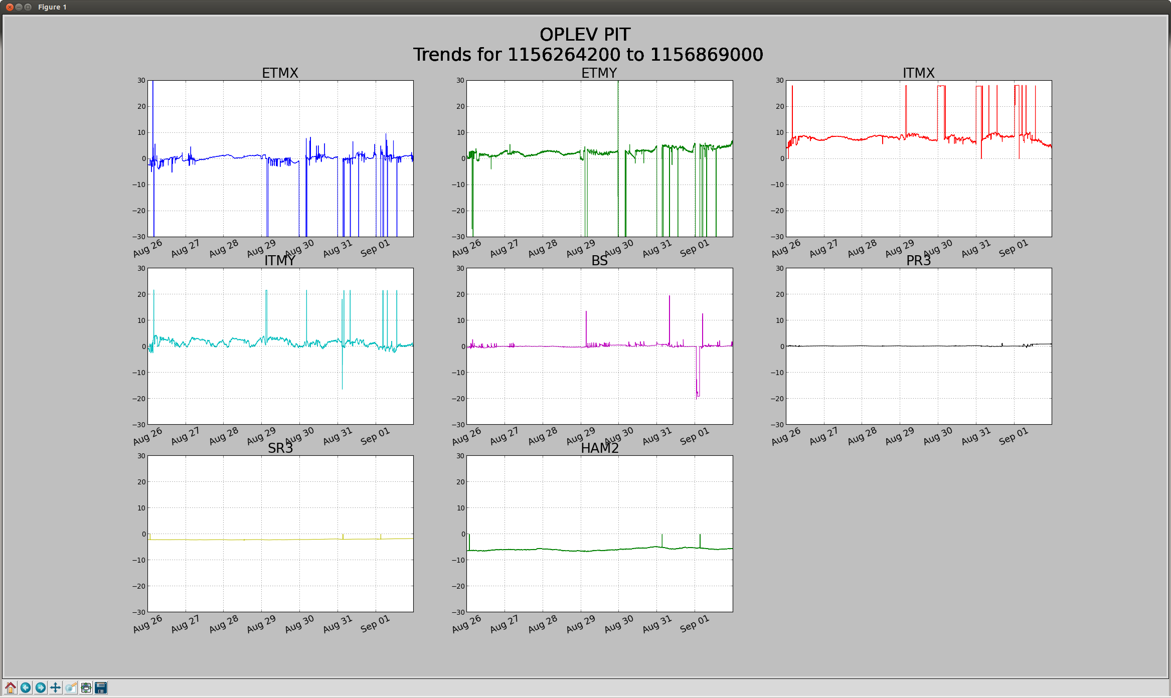
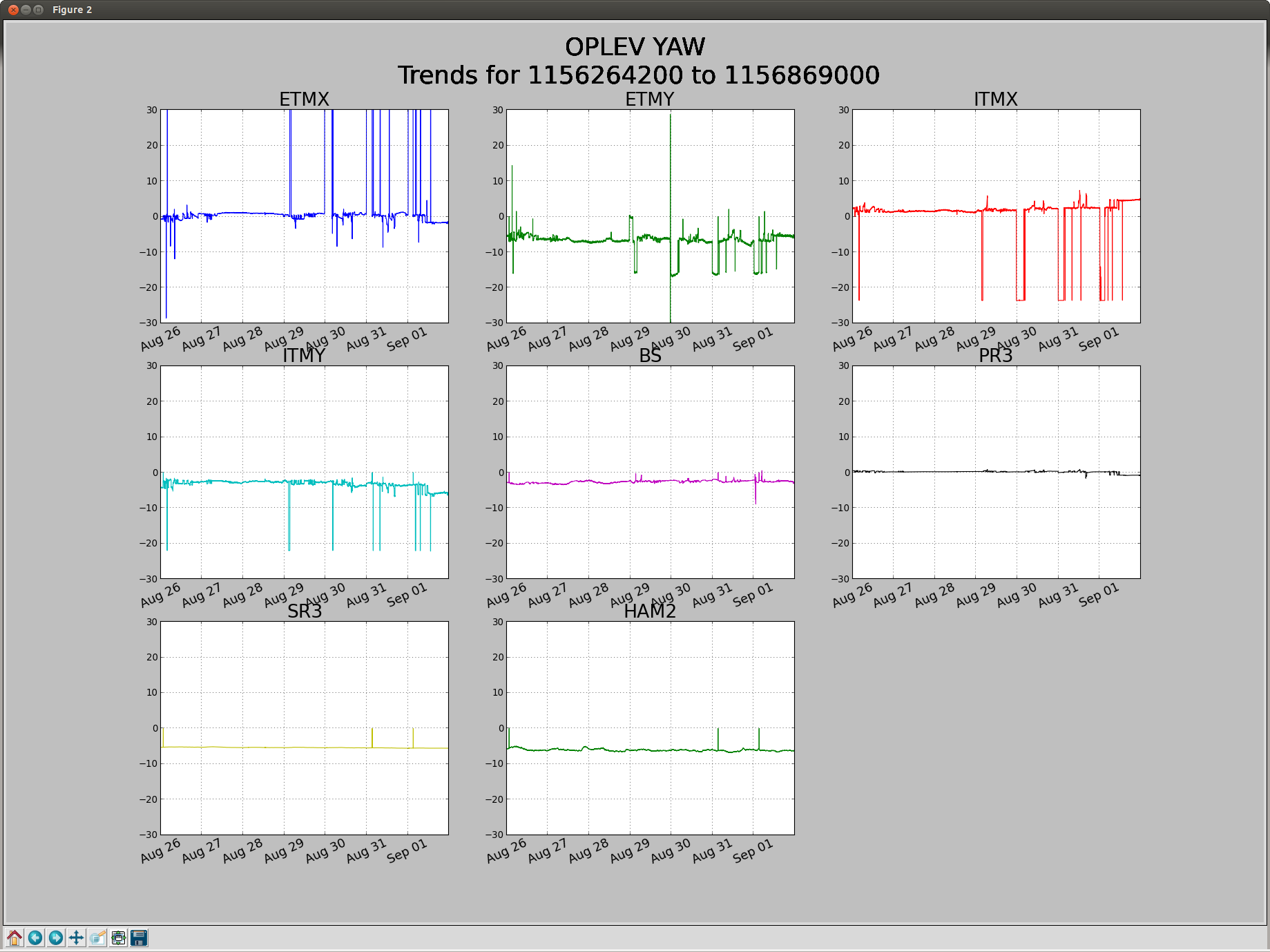
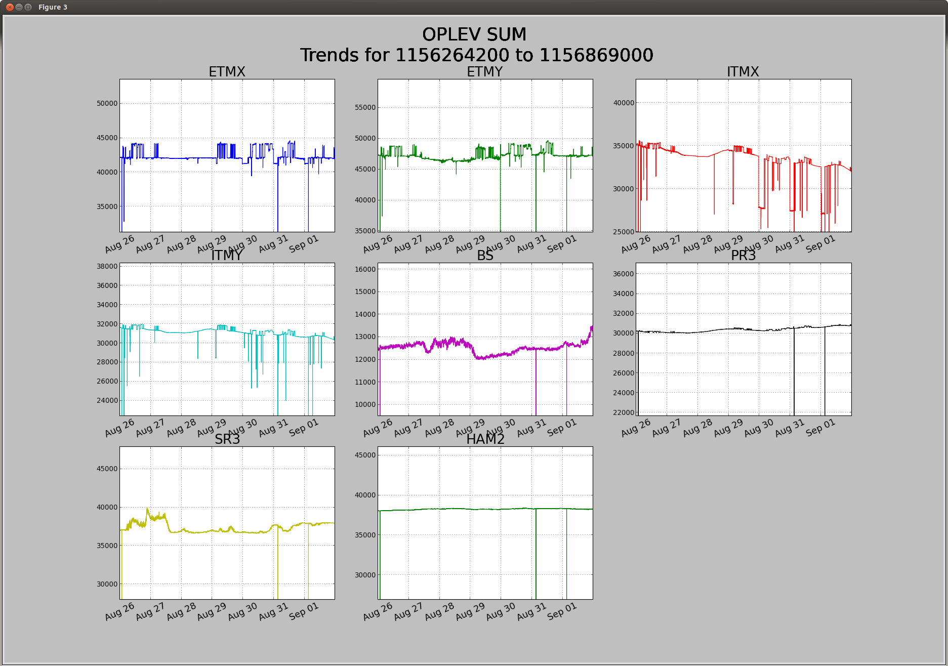
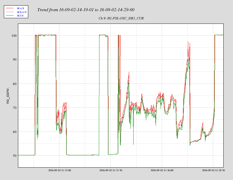
- When we power up to 50 Watts with a recycling gain of around 31, the lock only lasts about 20-30 minutes. There is a slow drift of sideband powers that cannot be fixed by moving PR2 yaw or BS pit or yaw. It could be a X arm soft yaw drift based on oplevs, we can try using a dither line to monitor the spot position on ETMX and try adjusting the soft offsets this way.
More about CSOFT PIT:
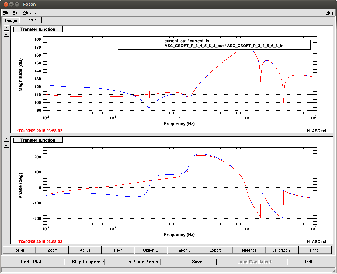
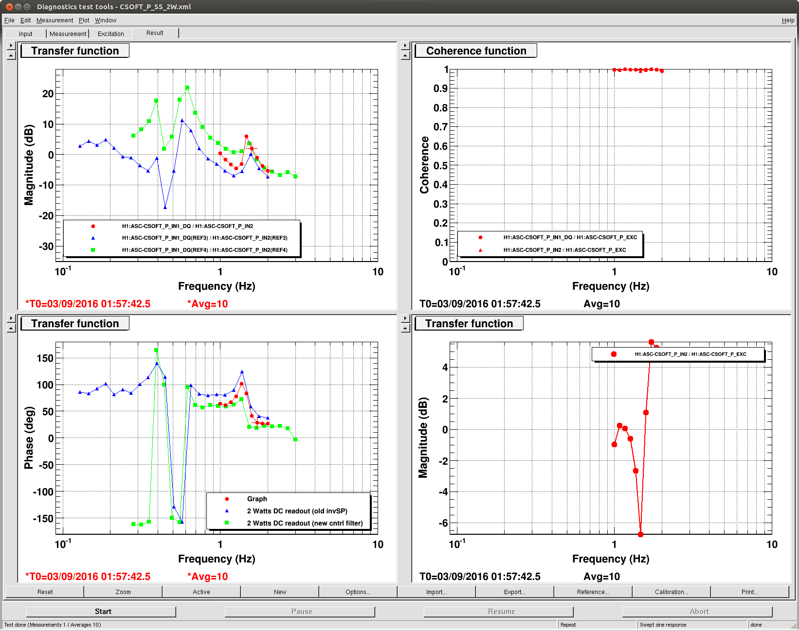
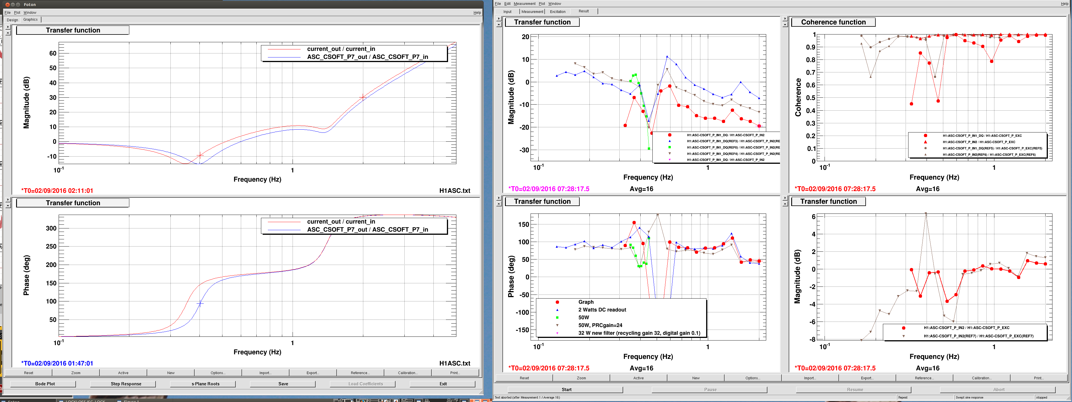
We were using a control filter that had a pair of complex zero compensating the 0.4 Hz resonance, which meant we had very little gain to supress the instability using ASC. I changed this to a single real zero, which gives us 20 dB gain at the instability frequency. The filter comparison is attached, and a measurement taken at 2 Watts. In the green measurement I had made a msitake in the filter at 1.5 Hz, the red measurement is with this fixed and the phase should be unchanged from the old design at these frequencies.
Images attached to this report