Tonight we again weren't able to engage the soft loops without pulling the sideband powers down and dropping lock, so I spent a little time on ASC.
For one thing I looked at the phasing of AS36 A to see if we can reduce the SRM signal in the Q phase. The reasoning for this is that the SRC loops are sensitive to the soft arms through AS_C, and if the BS is also sensitive to SRM this could be one way that moving SOFT misalings the beamsplitter. However, it looks like we are already kind of using a phase that minimizes the SRM signal in Q, (-140), so I left this as is.
I also had a look at the best combination of TMS QPDs to use, since we retuned this on saturday I was curious to see if the combination had changed today with a different alignment. I checked only TMSX pit, but it had only changed by 1%, even with the soft loops off.
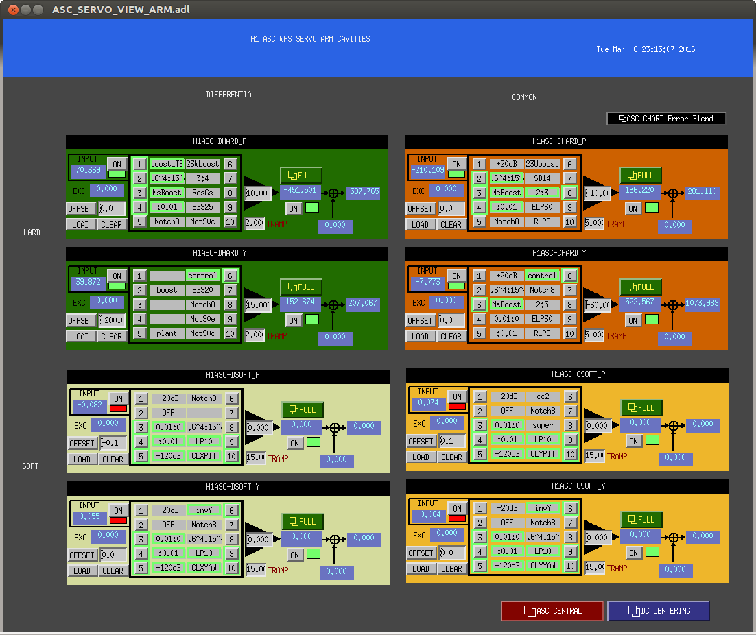
Lastly, I tried to increase the bandwidth of the CHARD loops, in part because we know we need to do this, and in part because CHARD is cross coupled with the yaw loops and there is a long slow osciallation in all 3 loops due to this. A screenshot is attached with settings that result in CHARD BWs similar to the DHARD ones, this initially does seem to reduce the long slow oscillation of the soft loops, but we still have the problem that the slow loops misalign the vertex. I've added these settings, which are engaged with a lower gain and not the boosts on, to the guardian, but they will probably add noise, so we can reduce their gains when we want to go to low noise.