corey.gray@LIGO.ORG - posted 15:28, Tuesday 16 February 2016 (25572)
PSL Watchdog Reset Performed
At 23:03UTC (3:03pmPST) I reset the PSL Watchdog this afternoon & CLOSED FAMIS Request #3585.
At 23:03UTC (3:03pmPST) I reset the PSL Watchdog this afternoon & CLOSED FAMIS Request #3585.
13:55 PST h1tcscs restarted
14:28 PST h1isietmy restarted
14:28 PST DAQ restarted
DAQ restart captures above model changes plus addition of all vacuum controls channels.
The h1boot-backup computer crashed with a kernel panic sometime Friday afternoon (Feb. 12), rebooted using the reset button.
This was moved last week.
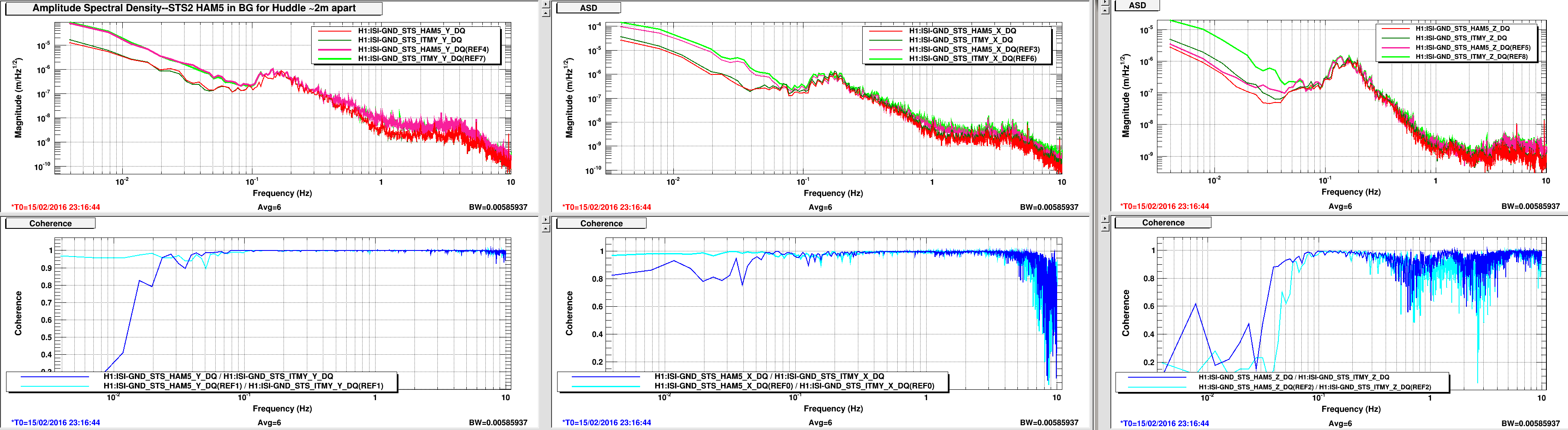
Attached are some ASDs and coherence plots. The reference traces are from a time of 20 to 30 miles winds this morning and the current traces are from an early time in the weekend when things were much quieter.
The Y axis looks good with strong coherence and similar spectra responding to the wind-tilt as expected. The X axis similarities are okay but not as strong as Y's. We don't understand the Z axis as the HAM5 unit does not respond to the wind like the ITMY seismometer and the coherence is bad compared to the X and especially the Y.
Aidan is making changes to h1tcscs which requires reading EPICS channels from the Beckhoff system. Here is the current number of H1 models which use CA to read/write data to external systems.
| model with ez_ca_read parts | number of channels read |
| h1ioppemmx* | 1 |
| h1ioppemmy* | 1 |
| h1odcmaster | 5 |
| h1pslpmc | 1 |
| h1sushtts | 1 |
| h1tcscs | 14 |
| model with ez_ca_write parts | number of channels written |
| h1psliss | 16 |
| h1pslpmc | 1 |
* The mid station IOP models lack a full timing system (no IRIGB signal) and instead get their GPS time from the DAQ via Channel Access.
The list of EZ_CA_[READ/WRITE] channels was obtained by:
cd /opt/rtcds/lho/h1/release/src/epics/fmseq
ls|grep -v "_daq"|xargs grep "EZ_CA_READ"
ls|grep -v "_daq"|xargs grep "EZ_CA_WRITE"
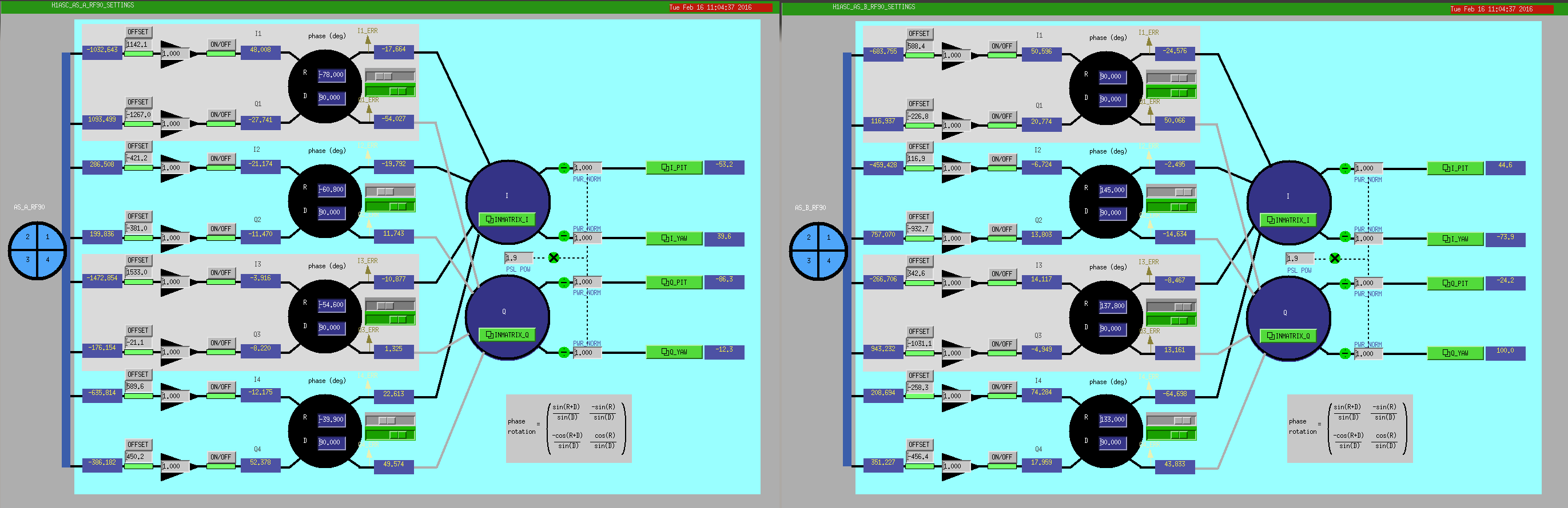
Set the phase using the in-lock stretch from some days ago. We can in principle just change the DC3 and DC4 input matrix and start RF-centering.
I have turned off two heaters in the LVEA. HC4 and HC5 were both set to 4ma control at 18:50 utc.
Bubba and I were able to crane the Genie manlift over the Y beam manifold this morning in order to continue the crane rail work.
GV5 and GV7 were soft closed for the duration from UTC 16:15 to 16:53.
The crane behaved normally.
Average LVEA temperature quickly came back but there are jumps in indivisual sensors, some show large change (0.5 to 0.8 C).
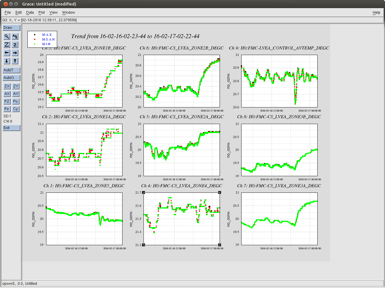
Are complete. I will post plots when I get a chance.
Here are the plots.
Laser Status:
SysStat is good
Front End power is 32.63W (should be around 30 W)
Frontend Watch is GREEN
HPO Watch is RED
PMC:
It has been locked 11.0 days, 23.0 hr 23.0 minutes (should be days/weeks)
Reflected power is 3.203Watts and PowerSum = 25.7Watts.
FSS:
It has been locked for 0.0 days 12.0 h and 23.0 min (should be days/weeks)
TPD[V] = 1.415V (min 0.9V)
ISS:
The diffracted power is around 8.004% (should be 5-9%)
Last saturation event was 0.0 days 12.0 hours and 23.0 minutes ago (should be days/weeks)
12 Counts on HAM5
Den made some modifications to our DRMI that he thinks might help us lock faster.
We had all of our integrators zero history immediately, Den added 1 second ramps to the 4:0 in MICH and the 10:0.1 in PRCL with the idea that this can reduce transients when they turn on.
He also changed our triggering so that SRCL and MICH are triggered together at 20 counts off at 10 coutns (this is about 1/3 of the power build up of POP18). Before SRCL was triggered at 2 counts.
Den also increased the PRCL gain from 11 to 15, removed the triggering of PRCL FM3 (10:0.1) and engaged it by hand after it locked. (the idea for higher gain being that it is better to supress PRCL well in the SRCL error signal).
He set the SRCL gain to -20 from -45.
DRMI locked in about two minutes. Its probably worth testing these settings out more and maybe making an alternate DRMI locking guardian state for testin new settings to see if we can reliably get a faster DRMI time.
We had an unusual HEPI trip (ETMX) just now. There doesn't seem to be much happening seismically except for some small wind gusts (not reaching 20mph). HEPI tripped as well as stage 1 of the ISI, but we are re isolated now and don't seem to have any problems.

We've just had another similar trip of ETMX HEPI, this time at the same time as a 40 moh gust of wind. The plotting tool didn't work.
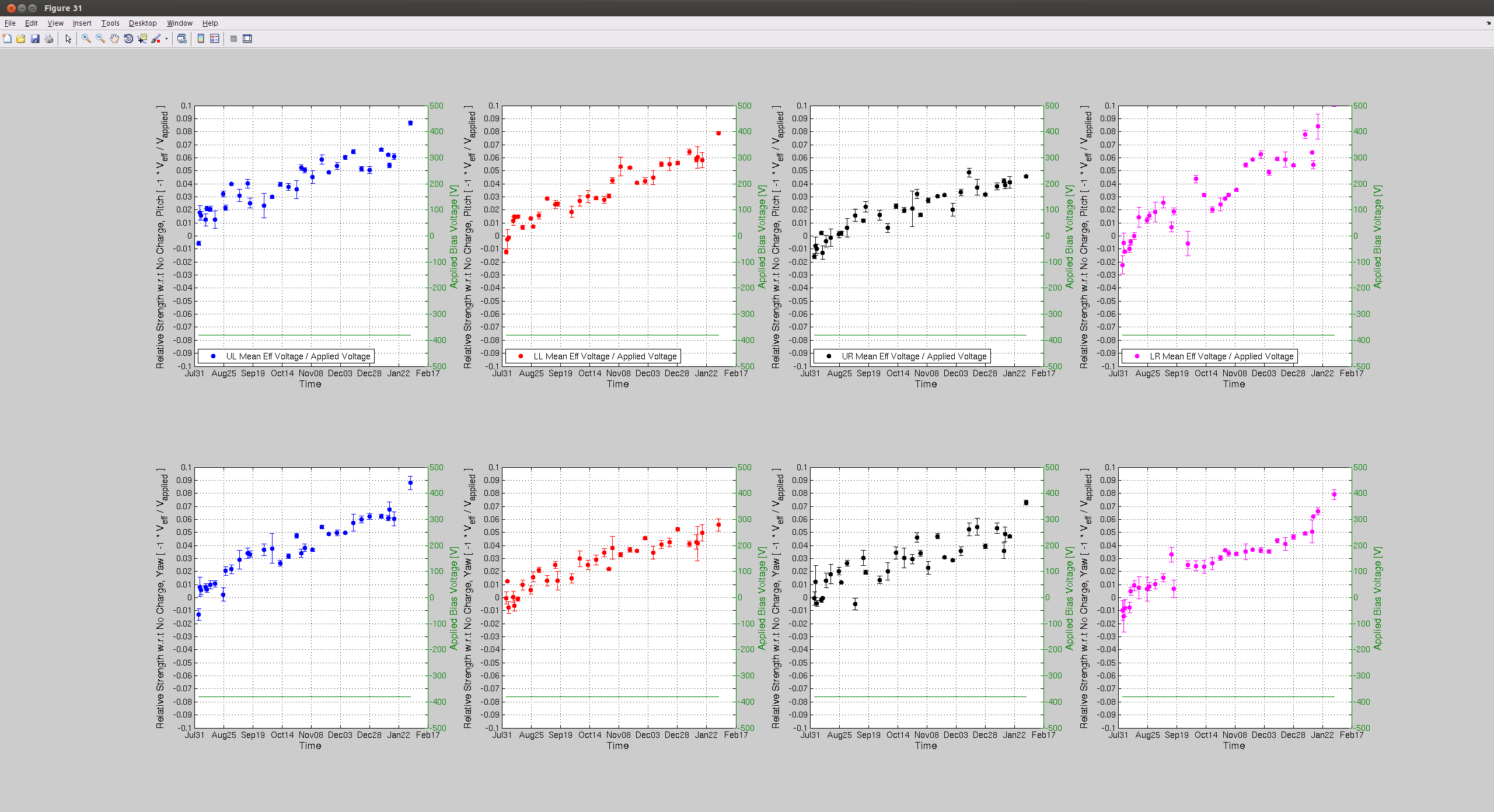
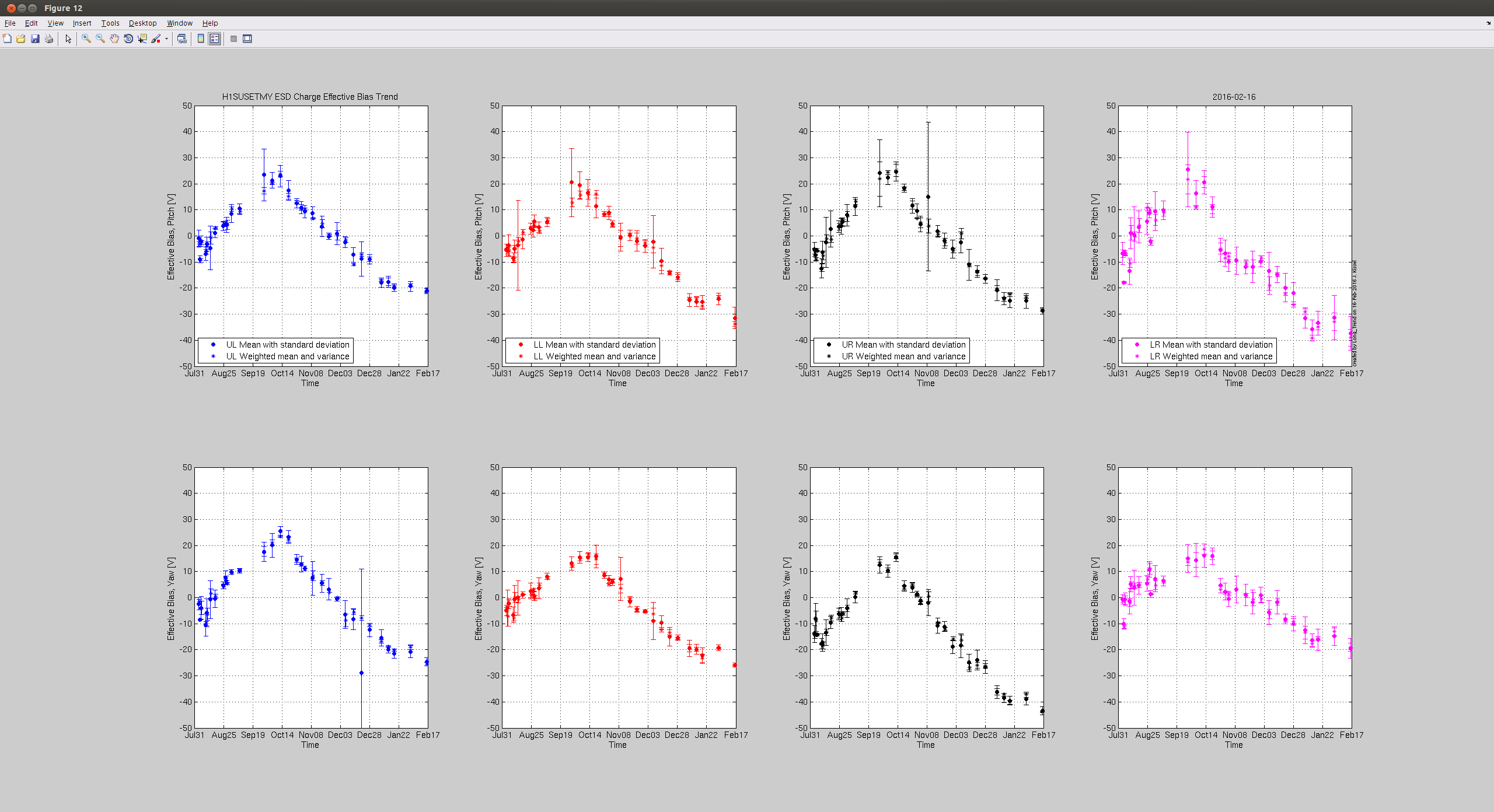
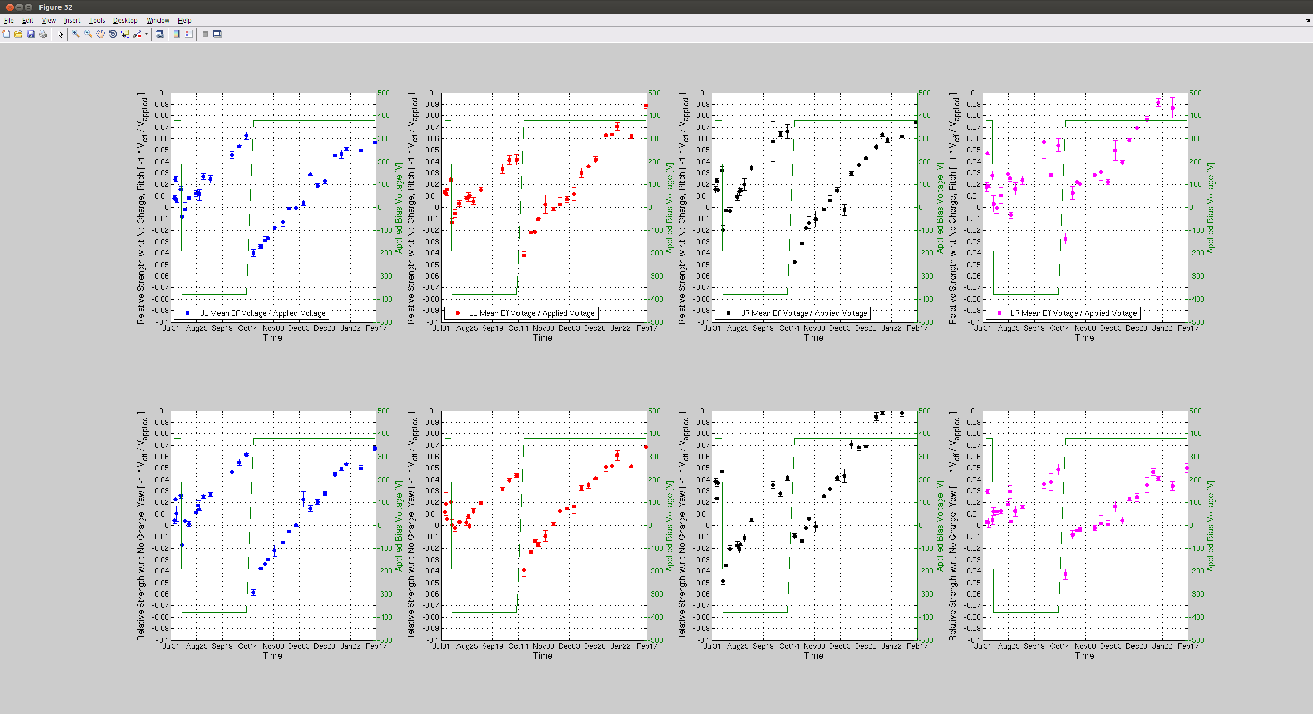
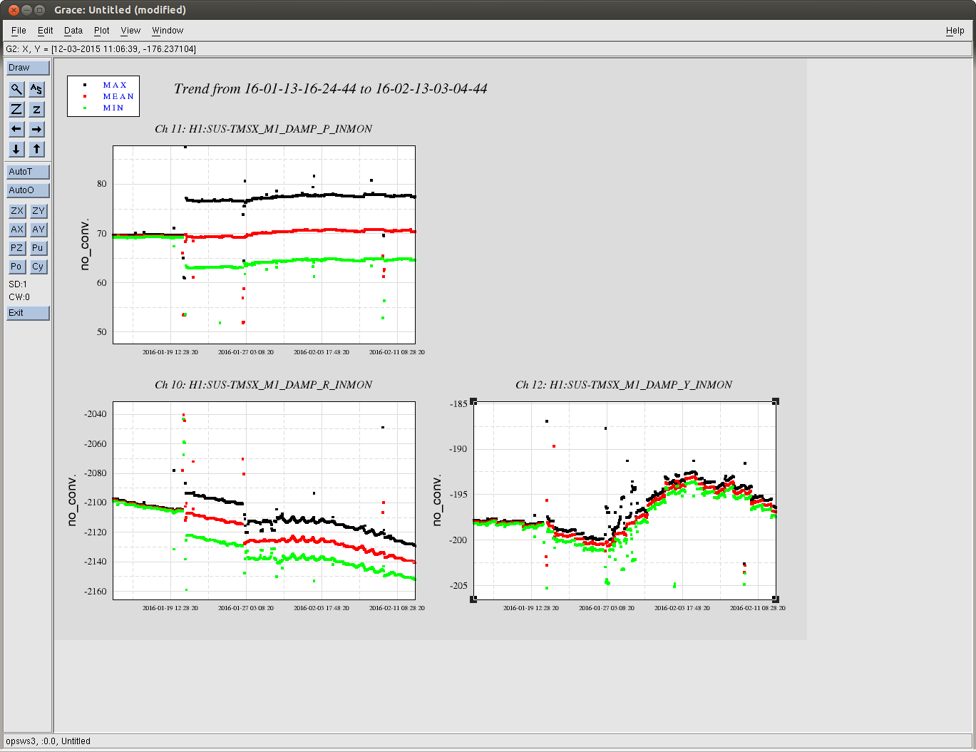
In the first attachment you can see that something happened to the TMS osems on Jan 21st that makes the peak to peak noise increse by more than a factor of 10. This is still the case.
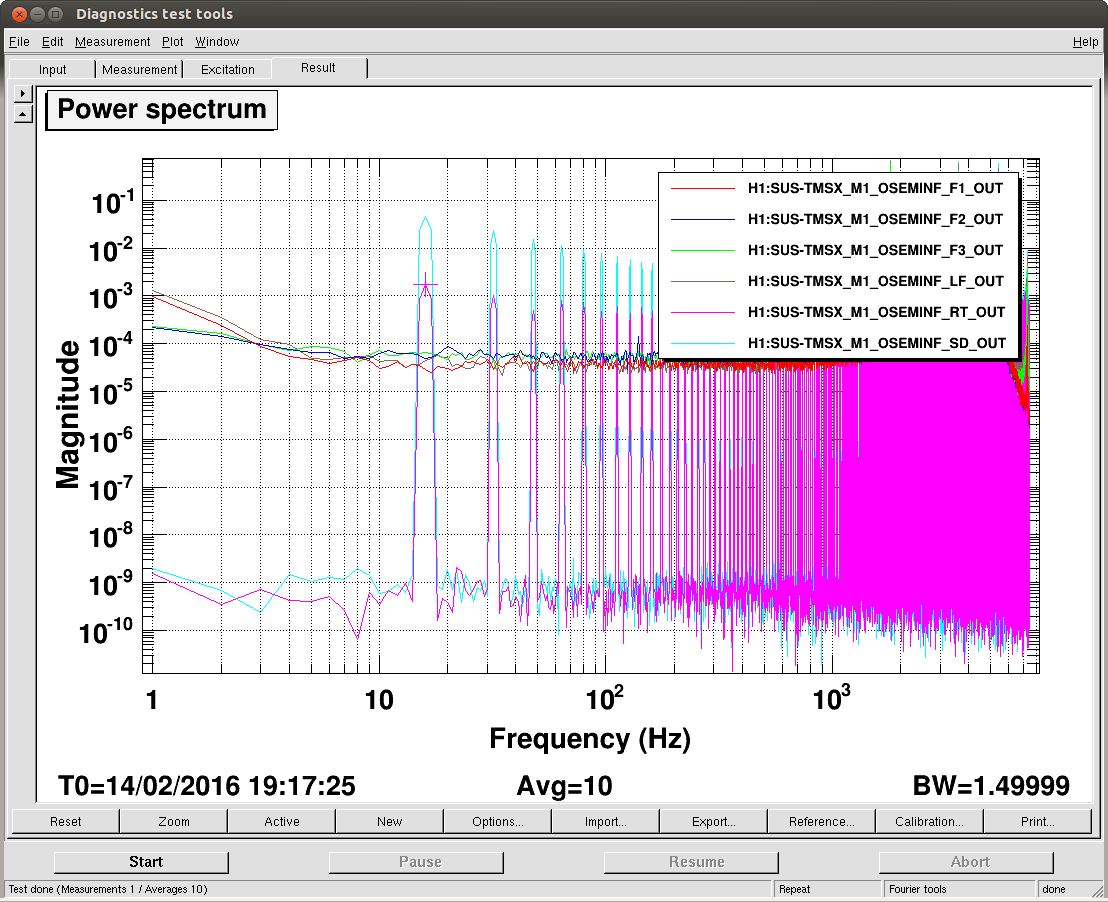
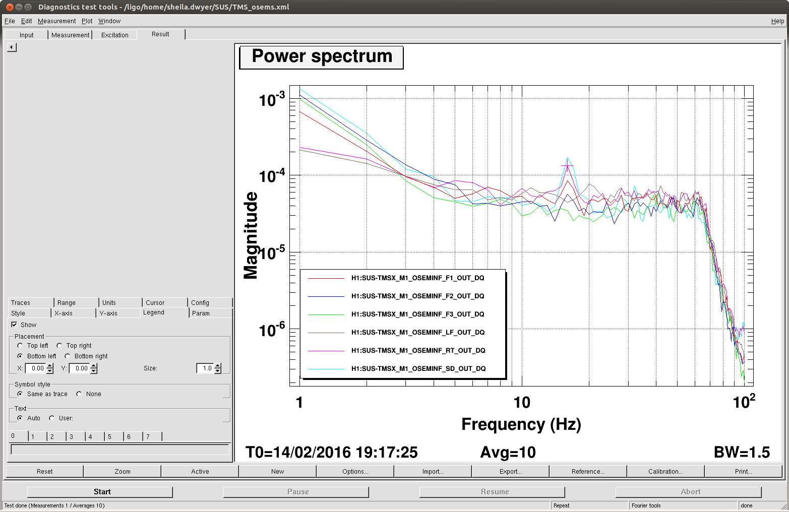
I then took a look at the osem spectra, (the fast channels which are not DQ) and saw a 16 Hz comb in RT and SD (second screenshot). Without saving I re ran the measurement including TMSY channels for comparison, and then saw that the comb appeared to have gone away. Spectra of the 256 Hz DQ channels from the time when I originally saw the 16Hz comb are in the third attachment, there is no comb here.
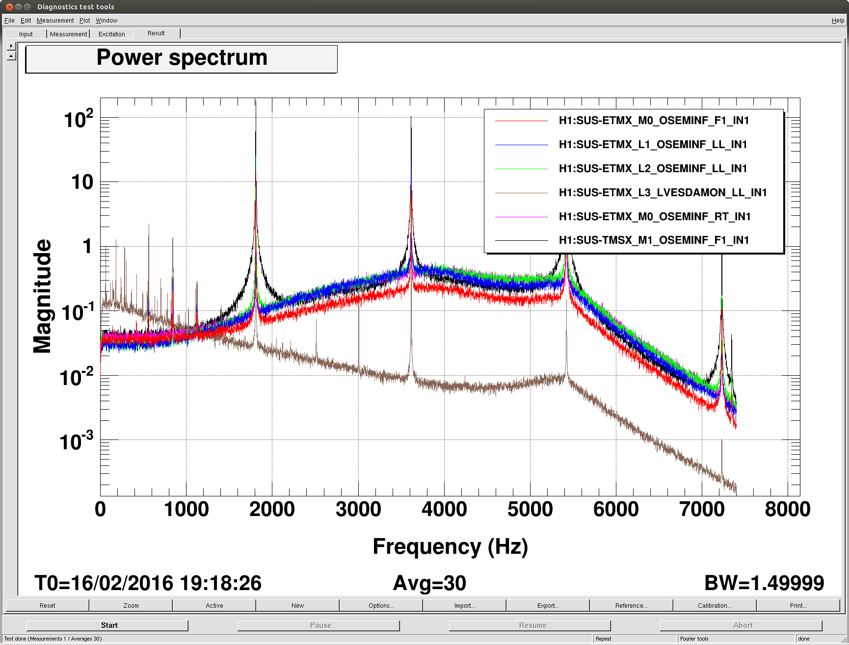
The last attached screenshot shows the osem spectra for both TMSs that I am measureing now, there is some oscillation around 1800 Hz. This is very similar to the behavoir reported in 25062 and 20078
Seems like everything in ETMX chamber is polluted by TMSX OSEM oscillation.
This is an annoyance, some time this week Richard will do the same modification as SR3 mentioned in alog 25516.
{Rana, Evan}
This evening we looked at the coupling of DCPD bias voltage into DARM.
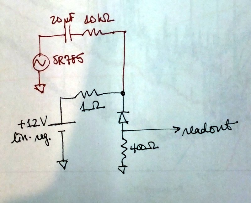
Each DCPD is biased with +12 V from a linear regulator with a 1 Ω output resistor. We wanted to inject extra bias noise, so we exposed the bias lines with a breakout board at the DCPD chassy in the HAM6 rack (see D1300502). Then we summed in the output of an SR785 across an impedance of 10 kΩ in series with 20 µF (see diagram; green shows the normal DCPD electronics and red shows the addition). The 10 kΩ gives a 1:104 ratio of bias fluctuation to drive voltage, and the capacitor ac-couples the drive so that it does not pull on the bias at dc.
With the SR875 we drove a 1 Vpk line first at 187.3 Hz and then at 62.4 Hz (i.e., the bias fluctuation was 70 µV rms). We looked at the response in DARM (at 2 W dc readout, with DARM still controlled by EX). We had 10 mA dc on each PD, in the 400 Ω transimpedance configuration.
For 187.3 Hz (from 02:03:00 to 05:22:00 Z), the magnitude in DARM was 1.13×10⁻¹⁸ m rms, which implies a coupling of 1.6×10⁻¹⁴ m/V. The noise of the regulator at this frequency was 0.9 µV/Hz1/2, which implies a DARM noise of 1.4×10⁻²⁰ m/Hz1/2.
For 62.4 Hz (from 05:33:00 to 05:56:30 Z), the magnitude in DARM was 1.4×10⁻¹⁸ m rms, which implies a coupling of 2.0×10⁻¹⁴ m/V. The noise of the regulator at this frequency was 1.9 µV/Hz1/2, which implies a DARM noise of 3.7×10⁻²⁰ m/Hz1/2. Note that there is some room for error here because the DARM control configuration here is not exactly the same as the low-noise configuration. However, the ugf and phase margin should not be too different in the two configurations.
This is very close to the current low-noise DARM noise floor. However, if DARM is limited by voltage noise of the regulators, we should either expect that the DCPD null stream is equal in magnitude to the DCPD sum (it isn't), or the regulator noises are coherent (they aren't).
I am not sure if there are any contradictions in these numbers. DARM calibration at DC is

C [W / m] = 4 * pi * G_arm / lambda * sqrt(G_prc * P_in * P_as / G_src) = 1.5e9 and 5e9 for input power 2W and 22W and 26mW at the AS port.

This means that the response you measured is ~2e-5 A/V. If the input power is 22W, 1uV/sqHz projects to 4e-21 m/sqHz around 100Hz. This number is what you have in your noise budget plots.
The freerunning DARM channel may not be properly calibrated in the low-power state with EX control, so the numbers I gave originally could be too high.
We directly measured 1.2×10⁻⁶ mA rms in DCPD B at 187.3 Hz, which implies a coupling of 0.017 mA/V, which implies the bias noise shows up in DCPD B at 1.5×10⁻⁸ mA/Hz1/2. The shot noise with 10 mA on the PD is 5.7×10⁻⁸ mA/Hz1/2. So it is a factor of 4 or so below the DARM shot noise, assuming DCPD A is similar. That's close to the dark noise, but the dark noise is flat down to a few tens of hertz while the regulator noise has some negative slope.
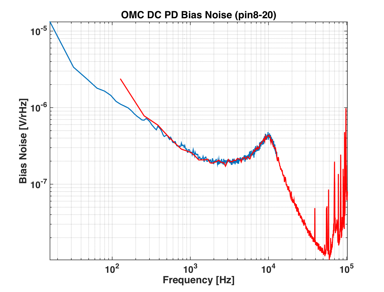
Voltage noise of bias (pin #8 of the d-sub), measured with BNC clip doodle and SR785 (with AC coupling).
Sheila, Rana
We continued the investigation. Today we hooked up a DAC channel to the bias to make sweeps and noise injection. No surprises relative to yesterday. Still seems so close to DARM as to be unbelievable. Maybe the 1 Ohm resistor in the bias circuit is not stuffed?
We also injected random noise into PZT2 to look for upconversion there. We saw the usual kinds of quadratic coupling; noise at a level ~500x above the quiesscent HVmon noise level was able to be just visible in DARM in the baseband as well as by injecting noise close to the 4100 Hz dither frequency.
0554 UTC, leaving it in 'low noise mode'. The BS coil driver is in some mixed low noise state giving us increased DAC noise below 50 Hz, but the noise above there is as good as ever.
Can't get the photodiode D's off the DCC at the moment (outage???), but surely there must be a biga$$ cap (ideally several in ||) from the pd cathode to ground??
Yes, in the in-vacuum preamp, there is a 1 uF capacitor from the Bias to ground. At the LM317T (voltage regulator that sets the bias), there is a 10 uF cap to ground, on the regulator side of the 1 ohm resistor (it's not shown in Rana's sketch above). In any case, the projection given above relies on the 1e4:1 scaling of the injected signal - can't you just measure directly the drive on the bias line, rather than assuming the 1e4:1 ratio?
Bigger caps are unlikely to help much. The noise is due to the internal burried zener diode which serves as the voltage reference. The BW of the regulator is about 10kHz here. A bigger C may reduce this, but may also increase gain peaking. Just use a low noise supply such as the one here. Noise performance: T1000025.
Den, Rana
We directly measured the voltage noise on pin8 and confirmed that our injection through the 9.09k resistor (not 10k as indicated above) scales as expected. It seems that the 1 Ohm resistor is really 1 Ohm (+/- 20%).
From MZ, we have http://www.edn.com/electrical-engineer-community/industry-blog/4422750/2/Simple-circuits-reduce-regulator-noise-floor.
This indicates that some larger caps may reduce the regulator output noise at 100 Hz by a factor of 5 or so. Could be easy to try if we have a spare whitening chassis sitting around.
Rana, Sheila, Den

We have measured the bias noise with a better resolution and found that this noise is almost flat below 60Hz. Then made a projection of this noise to DARM when the input power was 22W and power on each OMC PD was 10mAmps. For PD A the coupling is 1.5e-15 m/V while for PD B is 3e-15 m/V. Attached plot shows the projection of bias noise to DARM. It is factor of ~4 below the current sensitivity.
According to the noise budget and measurement of the dark noise, this noise is above the dark noise level. This means that the noise is present only when the DC photocurrent is present.
Suggests QE compression due to bias reduction. For higher P it may be wise to not only improve bias voltage noise, but to fix anode-cathode potential. Either a true transimpedance
preamp, or a tracking supply at the rack.
We drove PD_B bias and measured the coupling of the bias noise to OMC NULL channel for different current levels. Plot is attached.

The coupling is close to zero when there is no power. The coupling scales linear for small currents and stays almost constant for large currents (>10mA on each diode).

We have also double checked that the optical signal scales linear with the current by driving an intensity line.
Kiwamu, Den

We have digitized bias channels (LSC:EXTRA_AI_2 channel) and double checked coupling to DARM. Attached plots show coupling of PD_B bias to DARM. There is a calibration line at 62.4Hz of this coupling.

