Upgrade end station SUS front end computers with faster models [WP5728]
Robert, Carlos, Hugh, Dave, Jim:
The front end computers h1susex and h1susey were upgraded to the faster models. A brand new IRIG-B card which was installed in h1susey did not function correctly, and the card from the old computer was used instead. At both end stations the swap caused the other machines on the Dolphin fabric to hang, and therefore all models on h1seie[x,y] and h1isce[x,y] were restarted. The IRIG-B time on h1iopsusey dipped below zero for a short time (giving bad DAQ data and IPC receive errors). On h1iopsusex there was no IRIG-B time slew.
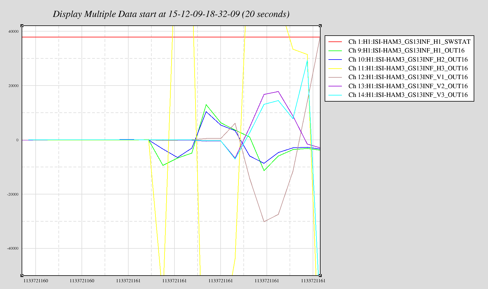
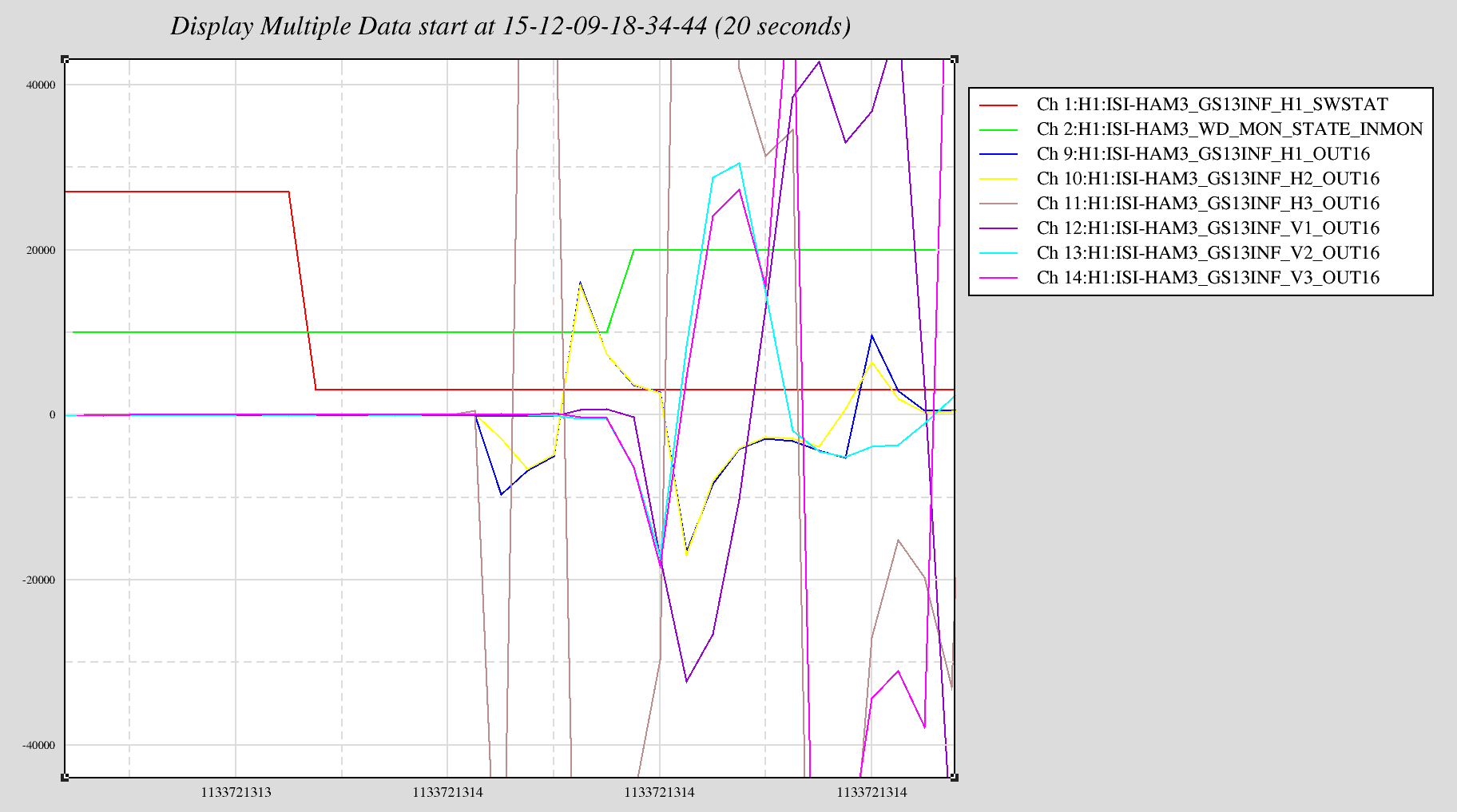
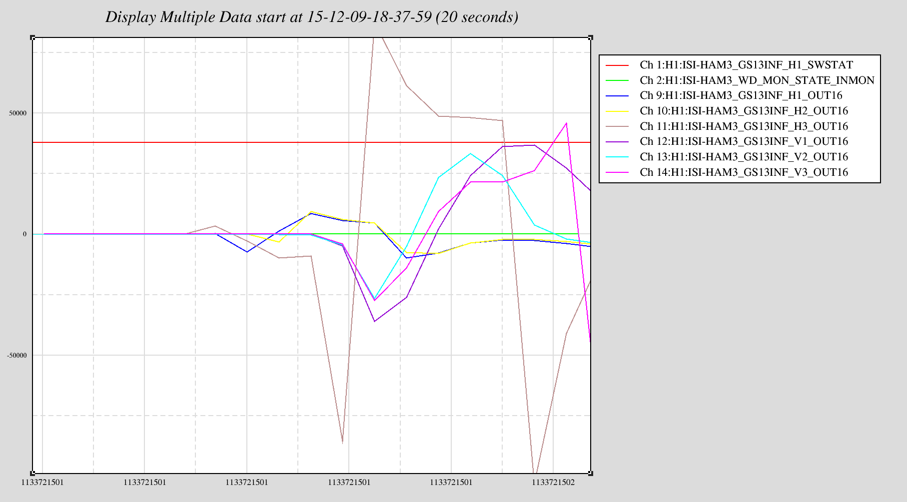
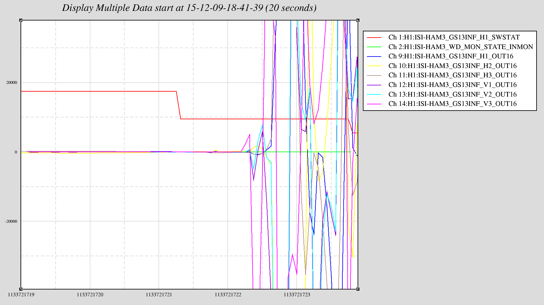
Hugh investigated the ISI payload watchdog as we tried to get SEI to ride through the SUS outage. We found several interesting things about this watchdog, and the main message was that it is not possible to bypass this watchdog before the sus mode is stopped. Turns out this was moot anyhow, since when the sus computer was powered back up the Dolphin fabric was disrupted.
All models were set back to OBSERVE sdf reference. The PEM ADC spare channels which were activated yesterday for Robert went back to their inactive SAFE state, using OBSESRVE state and REVERT I re-activated these.
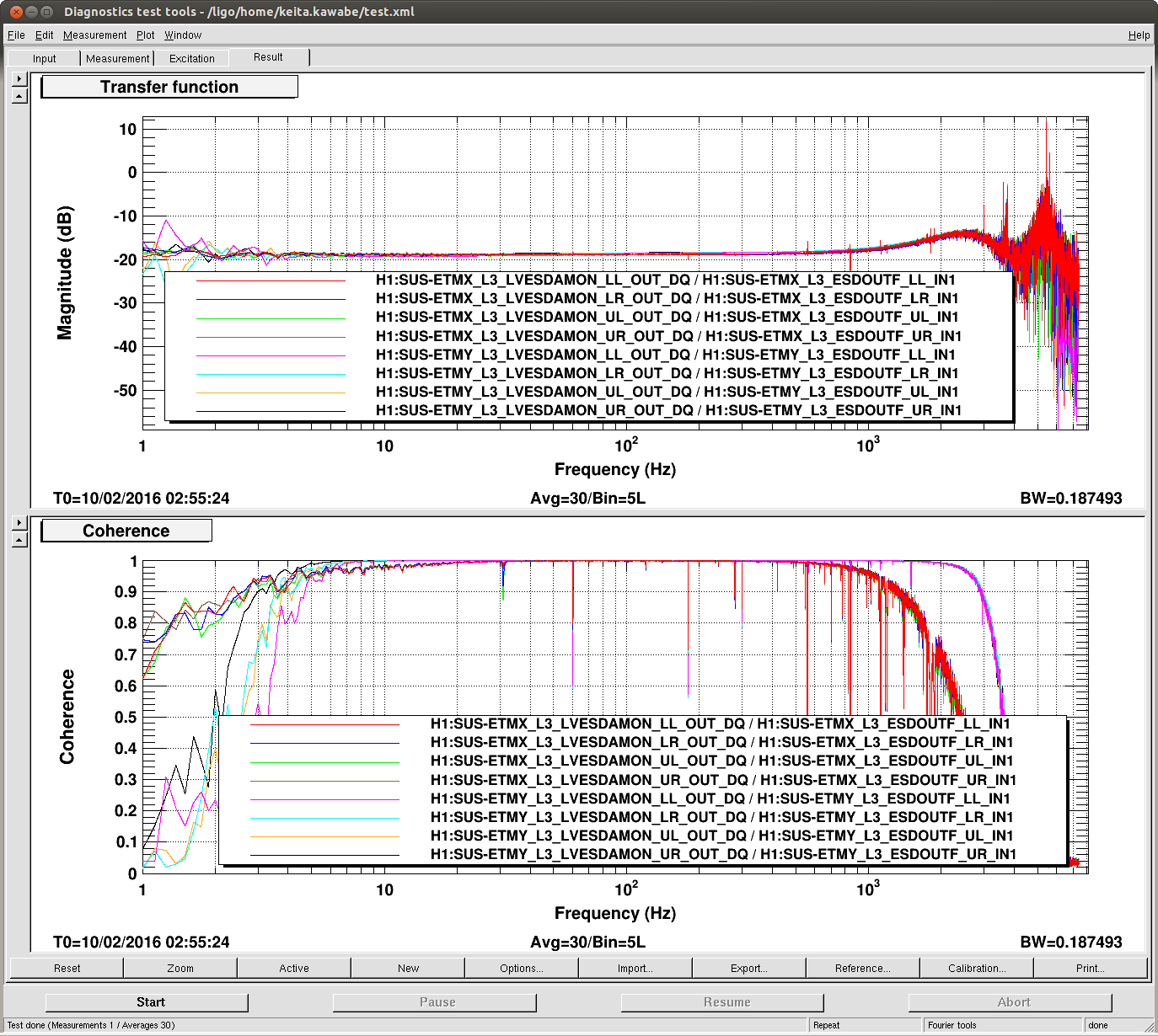
With the faster computer and the original 2.6 kernel comes the periodic timing and adc errors on the sus machines. Since these errors usually latch on until a DIAG_RESET is issued, I am running a script on opsws16 which presses the DIAG_RESET button every minute on h1iopsuse[x,y] and h1susetm[x,y]. This will permit trending of these errors.
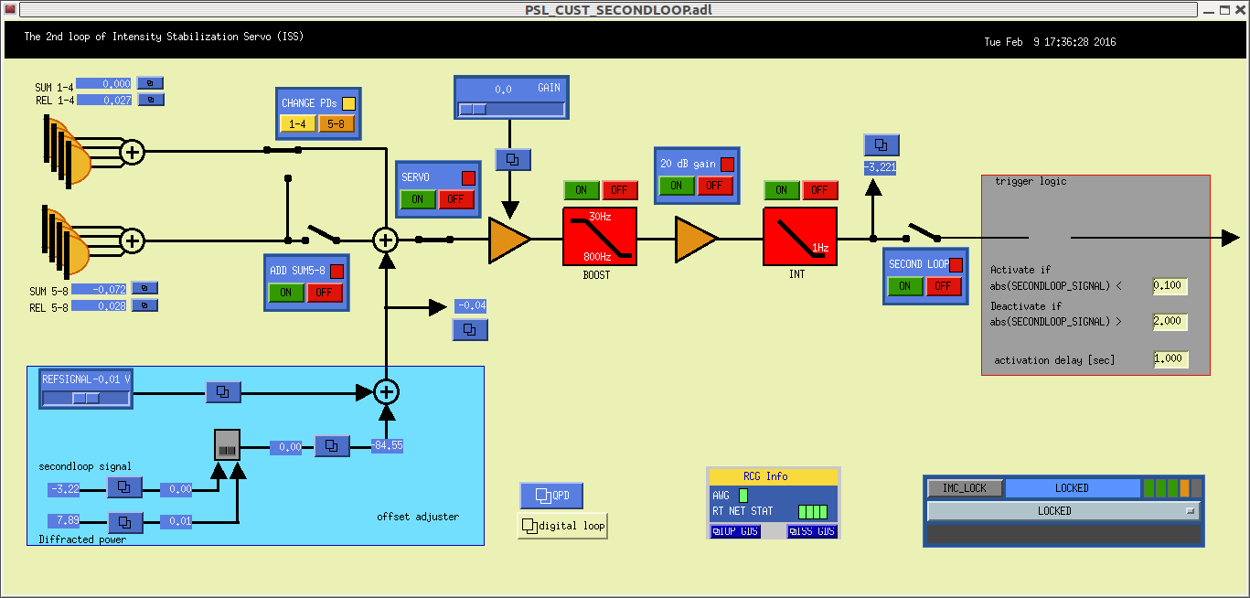
New PSL ISS model
Dave, Kiwamu:
Kiwamu installed his latest h1psliss model, this required a DAQ restart
New Beckhoff corner station PLC2 code
Daniel, Dave, Patrick:
Patrick installed new h1ecatc1plc2 code. I updated the DAQ INI and autoburt.req files. This required a DAQ restart
DAQ restart
Jim, Dave:
We restarted the DAQ once today for the above changes. The restart was clean. One interesting note is that h1fw0 started sufficiently before h1fw1 that it wrote our a full frame before h1fw1 got going.
Conlog
Dave, Jim, Patrick
After the autoburt .req file was regenerated, Patrick rescan the conlog channels. On restart he found that LAB DUST channels were missing. Jim tracked it down to a crashed IOC and restarted it.
SVN code cleanup
Dave:
I ran my ''check_h1_files_svn_status'' and committed all outstanding modifications. This resulted in updates for: front end mdl file (h1psliss), many filter files, many SAFE SDF snap files, many OBSERVE SDF snap files, many Guardian python scripts.
Partial filter loads full loaded
Dave:
I performed a full filter load on the two models which were running with possible partial loads: h1psliss, h1susitmy