Edgard, Oli.
Follow up to the work summarized in 84012 and 84041.
TL;DR: Oli tested the estimator on Friday and found the ISI state affects the stability of the scheme, plus a gain error in my fits from 84041. The two issues were corrected and the intended estimator drives look normal (promising, even) now. The official test will happen later, depending on HAM1 suspension work.
____
Oli tested the OSEM estimator damping on SR3 on Friday and immediately found two issues to debug:
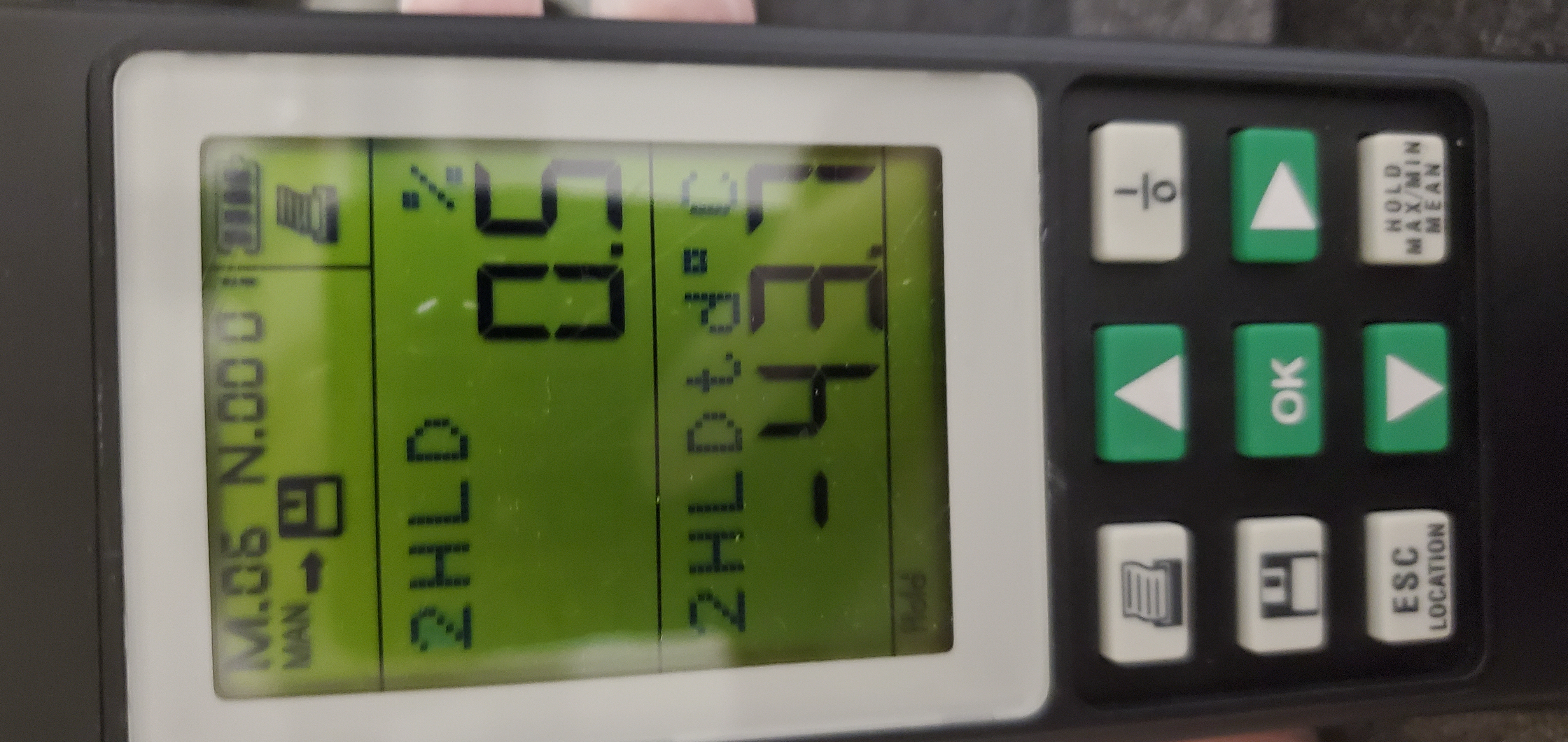
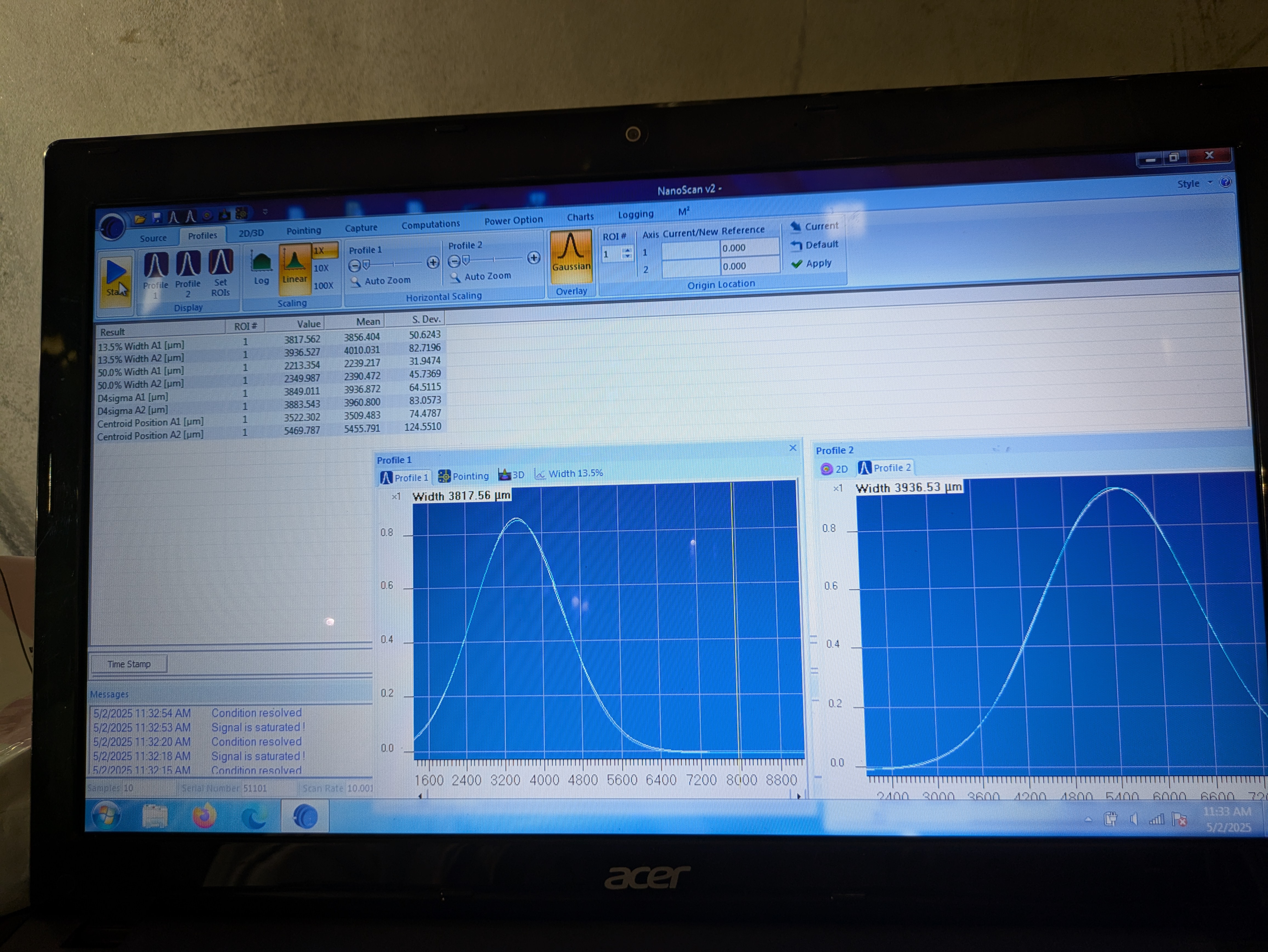
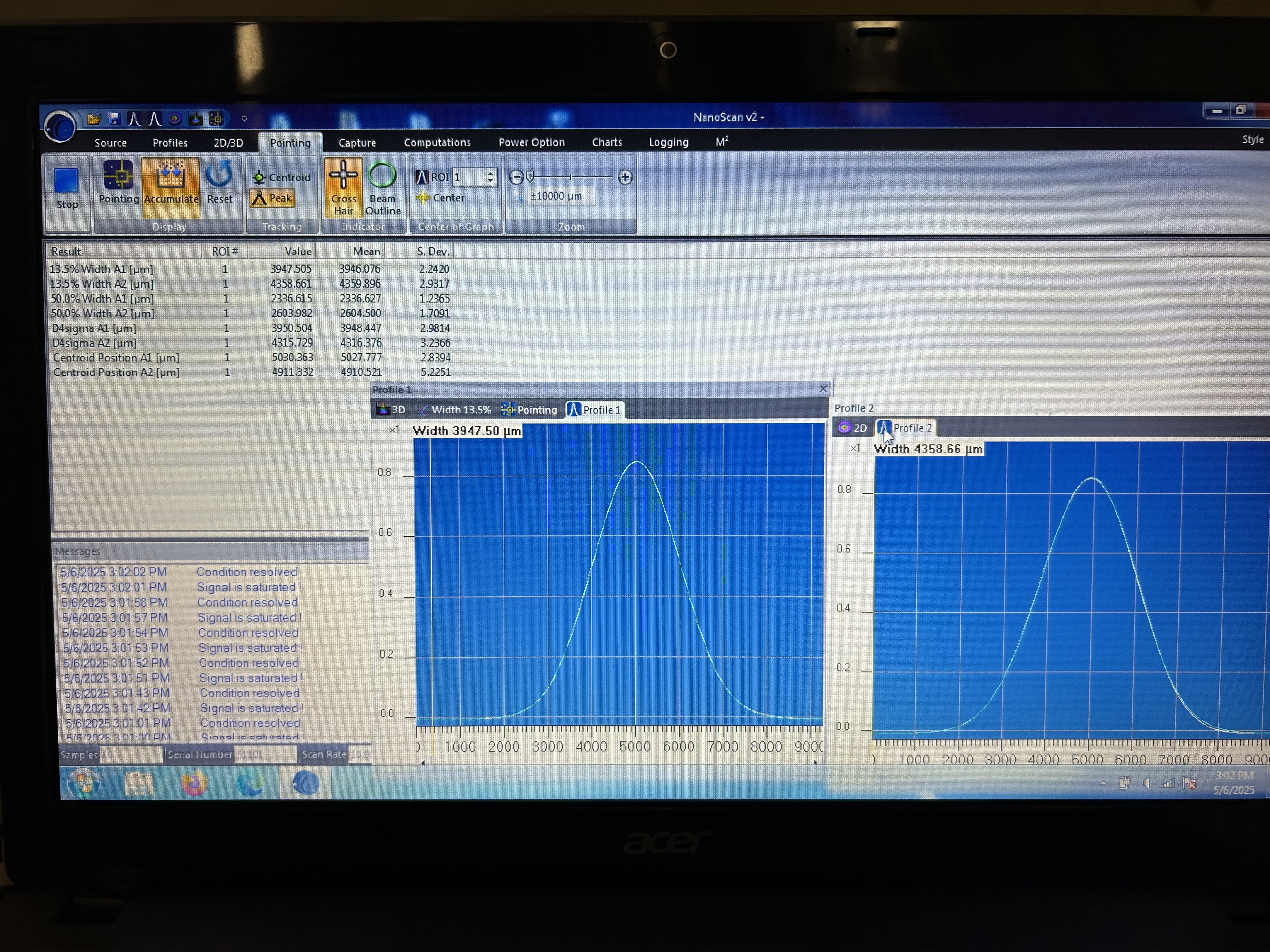
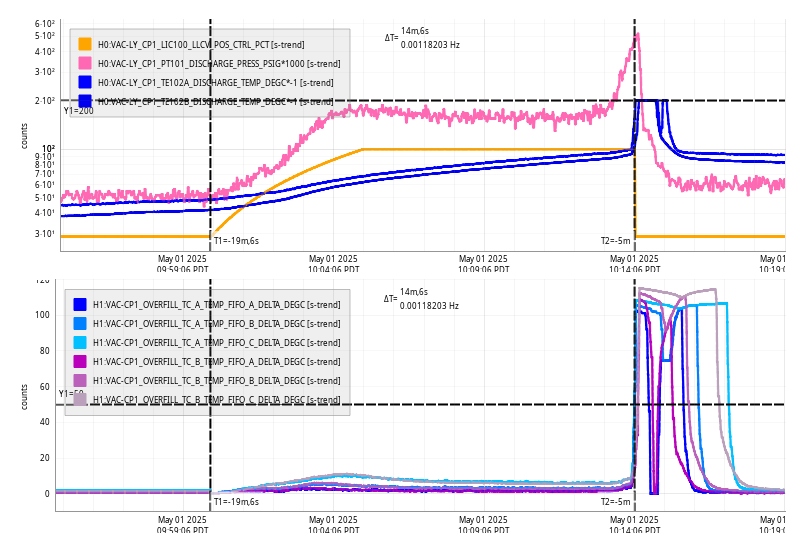
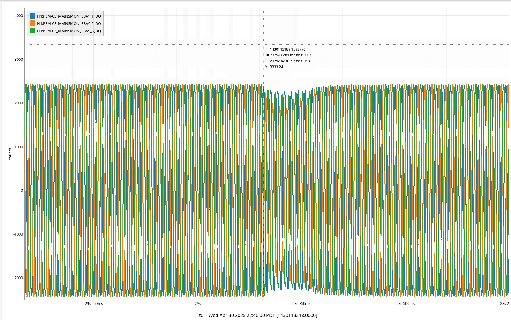
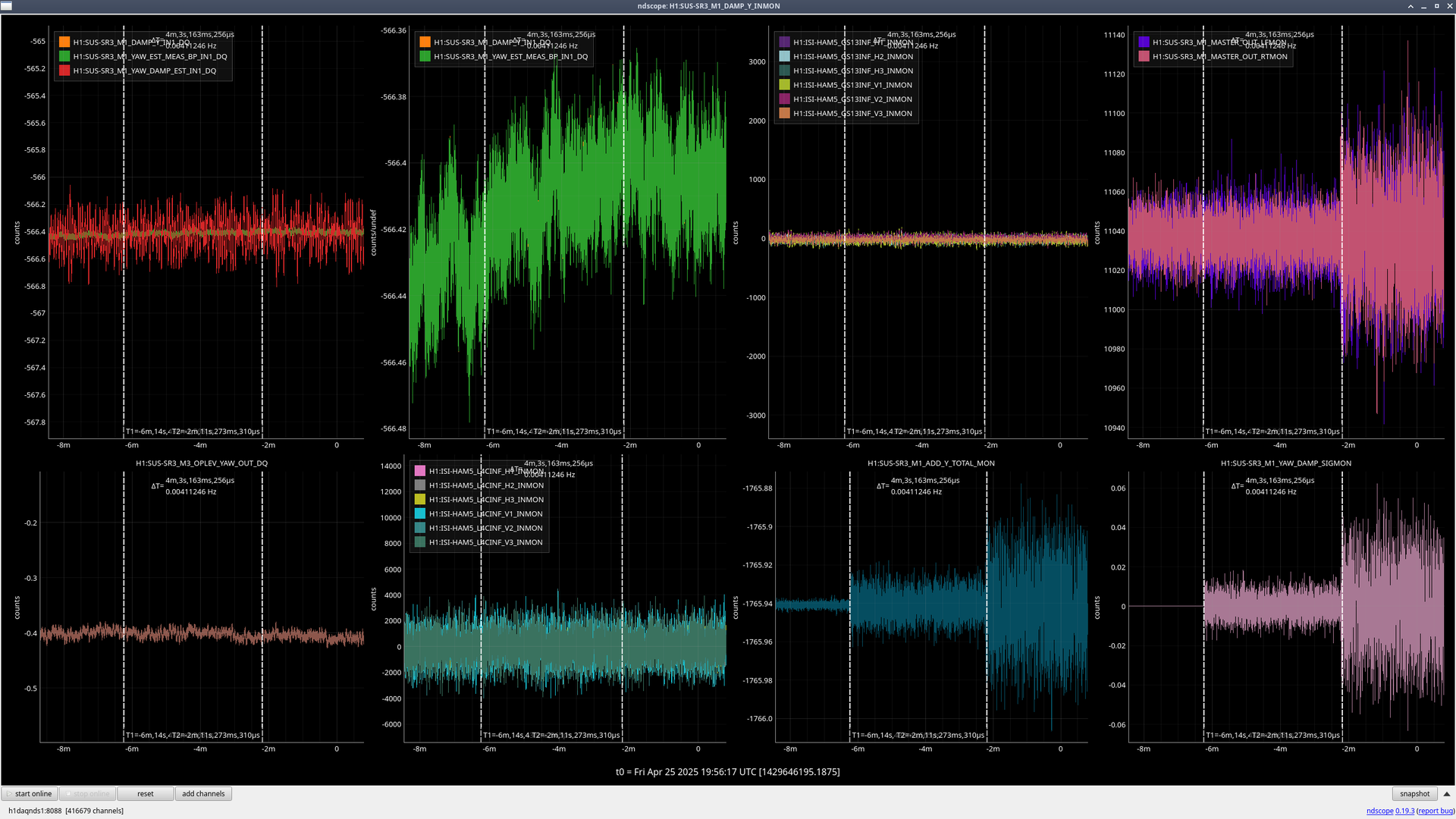
1) [See first attachment] The ISI state for the first test that Oli ran was DAMPED. Since the estimator was created with the ISI in ISOLATED (and it is intended to be used in that state), the system went unstable. This issue is exacerbated by point 2) below. This means that we need to properly manage the interaction of the estimator with guardian and any watchdogs to ensure the estimator is never engaged if the ISI trips.
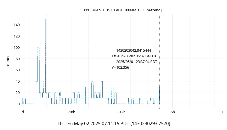
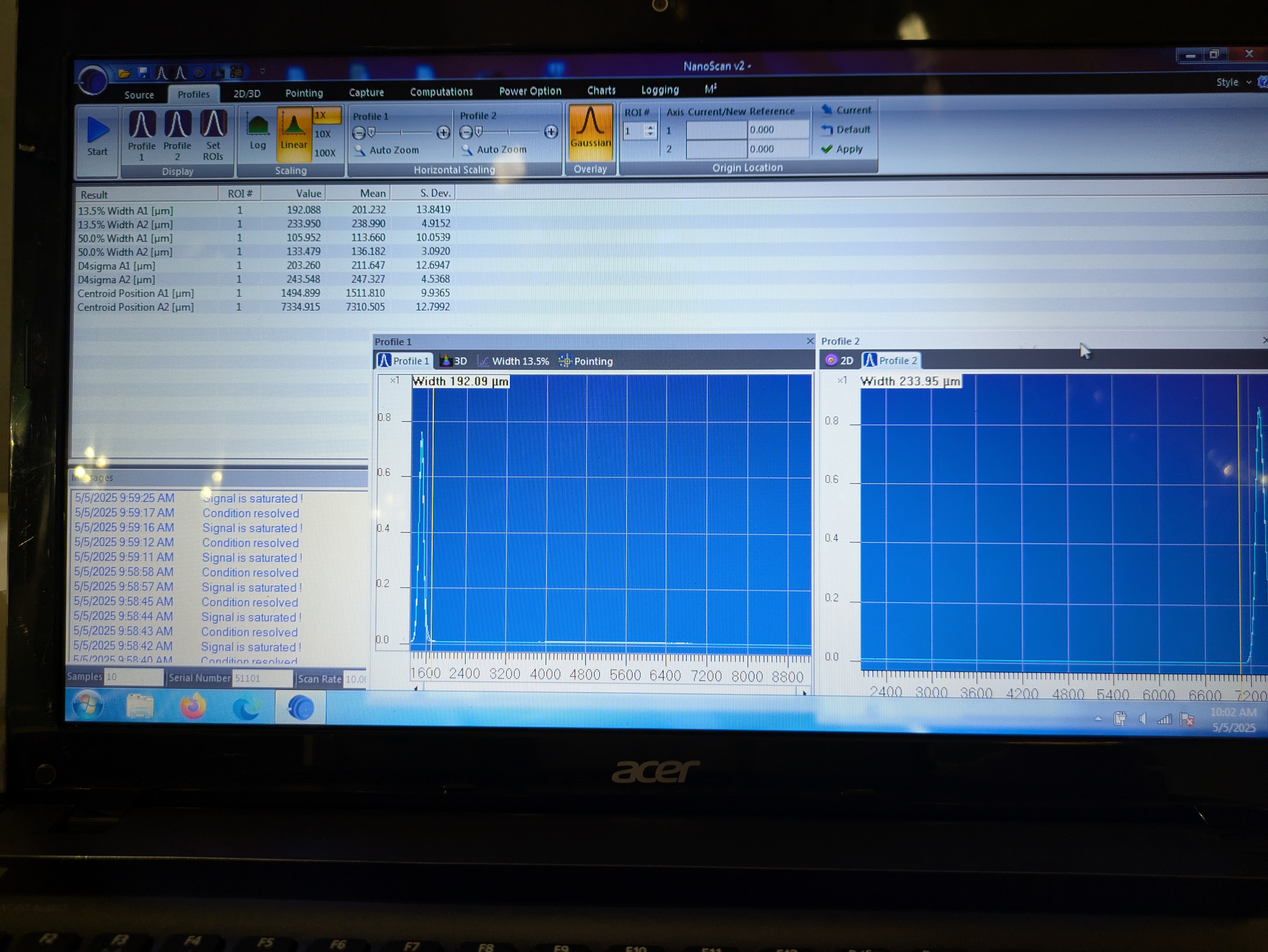
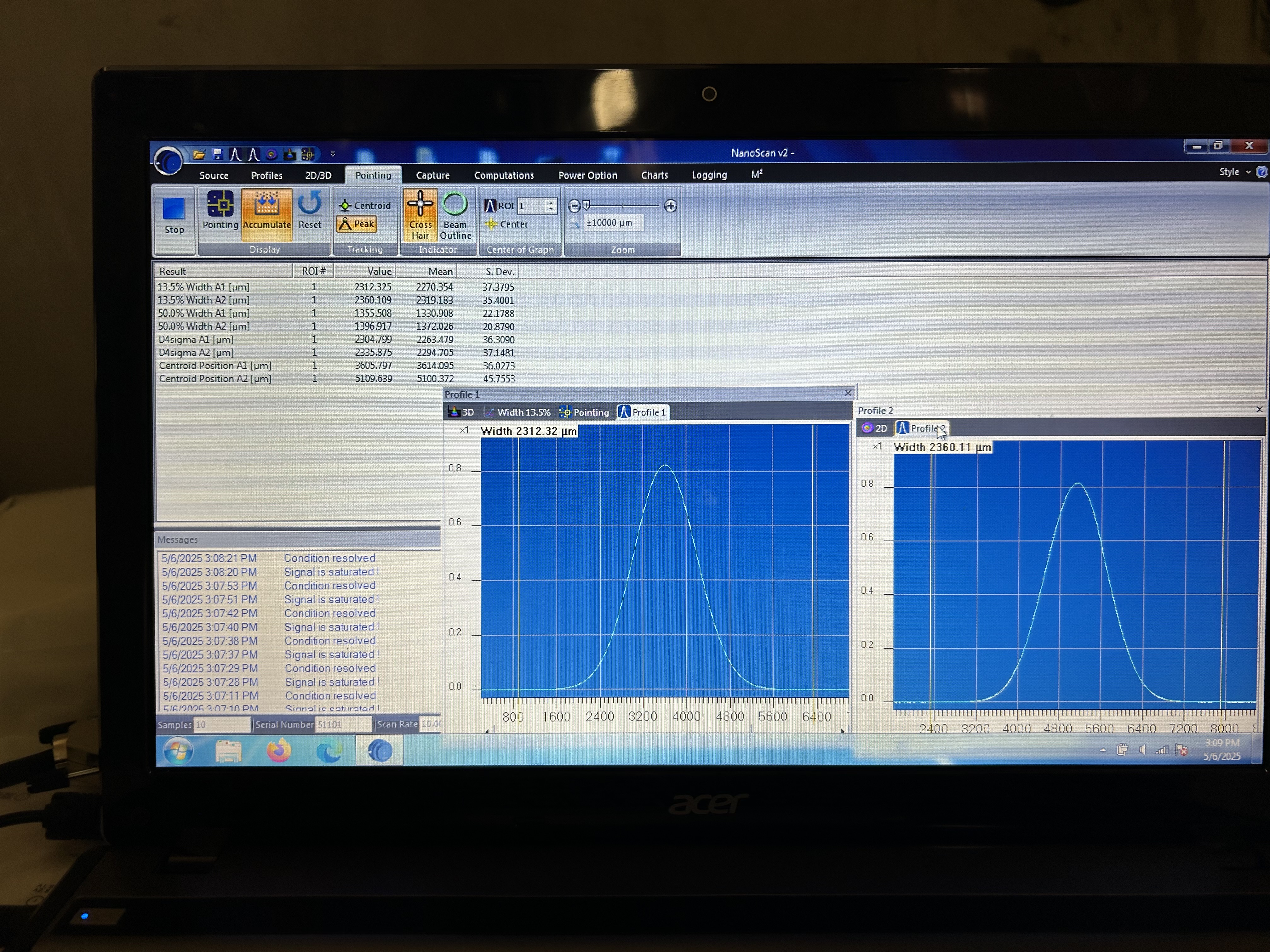
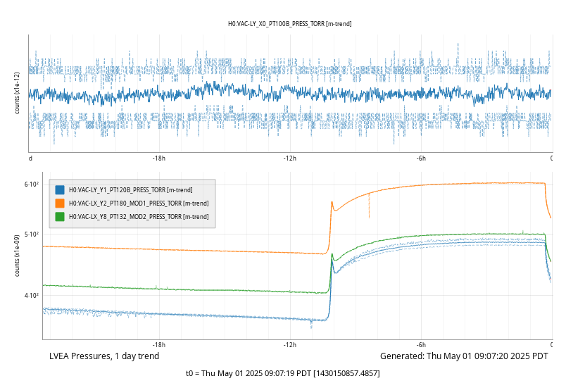
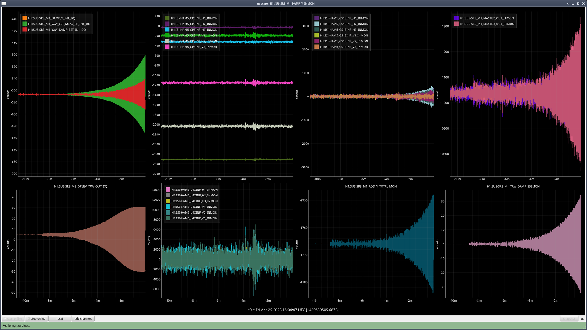
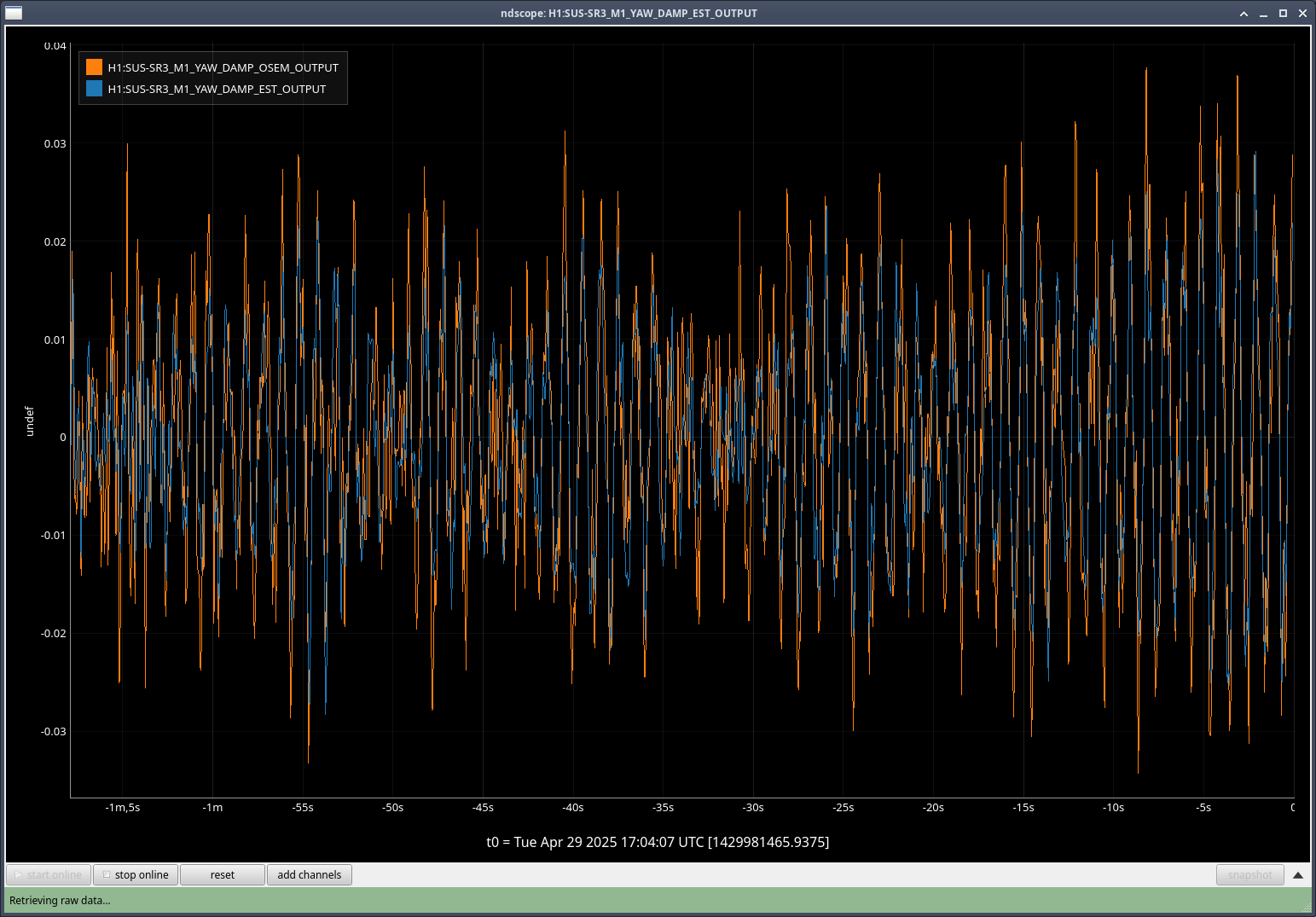
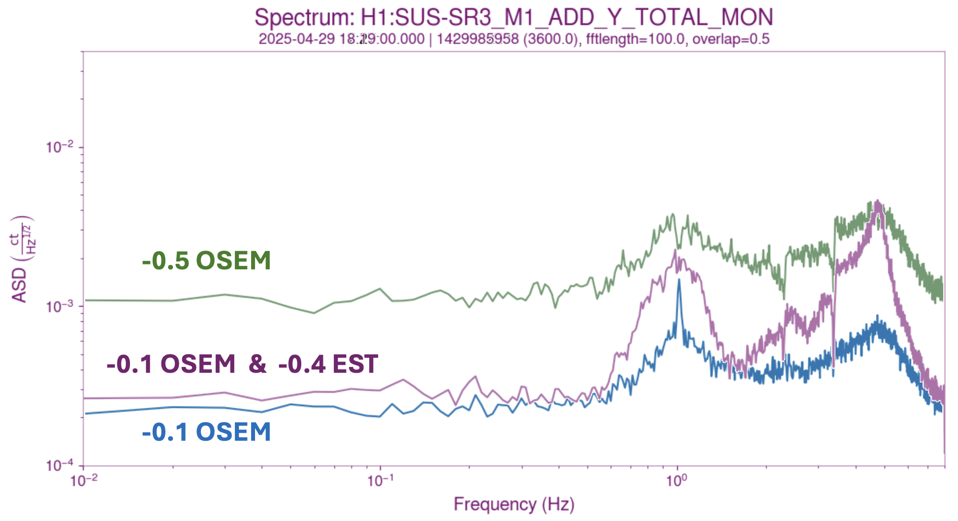
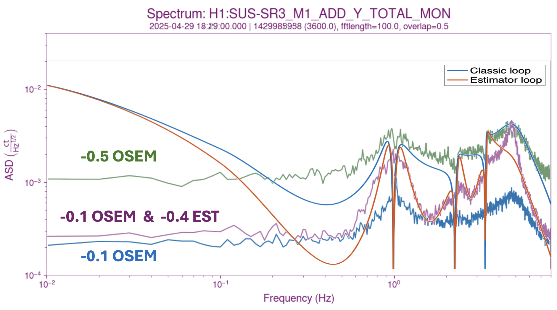
2) [See second attachment] There was a miscalibration of the fits I originally imported to the front-end. This resulted in large drives when using the estimator path. In the second figure, there are three conditions for the yaw damping of SR3:
( t < -6 min ) OSEM damping with gain of -0.1.
( -6 min< t < -2 min) OSEM damping with a gain of -0.5, split between the usual damping path and the estimator path.
( -2 min < t < 0 min) OSEM + Estimator damping.
The top left corner plot shows the observed motion from every path. It can be seen that M1_YAW_DAMP_EST_IN1 (the input to the estimator damping filters) is orders of magnitude larger than M1_DAMP_IN1 (the imput to the regular OSEM damping filters).
The issue was that I fit and exported the transfer functions in SI units, [m/m] for the suspoint to M1, and [m/N] for M1 to M1. I didn't export the calibration factors to convert to [um/nm] and [um/drive_cts], respectively.
____
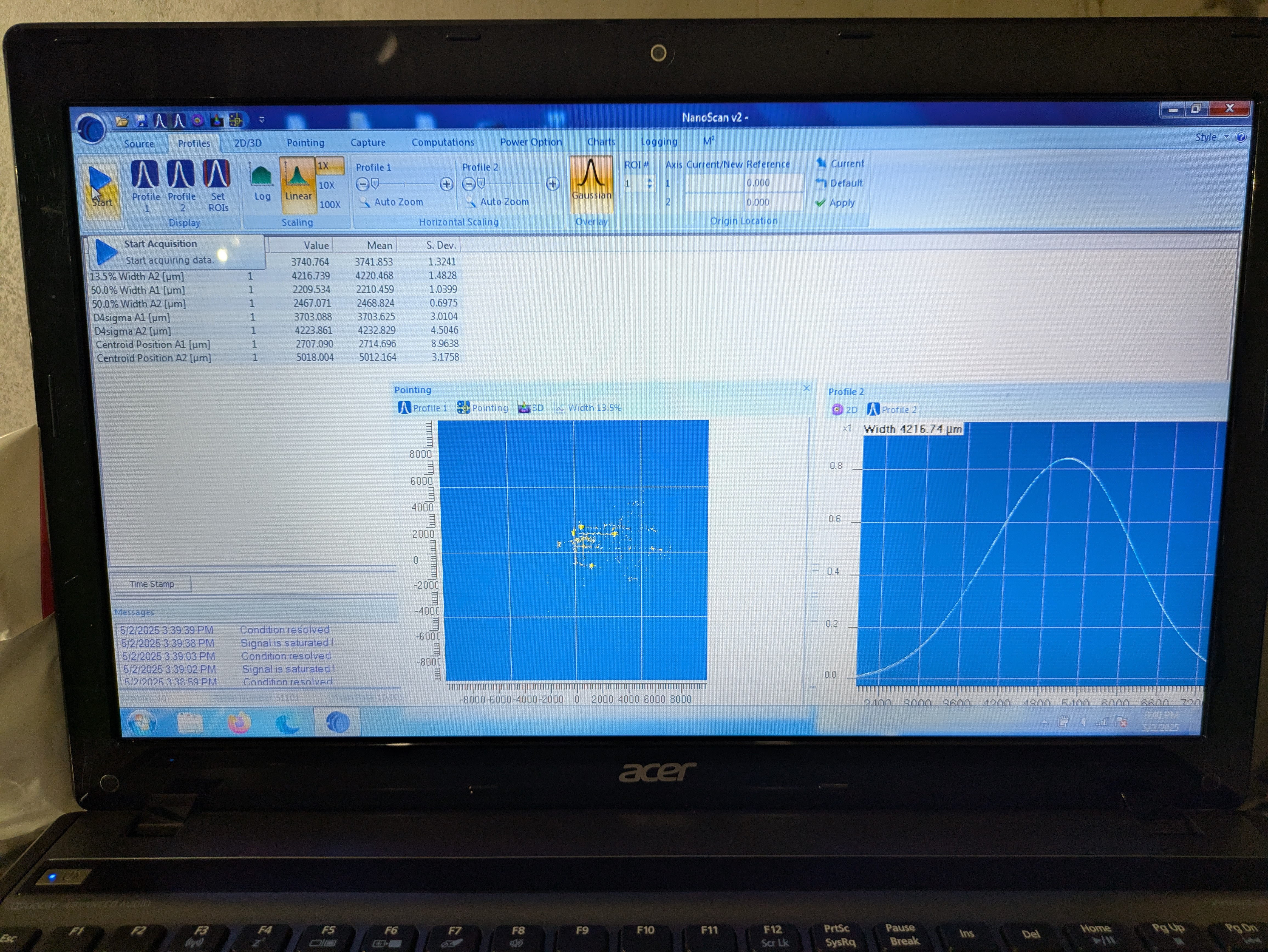
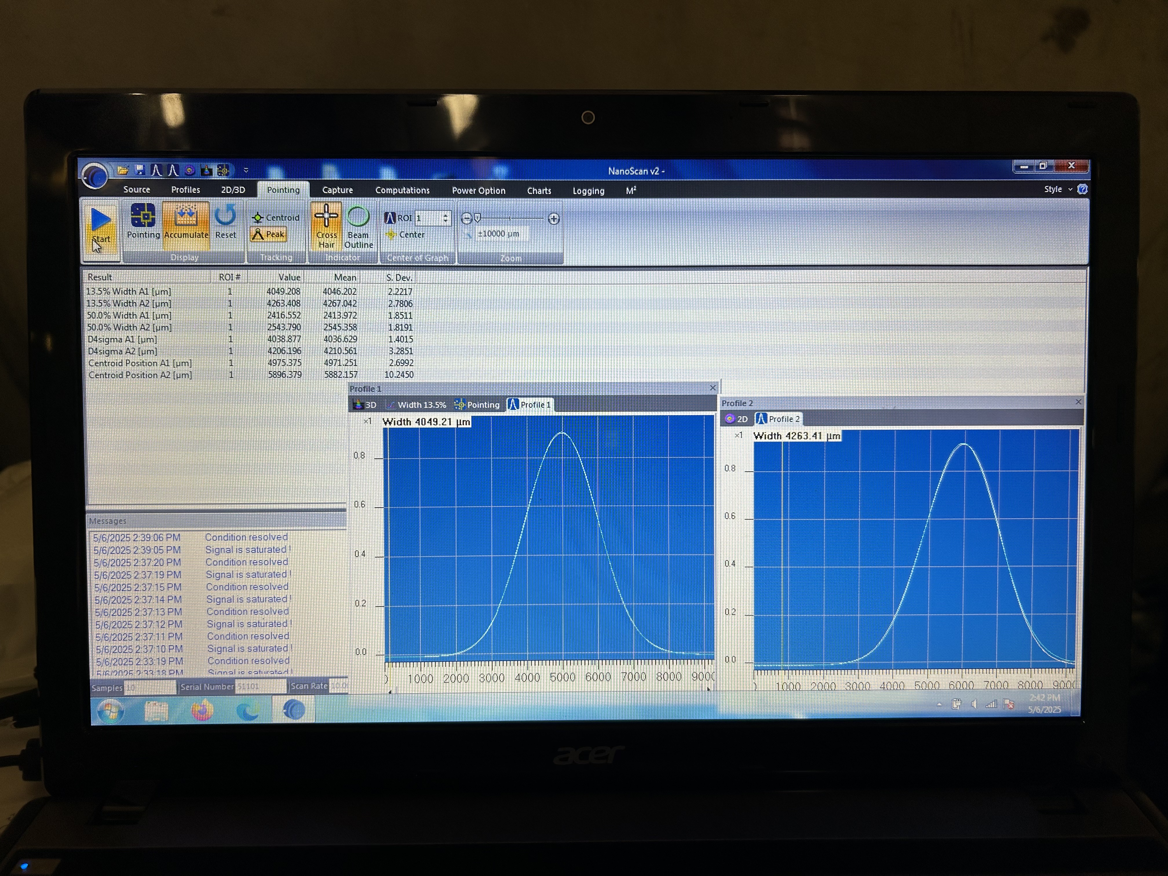
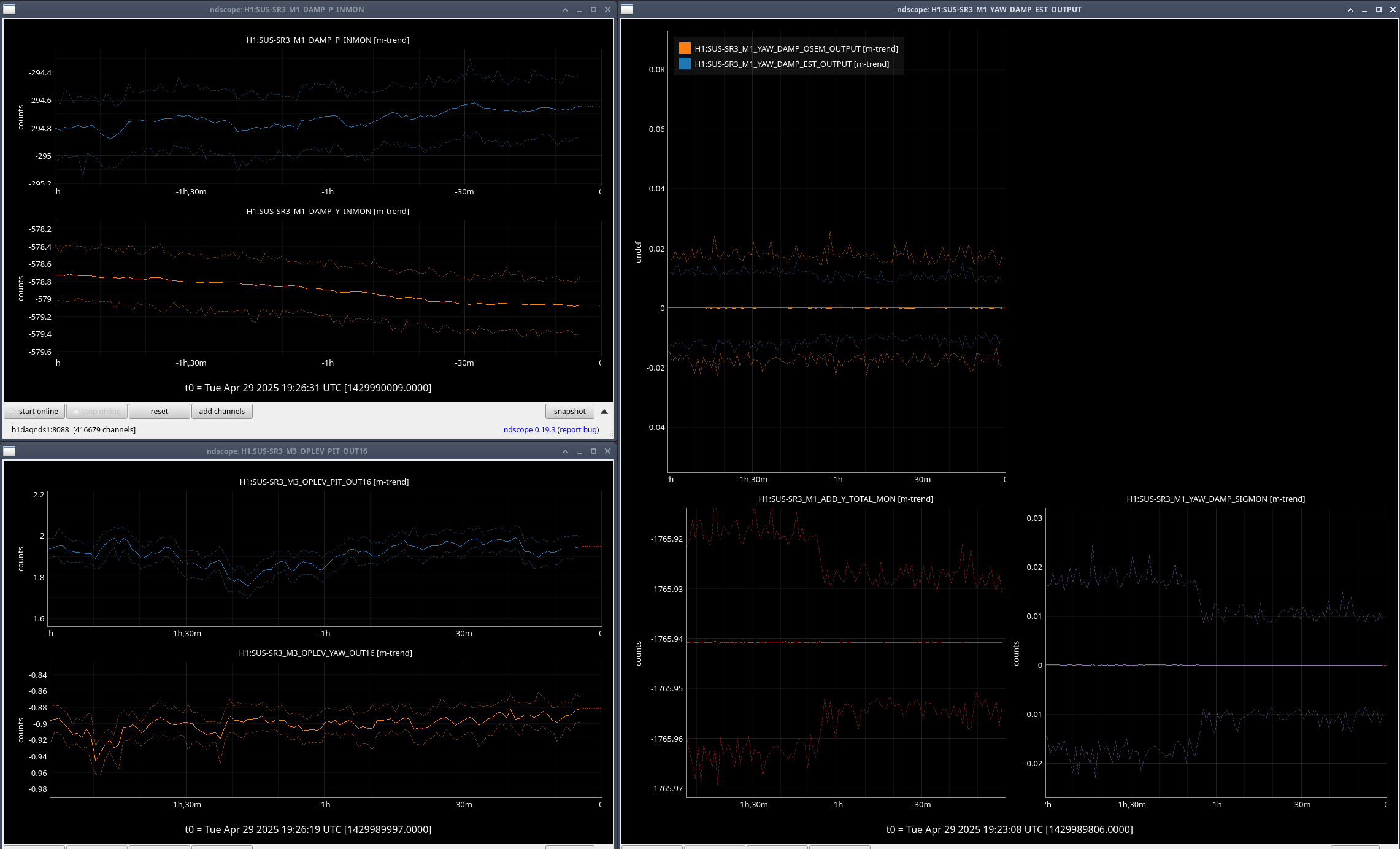
I fixed this issue on Friday. Updated the files in /sus/trunk/HLTS/Common/FilterDesign/Estimator/ to add a calibration filter module to the two estimator paths (a factor of 0.001 for suspoint to M1, and 1.5404 for M1 to M1). The changes are current as of revision 12288 of the sus svn.
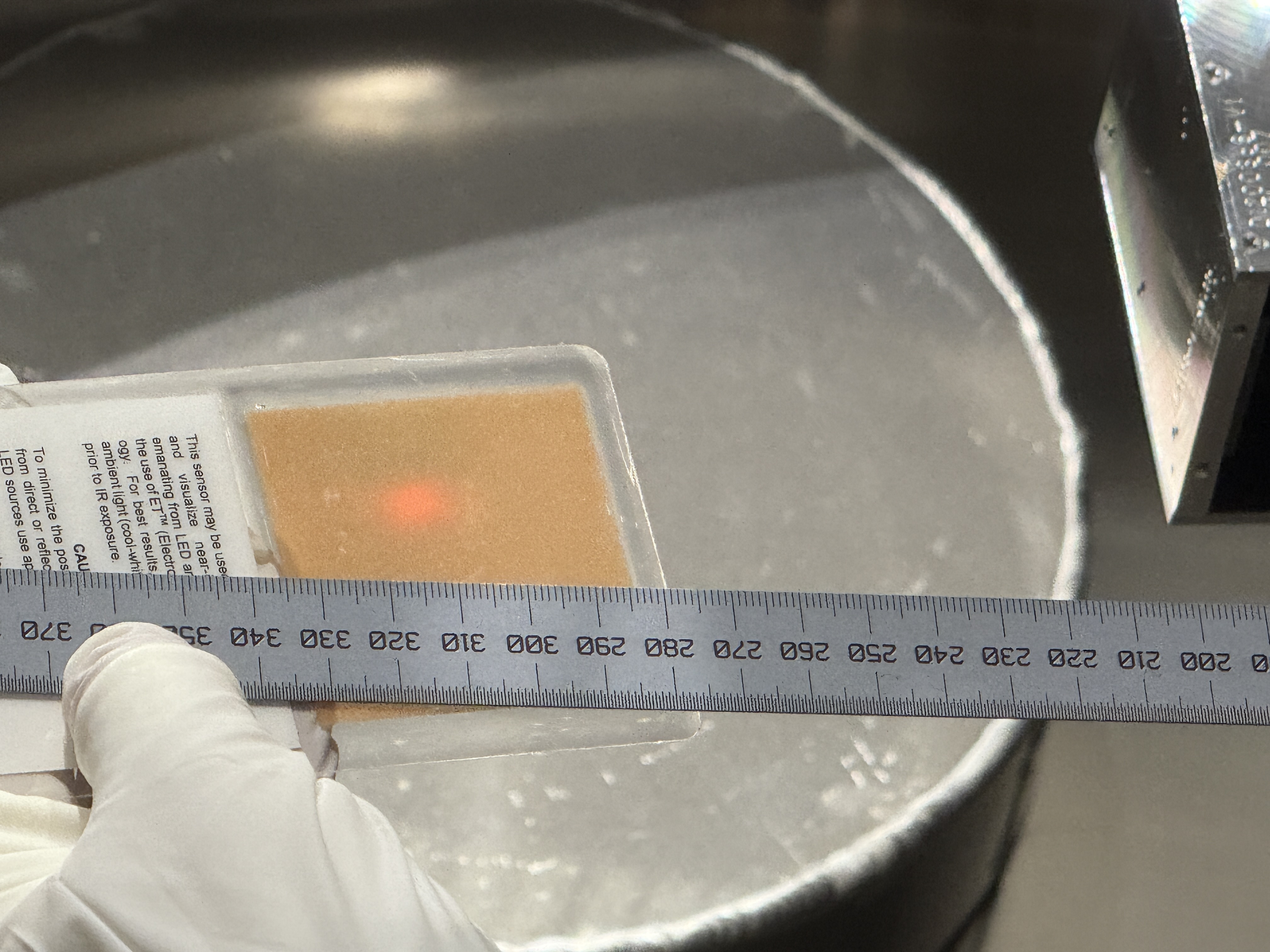
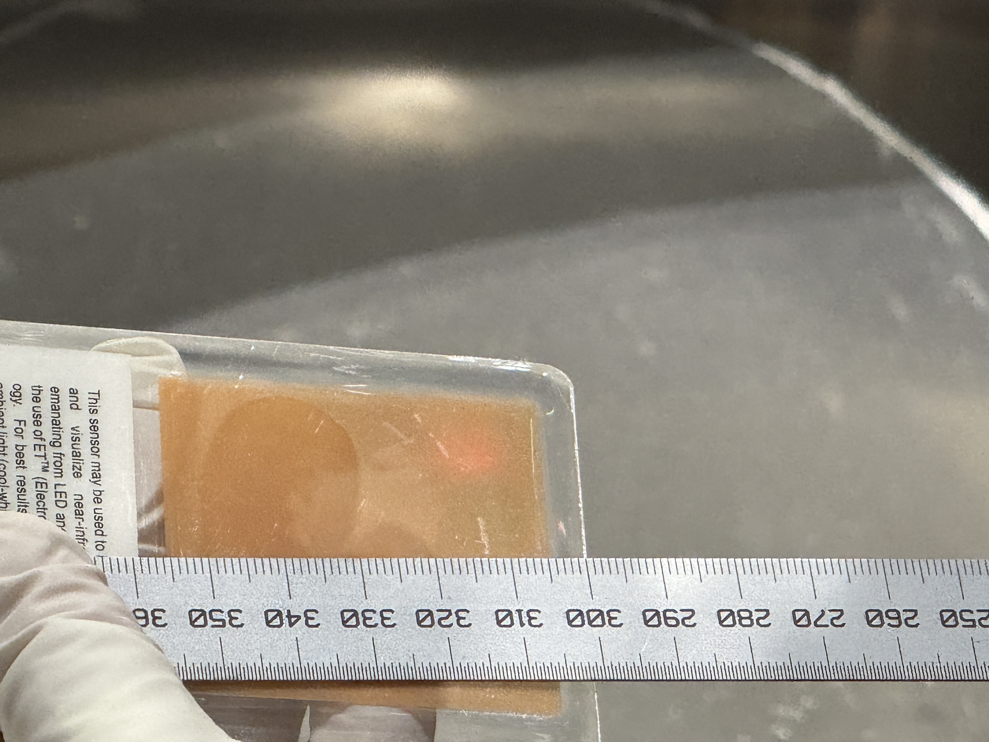
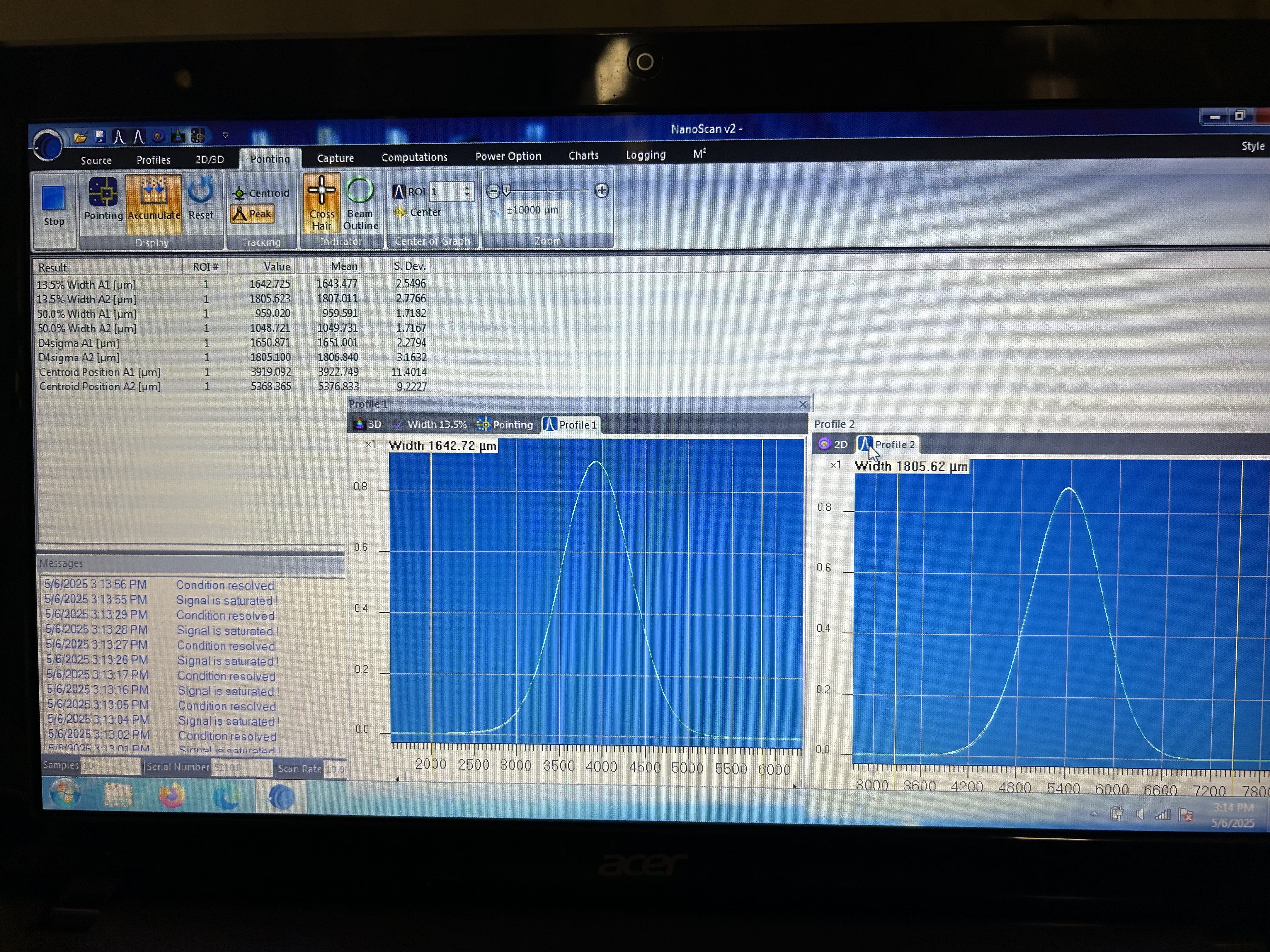
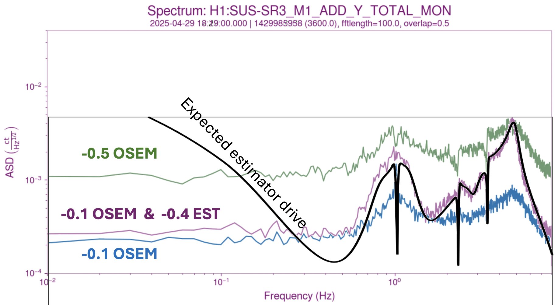
The third attachment shows the intended drives from the estimator and OSEM-only paths. They look similar enough that we believe the miscalibration issue has been resolved. For now we stand by until there is a chance to test the scheme again.
