patrick.thomas@LIGO.ORG - posted 13:31, Thursday 19 November 2015 (23569)
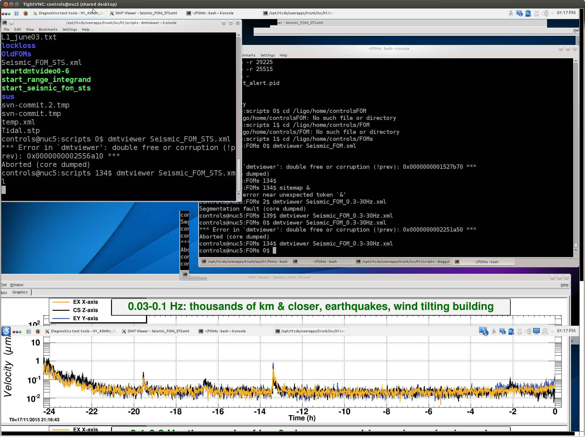
Seismic DMT viewer crashed
I restarted it. Screenshot of error attached.
Images attached to this report
I restarted it. Screenshot of error attached.
Keita, Evan
We installed a mixer-based 45 MHz RFAM monitor using two spare 45 MHz spigots on the distribution amplifier on the ISC rack. This provides an unobtrusive way to look for 45 MHz amplitude glitches on the ISC rack (i.e., it does not require inserting anything into the main 45 MHz drive that goes to the EOM driver and the EOM). On the other hand, if the glitches are only on the main 45 MHz drive, this monitor will not tell us anything.
Set-up is as follows:
I have calibrated LSC-EXTRA_AI_1_OUT so that it is in volts. This channel is not dequeued, but if we have another hours-long episode of glitching we can watch the test points in real time.
Took me a while to figure out that "not dequeued" is really "not DQ-ed", which means that the channel is not in the permanent DAQ channel list (where it has the prefix _DQ).
Likely Keita and Evan disconnecting the RF AM monitor in the PSL enclosure.
Evan and Keita are disconnecting the RF AM monitor in the PSL enclosure.
Running a2l.
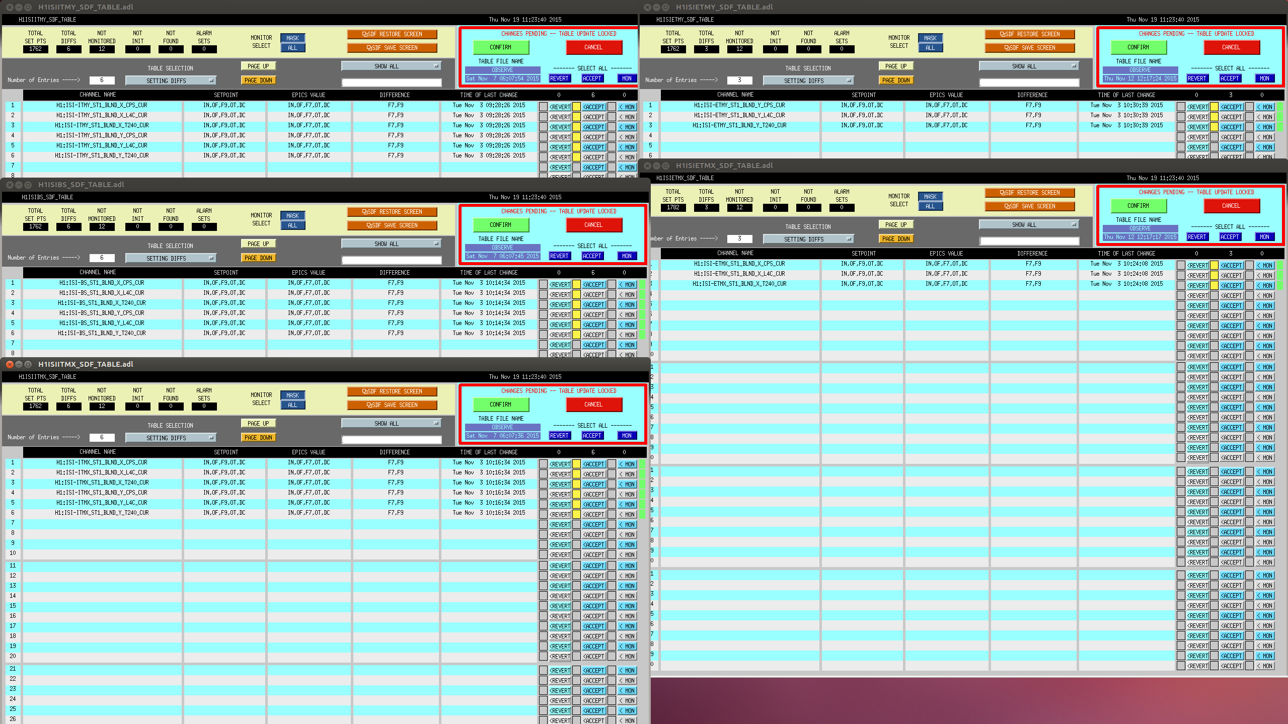
Accepted SDF differences for change of ISI blend filters.
The ISC_LOCK guardian was stuck at DC Readout Transition because the OMC wasn't ready, although the guardian log only said "not ready", and there was no notification that popped up. Patrick re-requested the OMC guardian to go to Ready For Handoff (which worked), but I also added a notify to the ISC_LOCK guardian to say "OMC not ready" if this happens again.
Lost lock trying to engage ISS second loop by hand.
SUS SR2 saturating 17:48:35 UTC
Keita says that the powering down of the RF AM monitor broke the lock.
Did this yesterday afternoon (11/18) but forgot to log it then.
17:10 UTC Out of observing for Keita to test grounding configurations for RF AM monitor. Not going into PSL enclosure. (WP 5616)
TITLE: Nov 19 Owl Shift 08:00-16:00UTC (00:00-08:00 PST), all times posted in UTC
STATE Of H1: Observing at 80 Mpc
SUPPORT: David, Laura, TJ, Andy, Dan (sorry if I missed any of you!)
LOCK DURATION: 7 hrs 53 mins
INCOMING OPERATOR: Patrick
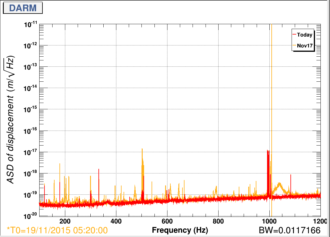
END-OF-SHIFT SUMMARY: We have nasty stationary lines between ~100-1000Hz since we started locking 12 hours ago. Few Detcharians gathered this morning to follow this up. Keita arrived and shed the light to this mystery that it is in fact the newly installed RF monitor injecting noise into DARM (alog 23555).
ACTIVITY LOG:
15:16 Bubba driving along the arms to check on tumbleweed
15:29 Bubba back. The landscape crew is taking care of it. They're working from 250m from EX towards Corner station.
TITLE: 11/19 [DAY Shift]: 16:00-24:00 UTC (08:00-16:00 PDT), all times posted in UTC
STATE Of H1: Observing @ ~ 80 MPc.
OUTGOING OPERATOR: Nutsinee
QUICK SUMMARY: From the cameras the lights are off in the LVEA, PSL enclosure, end X, end Y and mid X. I can not tell if they are off at mid Y.
Earthquake seismic band is between ~ 0.01 and 0.03 um/s. Microseism has been coming down and is between 0.1 and 0.4 um/s.
Winds are between ~ 0 and 5 mph.
ITMX, ITMY and BS ISI blends are on 45mHz. EMTX X and ETMY Y ISI blends are on 45mHz. ETMX Y and ETMY X ISI blends are on Quite_90.
I've been noticing all night but not sure where from. Those nasty little lines seem to have come with a broad peak at 1040Hz. It's not the violin mode second harmonics (which ends at ~1010Hz).
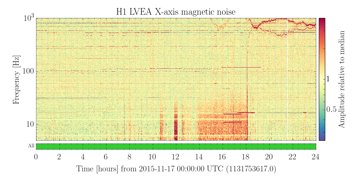
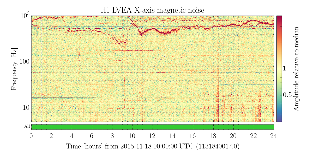
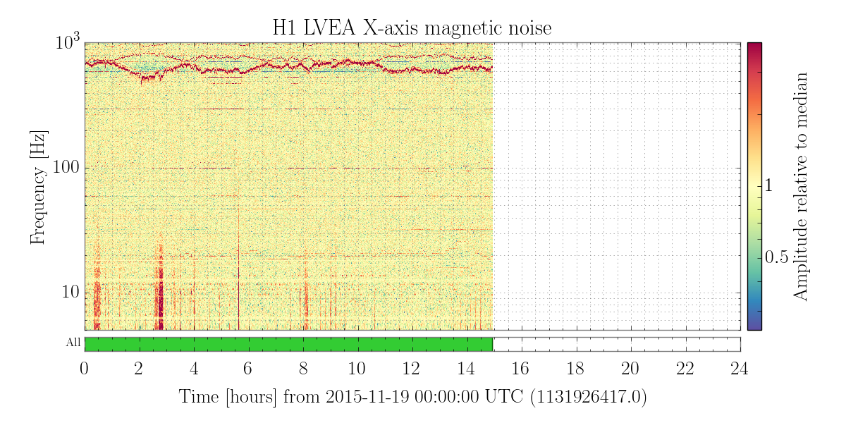
A quick look at the summary page tells me that LVEA magnetometer noise started to get bad towards the end of November 17. No one seems to noticed it since we hadn't locked until last night. I've attached the spectrogram from the summary page from Nov17, 18 and 19 below.
When mysterious lines appear I'd like to think of beckhoff issue but I don't have a way to prove it. Worth checking maybe?
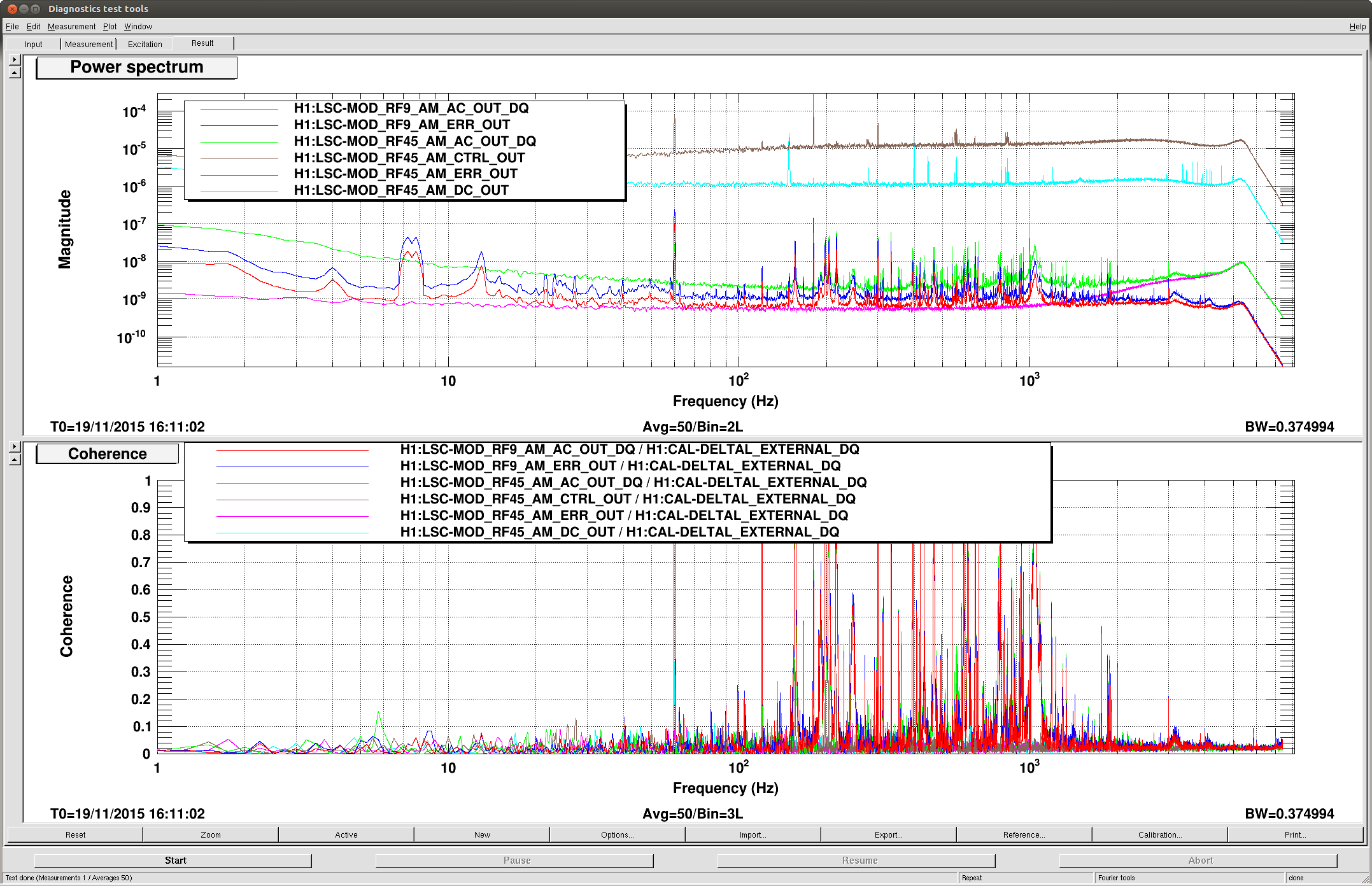
It seems to be related to newly installed RF AM monitor unit. RF AM monitors are "quiet" in that it's not glitching but the coherence is clearly there.
RF45 in-loop sensor (RF45_AM_ERR and CTRL) doesn't seem to see anything, but the out-of-loop sensor (RF45_AM_AC) and RF AM monitor both ways (RF9_AM_AC and ERR) are highly coherent with DARM.
Found damp settings for 1009.0273 Hz and 1009.6825 Hz (ETMY). Both lines have very low amplitudes to begin with (only a magnitude above the noise floor) so once I was able to damp them slightly I turned the damping off. Here's the table. The BP filters live in ETMY L2 DAMP MODE4 FM7 and FM10.
