Yet again, we had trouble with engaging the ISS.
I put in a notification during ENGAGE_ASC_PART3 for the operator to check the diffracted power level if it is more than 0.8% away from nominal. While it's probably okay if it's within 1% (other alogs say 2%, but I've had more consistent success with 1%), I chose a somewhat smaller number out of an abundance of caution.
However, even though the diffracted power was within a few tenths of a percent of nominal, the ISS would stall, and not engage.
As part of the PREPARE_ISS state, the guardian changes some setpoint values such that the H1:PSL-ISS_SECONDLOOP_SIGNAL_OUTPUT channel becomes small. We need to do this so that the DC-coupled ISS doesn't kick us out of lock when it is engaged. (For unknown reasons, this convergence has seemed to be more successful when the diffracted power is close to 8%). This SECONDLOOP_SIGNAL_OUTPUT wasn't converging though. It was bouncing around between +/-5 counts. The absolute value of this channel must stay below 2.5 counts in order for the ISS to close the second loop.
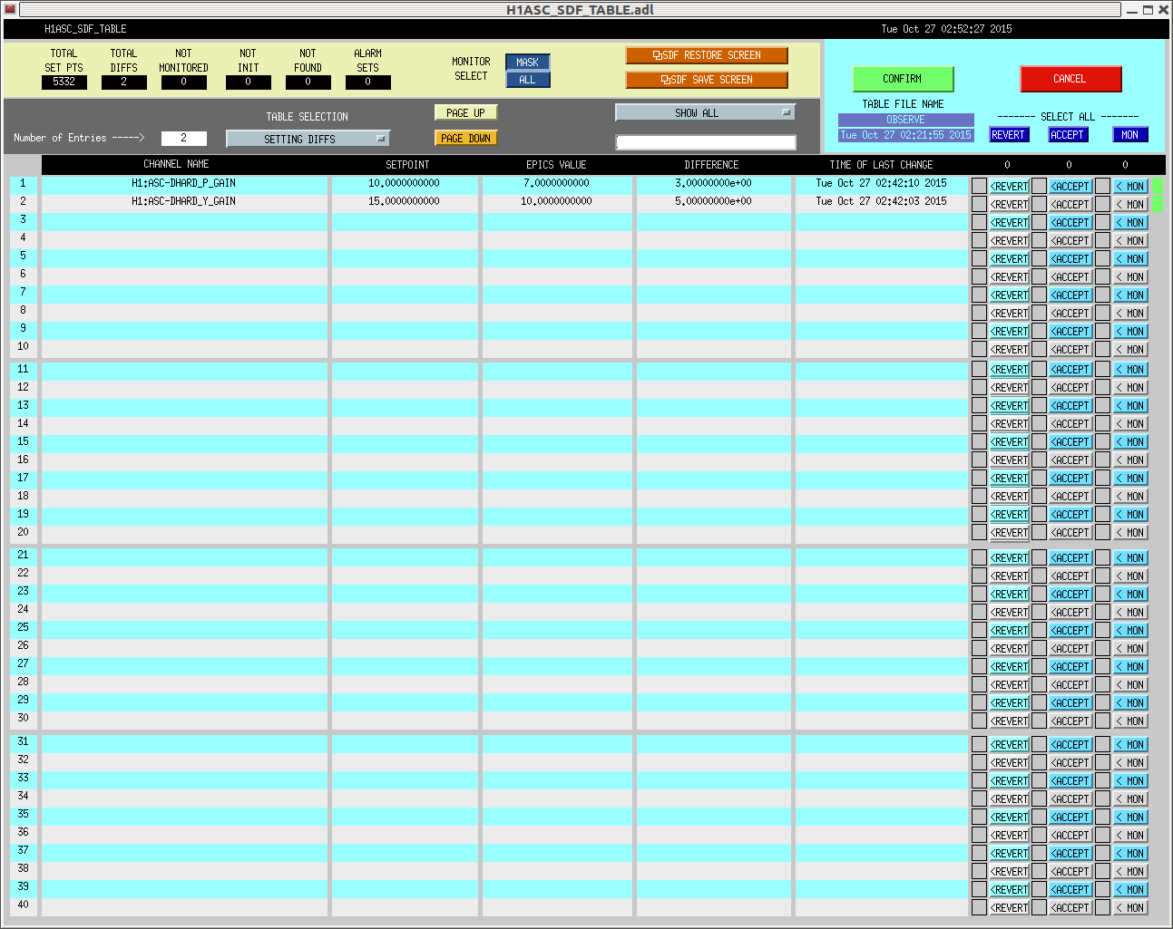
In the end, what I did, was cheat and change the gain H1:PSL-ISS_SECONDLOOP_SIGNAL_GAIN to 0.1 so that the ISS second loop would turn on. Then, VERY slowly I turned the gain back after we had arrived at NomLowNoise. As I increased the gain in steps of 0.1, the diffracted power dropped by half a percent or so. So, at each step, I waited for the diffracted power to come back near 7% or so before going to the next step. While this worked once, it has failed a few times after that, so let's not make it the new plan.
Patrick and I called Kiwamu, and followed the instructions in aLog 22449 to manually turn on the second loop (basically, turn on the button next to "second loop input to first loop" on the second loop screen, when the second loop output (near bottom right of that screen) is close to zero). Anyhow, that is making the diffracted power go super low (less than 1% sometimes), until the outer loop loses lock, and the diffracted power jumps up really high (45% or more). At this point, it's not at all clear why this isn't working, so Kiwamu is on his way in to try to diagnose things.
We've checked in with Mike, and since LLO is still down, if Kiwamu and Ed can't figure out the ISS, we'll call off the rest of the owl shift.