TITLE: Nov 6 DAY Shift 16:00-00:00UTC (08:00-04:00 PDT), all times posted in UTC
STATE Of H1: Observing
SUPPORT: Keita, Cheryl, Vern, Richard
LOCK DURATION: ≈2 hrs (this shift)
INCOMING OPERATOR: Jeff B
END-OF-SHIFT SUMMARY: IFO Locked and Observing 78Mpc.
Handing off to Jeff B.
ACTIVITY LOG:
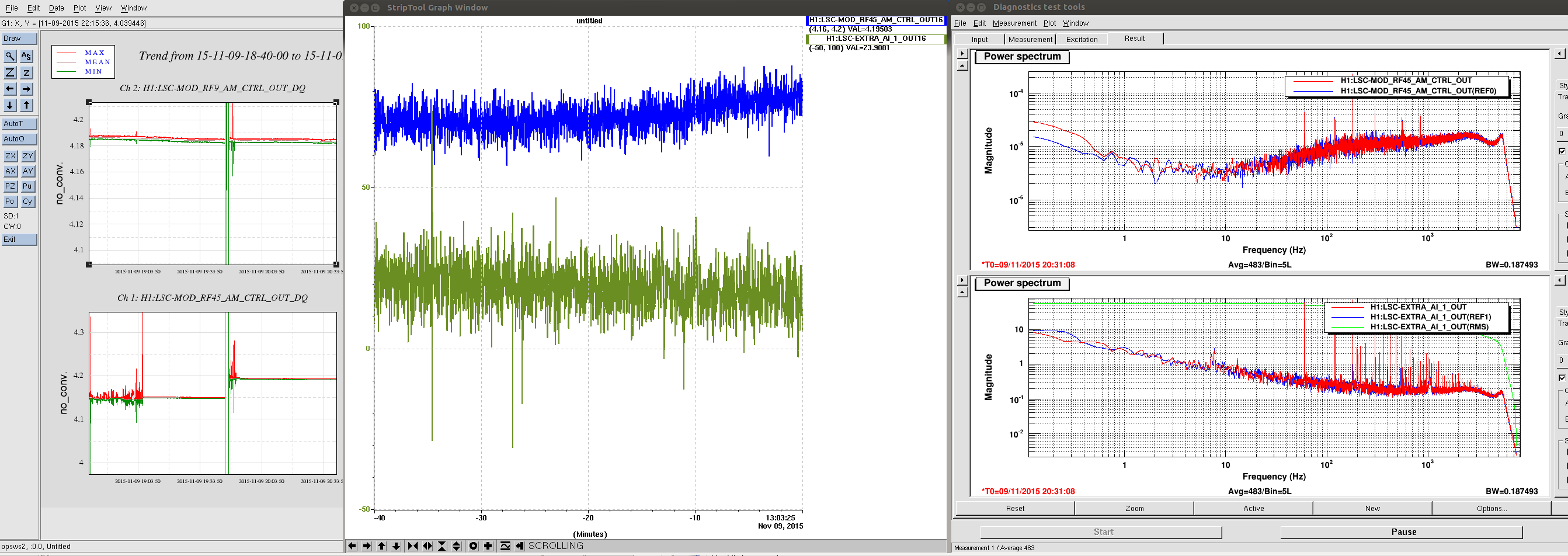
16:00 Peter and Richard going into H1 PSL to troubleshoot RF45 problem
16:05 45MHz issue seems to have corrected itself upon my arrival. I adjusted the RF out gain back to original value as noted in Nutsinee’s aLog(LSC-MOD_RF45_AM_RFSET) aLog #23222
16:06 6.2Mag quake in Aleutians has eq bands up to 10µm/s. Terramon lagged this information ≈33 minutes.
16:15 Joe and Chris headed down X-Arm for beam tube work
17:31 Kyle headed out to X-2-8 to drop off some hardware and then returning.
17:48 Bubba back from EY but heading back for a quick round trip.
18:00 Kyle back
19:19 Keita and Vern will be going into LVEA to further investigate 45Mhz trouble.
20:07 Joe and Chris back from X-arm for lunch
21:12 Keita tell me that I can have the IFO in about 5 minutes!
21:16 Joe and Chris going back out to X-Arm
21:35 begin intial alignment
21:50 Kyle headed back to x-2-8
22:39 IFO locked at NLN
22:48 Robert into LVEA to do injections (≈20min) Then we will proceed to Science Mode
23:34 Joe and Chris back from working on x-arm


