TITLE: Nov 6 DAY Shift 16:00-00:00UTC (08:00-04:00 PDT), all times posted in UTC
STATE Of H1: Observing
SUPPORT: Kiwamu
LOCK DURATION: ≈2.5 hrs (this shift)
INCOMING OPERATOR: Nutsinee
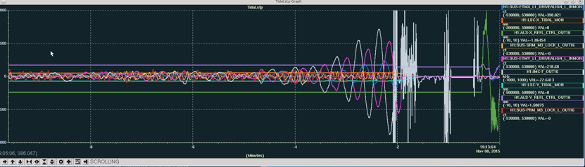
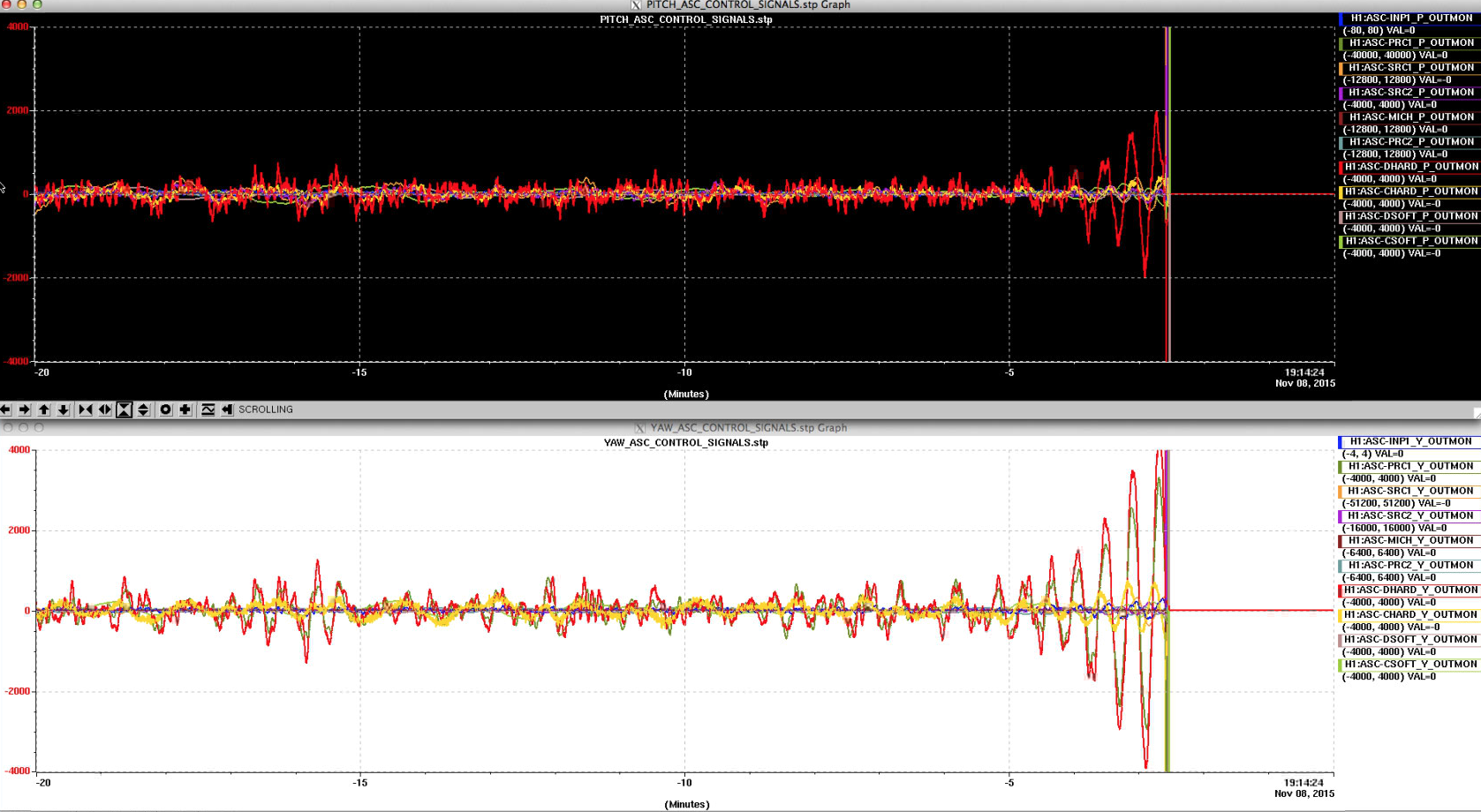
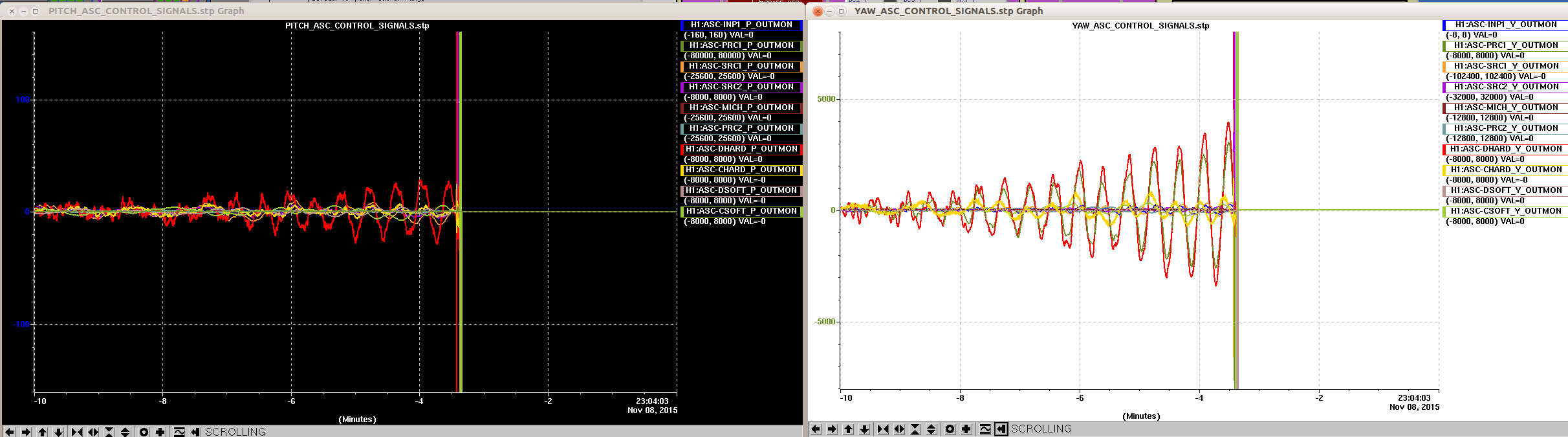
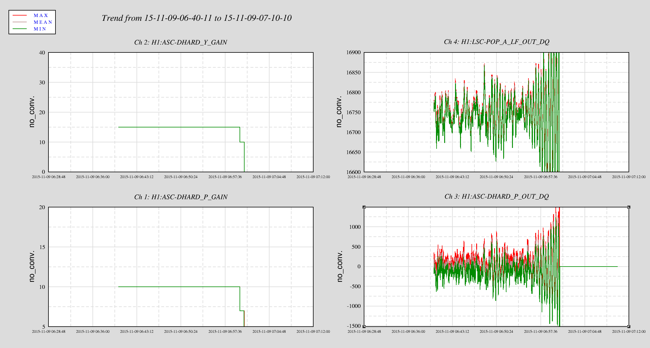
END-OF-SHIFT SUMMARY: IFO Locked and very glitchy(too many ETMY saturations to list). High amounts of earthquake activity had us down since Patrick turned over to me. Then another barrage of quakes ensued. µSeism is between .7-1+microns. High ground motion is obvious in POPAIR_LF_90, ASC Yaw signals and in Tidal StripTool Wind is picking up this afternoon exceeding 20mph only for a short while. Handing Nutsinee a locked Interferometer.
ACTIVITY LOG:
16:20 Robert out to LVEA to install a shaker.
17:30 Spent some time on the phone with Kiwamu getting this M2 to M1 SR3 offloading issue handled. Then another 3.9µcron from a 6.4mag in Indonesia. It’s going to be a bumpy day.
19:21 Looks like a good time to try and make something happen. EQ bands are back down in the .1µ region
20:15 after much struggling with alignment, Kiwamu is on site and showed me how close I was and how to overcome my impasse. Alignment commences. EQ bands now below .1µ. Sudarshan is also on site.
21:42 Intent Bit to Undisturbed