Keita, Evan
We went into the PSL to see if we could find a source for today's 45 MHz glitches.
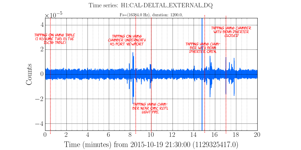
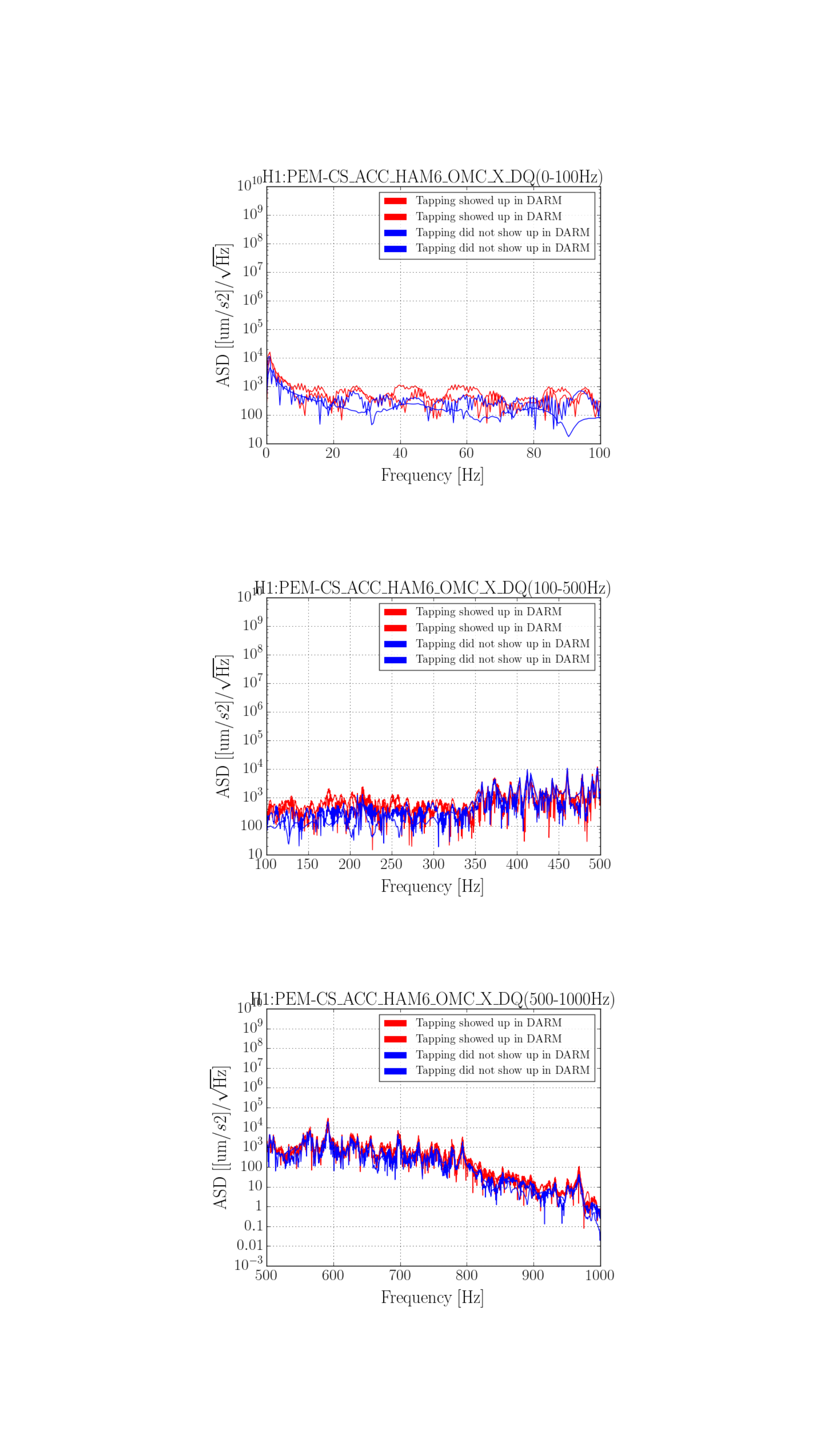
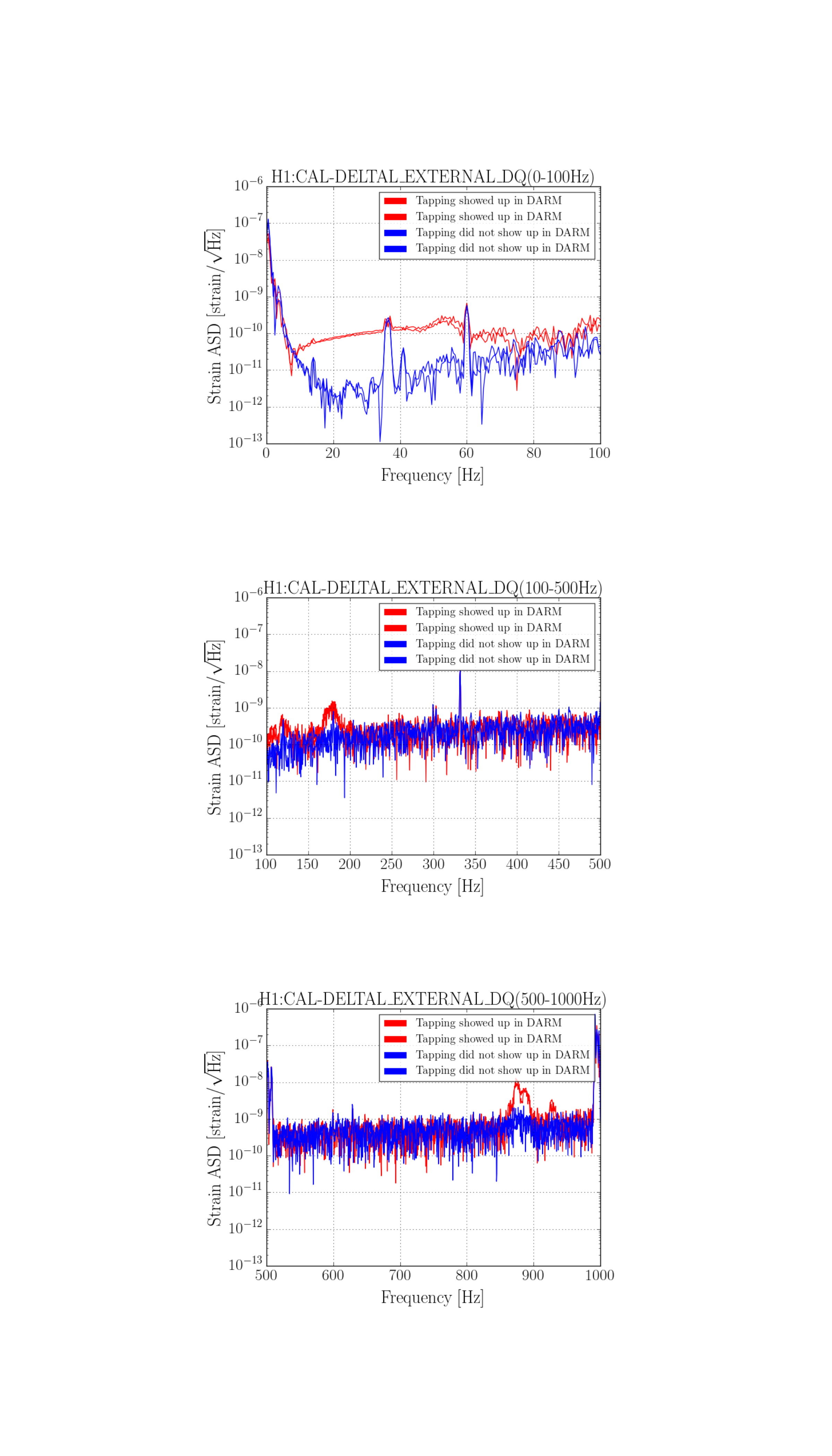
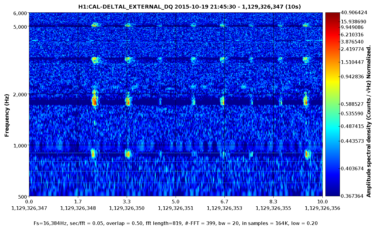
We didn't find anything conclusive. Mostly, it seems that bending the main cable (the LMR195 that carries the 45 MHz into the PSL) causes large glitches in the AM stabilization control signal, similar to what is seen by bending/tapping the LMR195 cable at ISC R1. We did not really see anything by bending the slow controls / power cables, or the rf cable that drives the EOM.
The main cable passes from the ISC rack, through the PSL wall, through the (overstuffed) cable protector on the HPO side of the PSL table, over the water pipes underneath the PSL, and then terminates at the EOM driver, which sits just underneath the PMC side of the table. Keita notes that the pipes don't seem to be vibrating.
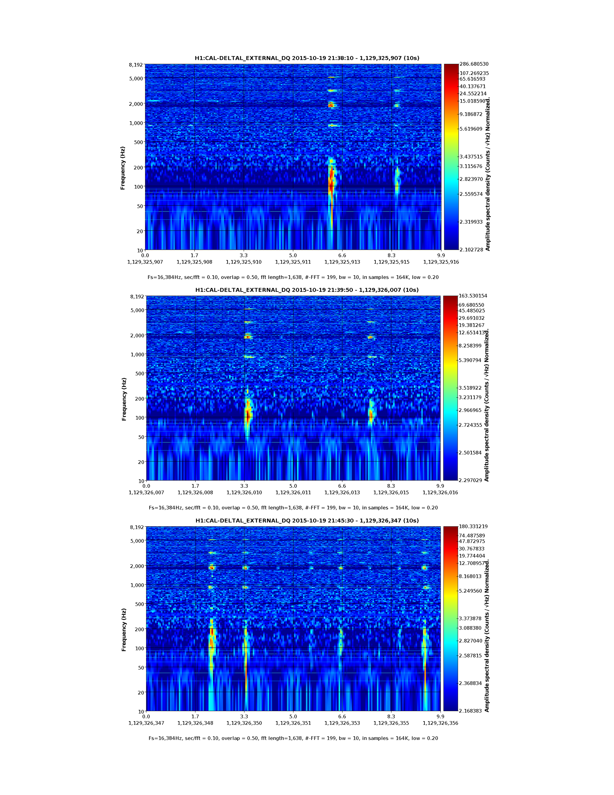
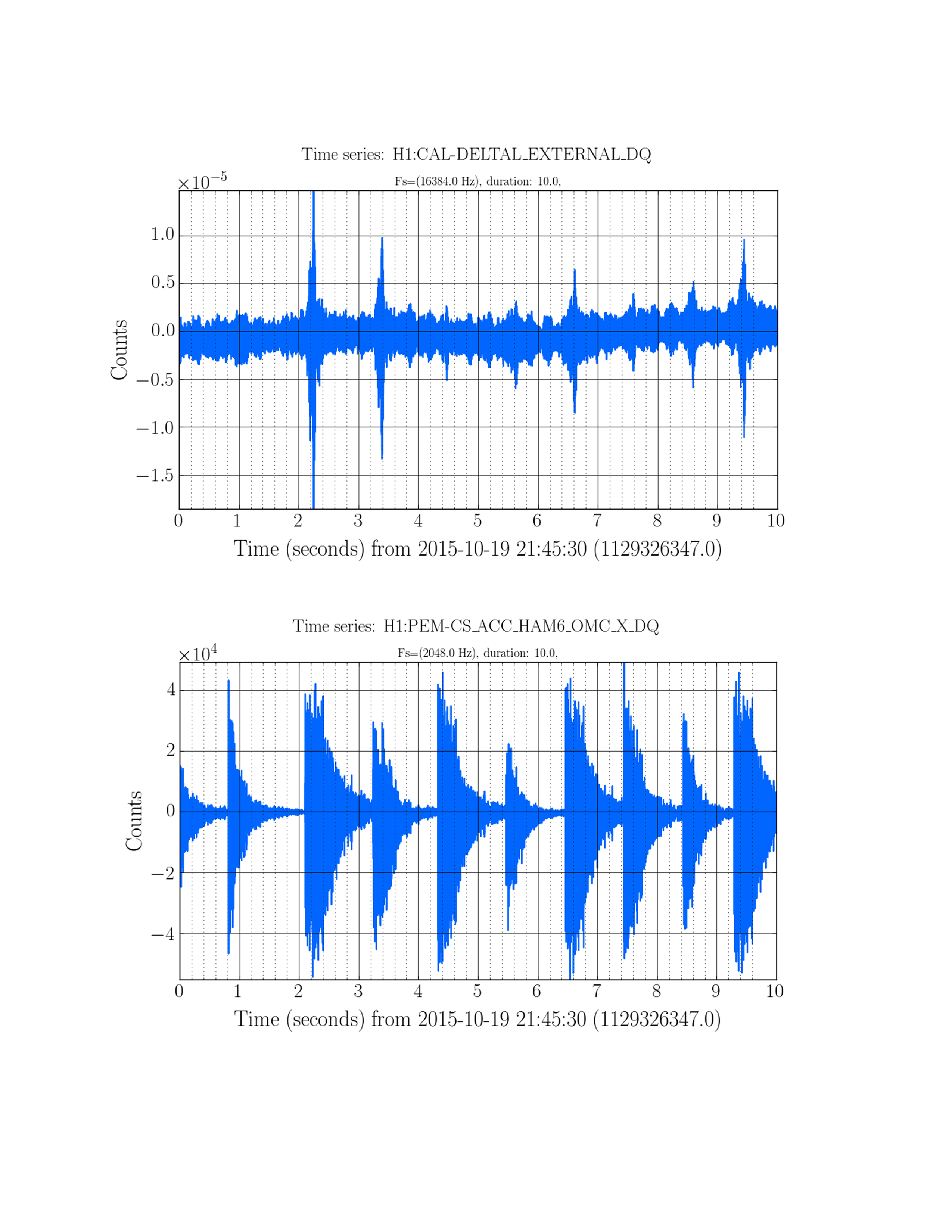
It is worth noting that these glitches, which are clearly seen in the control signal time series of the EOM driver in the PSL, do not show up in the control signal time series of the spare driver hooked up in the CER.
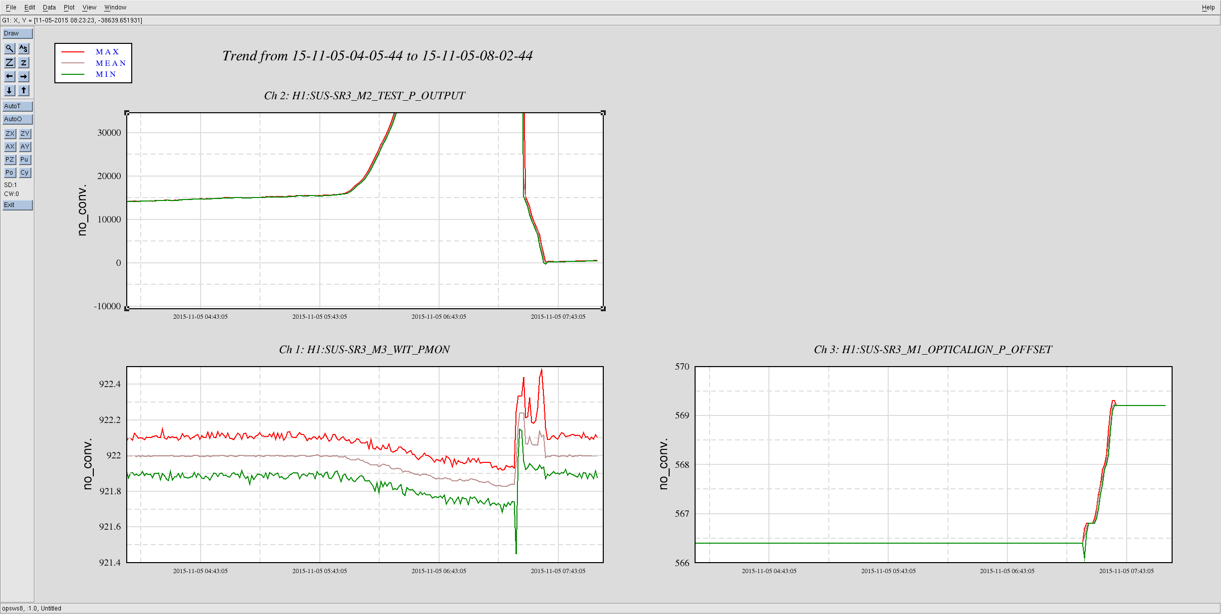

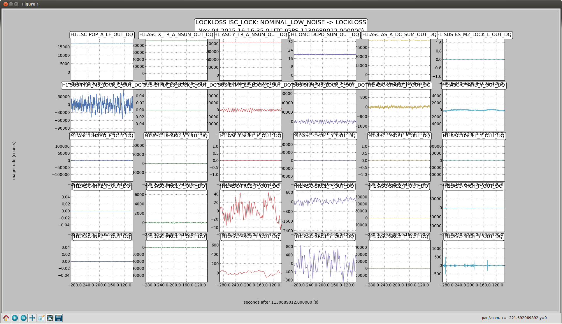
Not sure what the cause of the power drift / alignment drift was, but it looks like we may have lost lock when the power recycling gain dropped below 33.5-ish. See aLog 23164 for some plots and details.