nutsinee.kijbunchoo@LIGO.ORG - posted 15:47, Tuesday 27 October 2015 (22896)
GRB Alert 22:40:40 UTC
DO NOT TOUCH THE IFO (for at least an hour).
DO NOT TOUCH THE IFO (for at least an hour).
Crusing at ~78 Mpc.
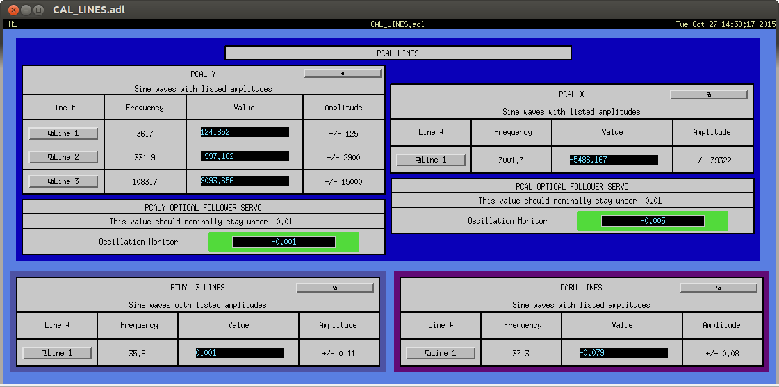
I made a new screen to help Operators check the status of the CAL lines. It shows the current value of the sine waves with their amplitudes and frequencies as well as the status of the Optical Follower Servos. The OFS Oscillation Monitor will have a green border if the absolute value stays under 0.01, and red otherwise. There are links to each of the line's medms for more information, if needed.
This is located under the CS CAL on the Sitemap.
LHO's fourth-Friday public tour occurred on the afternoon of 10/23. Arrival time at LSB = 2:30 - 3:00 PM. Departure time = 5:00 PM. Group size = ~12 adults. Vehicles at the LSB = ~6 passenger cars. The group was on the overpass near 4:15 PM and in the control room from about 4:30 to 4:50.
J. Kissel, N. Kijbunchoo, S. Dwyer

After a pretty breezy maintanence day, we've successfully achieved nominal low-noise in record time.

Good job team!

P.S. We're going to run a few commissioning measurements before heading into observation mode. Expect science in about a half hour.
Sudarshan, Kiwamu, (WP#5569)
During the maintenance period in this morning, we looked at a few things in order to improve the ISS robustness.
In summary, the 2nd loop ISS is not back in a great shape yet. There will be some times where it needs the manual engagement.
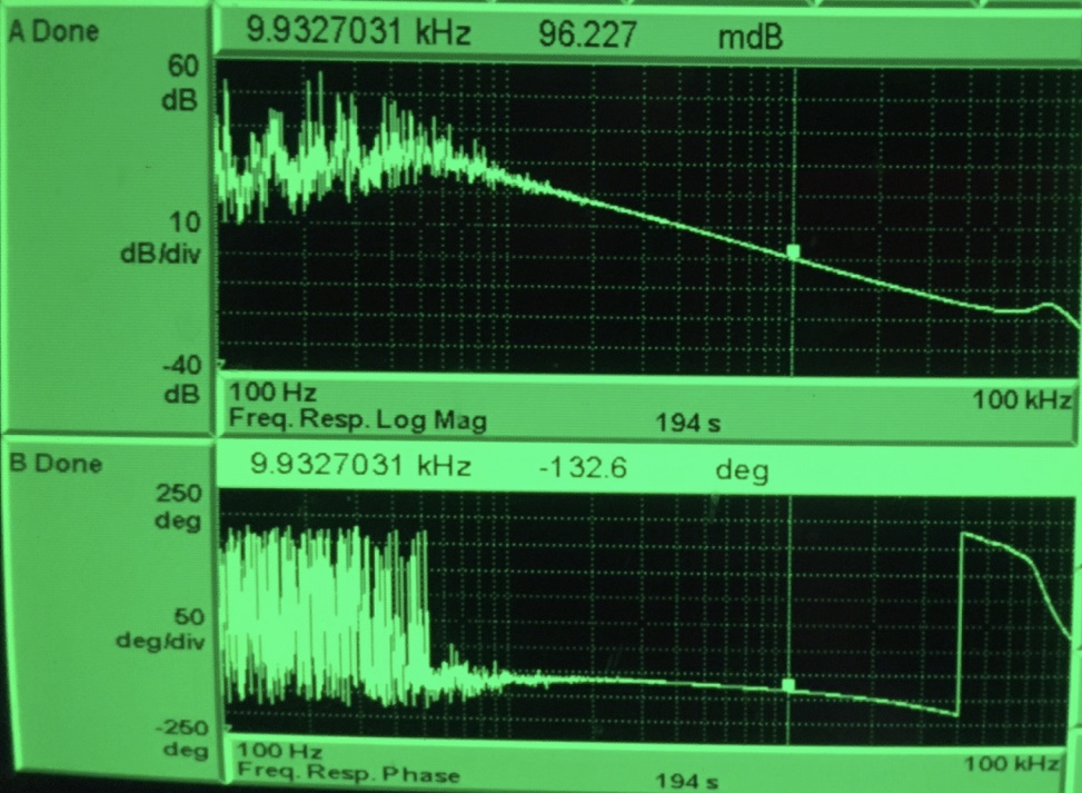
(1) The open loop measurement suggested that the UGF is at 10 kHz with a phase margin of about 50 deg. No crazy thing was found.
(2) The PID loop seems to have been suffering by unidentified extra offset, which explains the behavior we saw yesterday (alog 22863). I have edited the IMC_LOCK guardian so that it servos to a better locking point where the transient is less in the diffraction power.
(3) The IMC seems to be adding extra intensity noise below 1 Hz. This is the main reason why the PID loop does not converge simply because it is too high.
Change in the PID locking point
After a number of the 2nd loop engagement tests, I confirmed that it was the PID loop which pulled the diffraction power to a small value (alog 22870). This happens even without any additional gain or boosts which are engaged in the CLOSE_ISS loop. The reason of this bad behavior was found to be due to a different (unidentified) offset in the SECONDLOOP_SINGAL. I do not know why it changed. Originally the guardian was supposed to servo SECONDLOOP_SIGNAL to 0.7 which had been fine in the past in terms of transient kick to the first loop. However, as reported in the recent alogs, this locking point became bad in the sense that it gave a too large kick and eventually unlocked both 1st and 2nd loops. I experimentally adjusted the offset point which ended up with -0.4. I have edited the guardian accordingly and checked in to the SVN.
I then tested the manual engagement with the new PID locking point multiple times (Note, I did it manually because the PID loop was not able to converge due to large motion in the IMC). I confirmed that it did not pull the diffraction to a small value. Though it often lifts up the diffraction up to about 10% which is acceptable.
Extra intensity noise from IMC
This is something we already knew (alog 22482), but intensity noise became higher at low frequencies as the light goes through the IMC. This is likely due to some static misalignment somewhere (or perhaps very large offset in the length control) in the IMC. In order to identify which optics are contributing most, I looked at several channels for SUS-MC1, MC2 and MC3, and HAMs 2&3 table motion. However, sadly, all three MC optics and both HAM tables seem to equally contribute to the intensity fluctuation seen in MC2_TRANS and ISS PD array below 1 Hz according to coherence. The contribution from yaw tend to be larger than that of pitch according to the coherence, but they all are above a coherence of 0.85 or so below 1 Hz. It is difficult to say what optics are contributing most.
We need to study why the IMC motion is so high these days.
For those who will engage the 2nd loop in the future
The manual engagement now works fine. As usual, when the 2nd loop does not engage on its own for more than 5 minutes or so, please follow the instruction for the manual engagement (alog 2249). Also, when the manual attemp fails (i.e. the deffraction power is pulled by more than 5 % when manually engaging), one can prevent a lockloss by manually disengaging the second loop input (the very top red button in the 2nd loop ISS screen). Subsequently one can make another attempt once the diffraction power settles.
Here is the TF measurement screen shot:
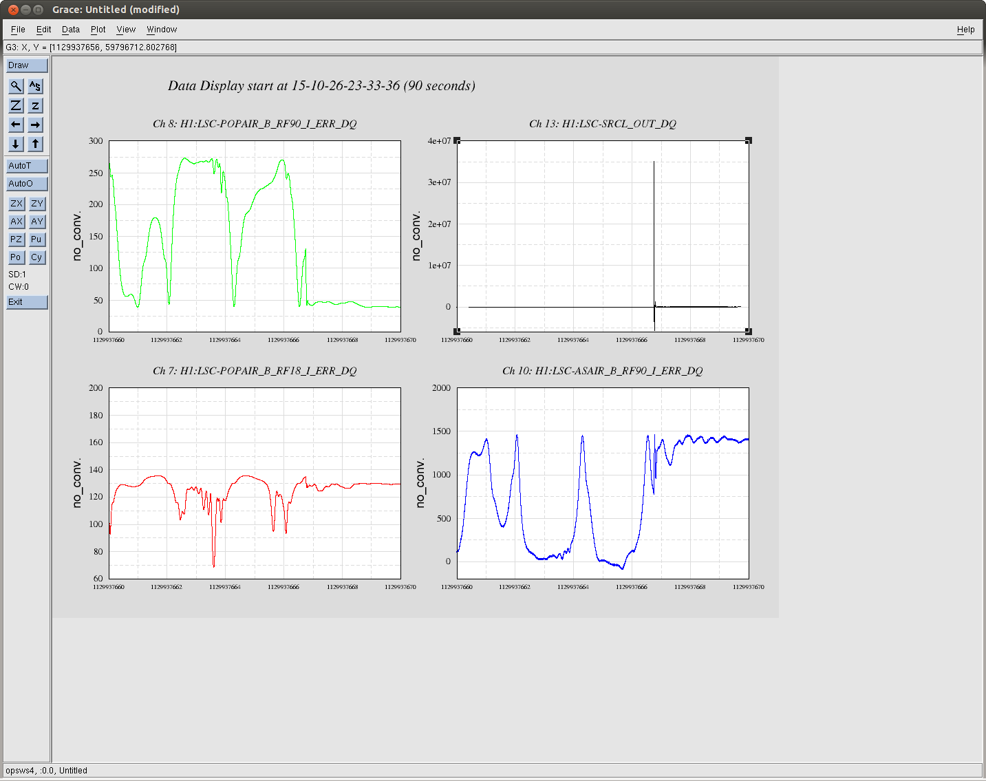
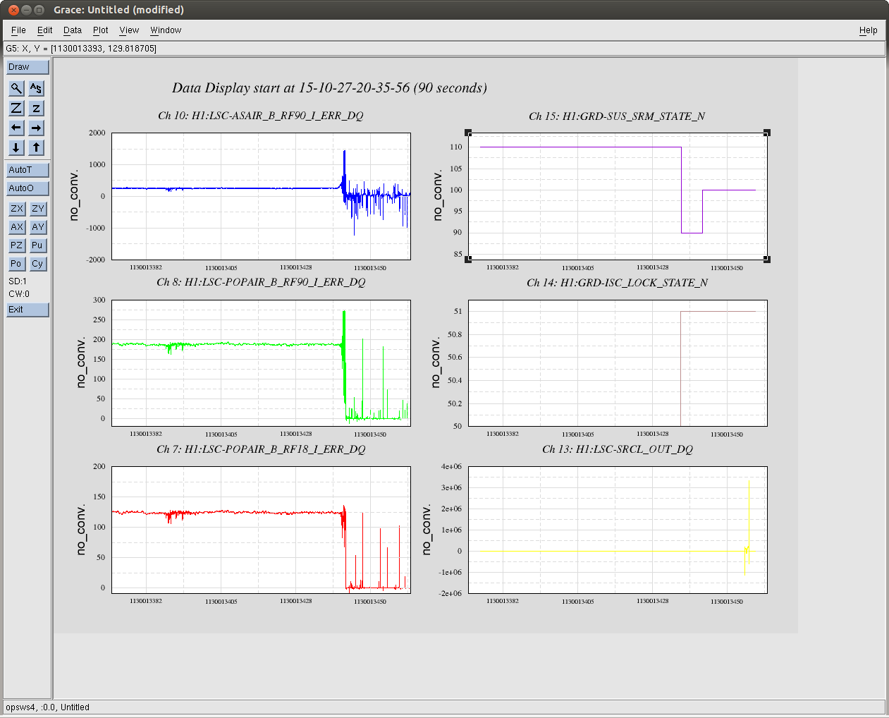
We implemented a version of the PRMI to DRMI transition that Stefan did by hand 20698 a few weeks ago (22472). It has worked a few times and not worked a few times, operators are using this only when the DRMI alignment is bad to improve alignment in PRMI. Here are plots of two examples of a sucessfull and unsucesfull transition. (failure at 20:37:19 UTC today, Oct 27, sucess at 10/26 23:35:05 UTC )
In the failure, the PRMI lock was lost when the SRM suspension started to realign SRM, before any feedback came on. Jeff and I changed the ramp time for SRM in the guardian to 10 seconds (I think the default is 2 seconds). We will see if this helps the PRMI lock to survive realigning the SRM.
Also, in the sucessfull attempt the SRCL feedback came on at a time that AS90 was high, and POP90 was low. It might be that triggering the SRCL output on one of these channels would be better than POP18.
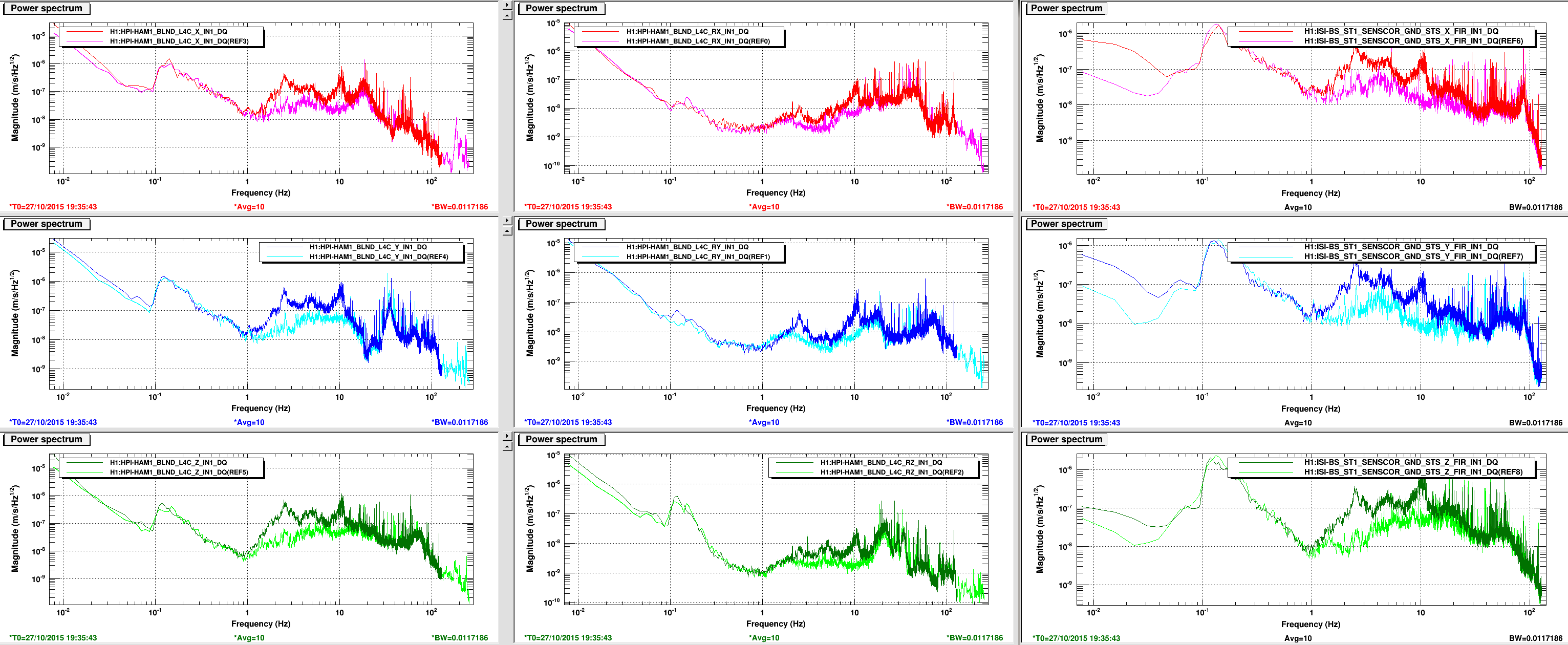
JeffK HughR
Attached are the Blend Input from the L4Cs and the Ground Seismos. Reference is from 4am today and the current is from about 1230pdt. The L4Cs are in the first 2 columns and the ground STS2s coming into the Sensor correction path are in the last column. The increase in motion seen is a direct reflection of increased daytime ground motion. Does not look like there is any increase in motion not attributed to the ground motion.
Temperature sensors for BSC9 and BSC10 were installed this morning. Sensors were installed on southeast corner of each chamber (next to SUS-R1 rack).

List of activities done at each end station:

EX
1. BNC cable from electronics room (PEM-C1) was pulled back from PEM area in VEA and routed to Southeast corner of BSC9.
2. Power cable was pulled from SUS-R1 to BSC9.
3. Temperature sensor was installed by using a C-clamp to hold sensor securely next to chamber outer wall.

EY.
1. BNC cable was pulled from electonics room (PEM-C1) to southwest corner of BSC10.
2. Power cable was pulled from SUS-R1 to BSC10.
3. Temperature sensor was placed in final location, but not secured by C-Clamp.
BrianL, JimW
Brian and I are investigating the HAM3 .6hz, looking at the tfs we took post chamber closeout in 2014. Brian wanted to look for the possibility of some magnetic coupling from the actuators to the sensors, so we were looking more closely at the cross terms in the transfer functions. We looked at a lot of the cross couplings, but most of them were uninteresting. We thought we found something on the V3 actuator on HAM3 (first pdf) at about .65 hz, but when we looked at HAM2 (second pdf), the feature is even bigger, so we suspect that this is maybe due to the payload. It is suspicious that the vertical drive to horizontal coupling changes slope at about .6 hz, but not very conclusive.
I've also attached the script that we used to make the plots, but to run it you will have to correct the path to the data. The measurements we looked at were H1_ISI_HAM2_TF_L2L_Raw_2014_09_16.mat and H1_ISI_HAM3_TF_L2L_Raw_2014_09_10.mat in the HAM2 and HAM3 /Data/Transfer_Functions/Simulations/Undamped folders in the Sei SVN.
... and I just looked at the HAM3 summary page, and in case you were wondering why we are still looking at a problem that had fixed itself... it's baaaccckk...
Did not remove the existing pipe and the duct like pipe covers the lexan slot so that can not be used. Just loosened the hose clamp pulled the duct to completely cover the partly exposed slot and retightened the hose clamp--more than it was. Less likely to move now.
Kiwamu reported in 22781 about a couple lock losses due to the drive to HEPI hitting the 250um limit. HEPI can handle more than this but should not need to if the PSL (likely Ref Cav) temperature does not trend off somewhere.
Attached are several PSL Temp channels for 14 days with the limit hit time noted on the run away Tidal Channel. Certainly many of the PSL Temp channels show a trend that correlates pretty well with the run away. In iLIGO we had tight temp control of the Ref Cav, do we have a temp of the Ref Cav now or is there another signal that would best represent that?
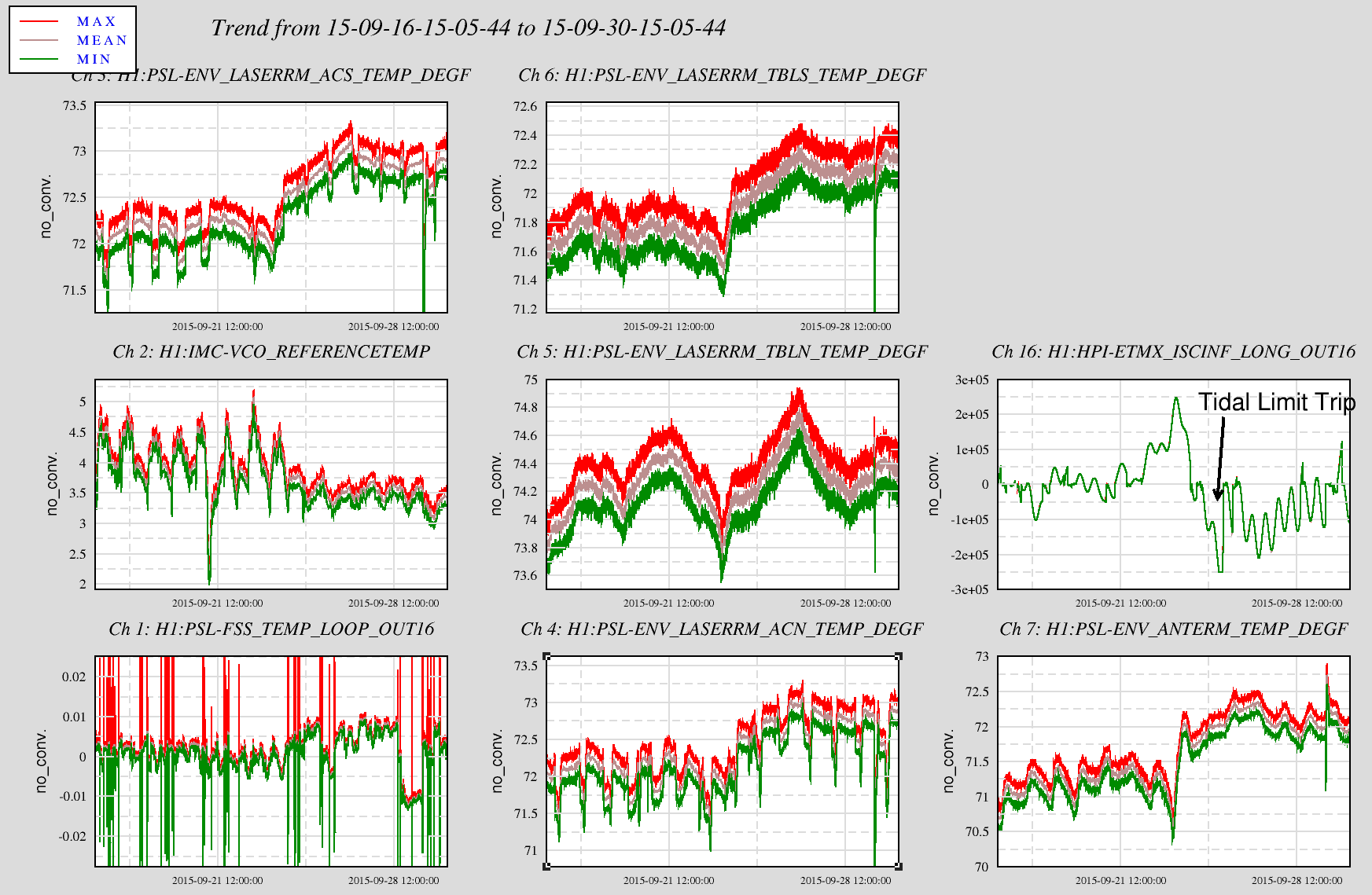
The Oct 11 near miss shows some trend as well but things are very suttle in this regard. We would be well served to tighten the ref cav temp.
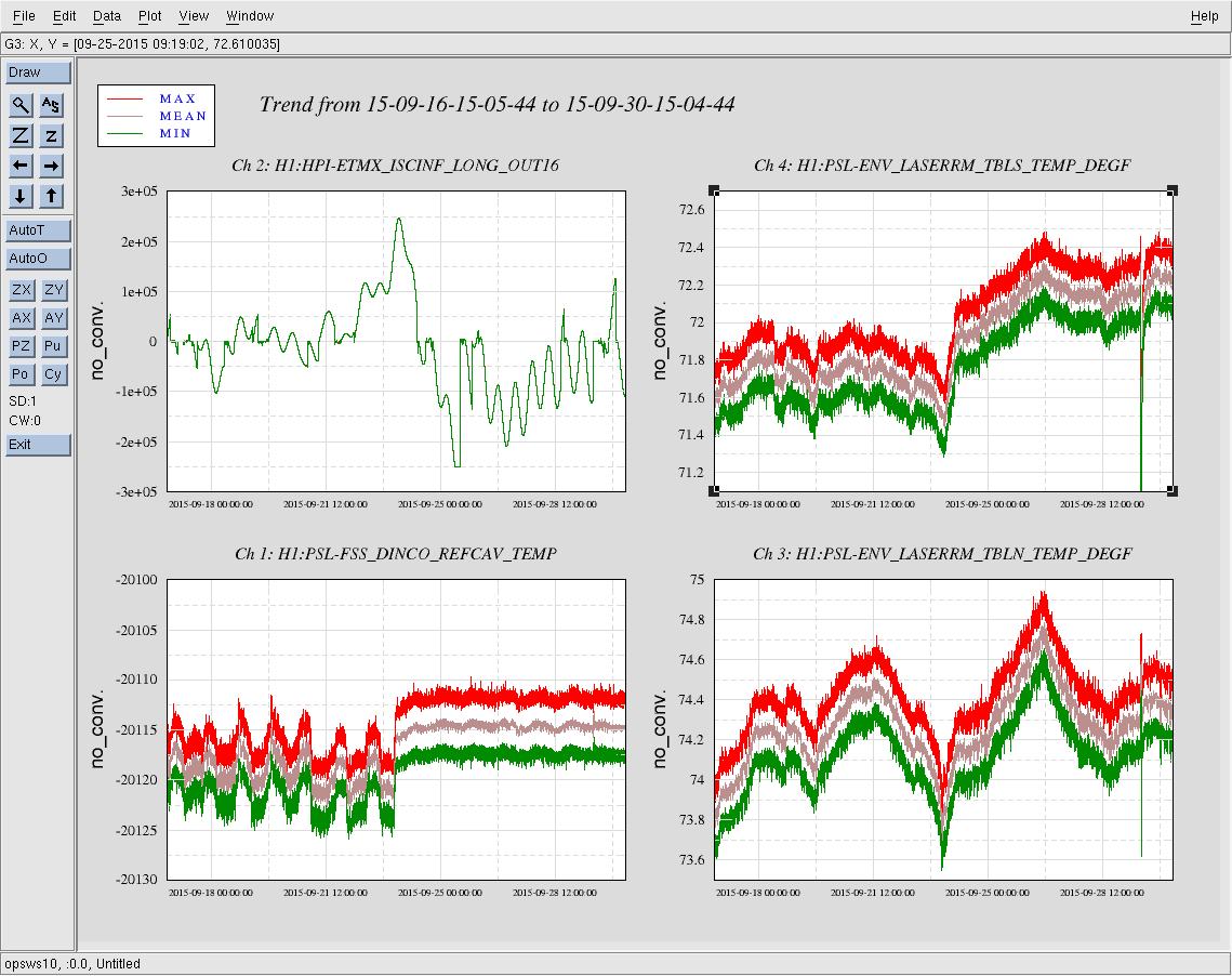
The signal for the RefCav temp is H1:PSL-FSS_DINCO_REFCAV_TEMP. Unfortunately this channel is not calibrated to degrees, it just reads out in counts. I've attached a trend over the same time scale as Hugh's above (14 days) of the ETMx HEPI tidal channel and PSL laser room temperatures, and also including the RefCav temp.
At ~13:45 on 9/23 (~48 hours before ETMx HEPI hits its tidal limit) the RefCav temp seems to respond to a temperature rise in the PSL laser room; the temp in the laser room rose ~0.5 °F over the course of ~12 hours, leveling out at ~01:30 on 9/24. The RefCav shows a quick rise over the first ~45 minutes and then a slow rise and leveling off over the remaining 11 hours, also leveling out at ~01:30 on 9/24. And although the laser room temp continues to slowly increase over the next several days the RefCav temp remains steady.
A summary of the O1 stochastic hardware injection (spanning 1129673117-1129673717) recovery is available in the DCC:
https://dcc.ligo.org/G1501327
Josh, Laura, Andy, Duncan, TJ,
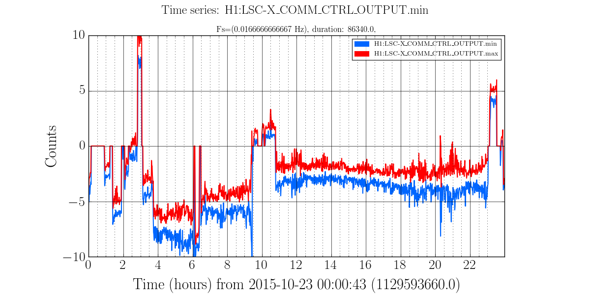
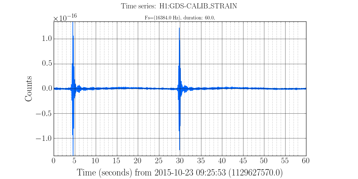
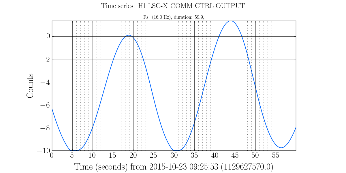
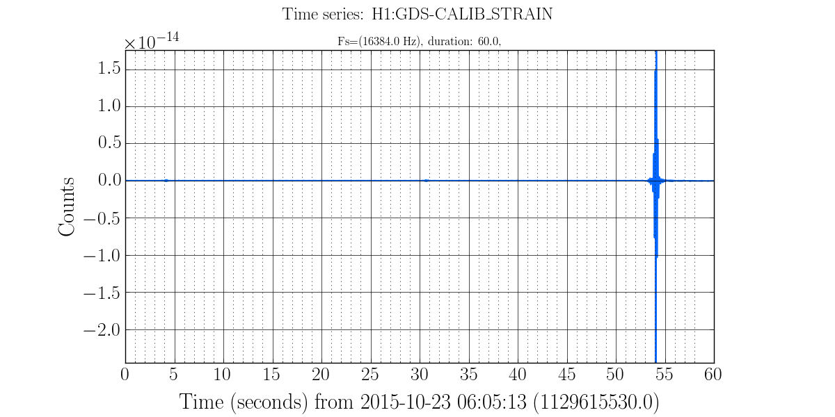
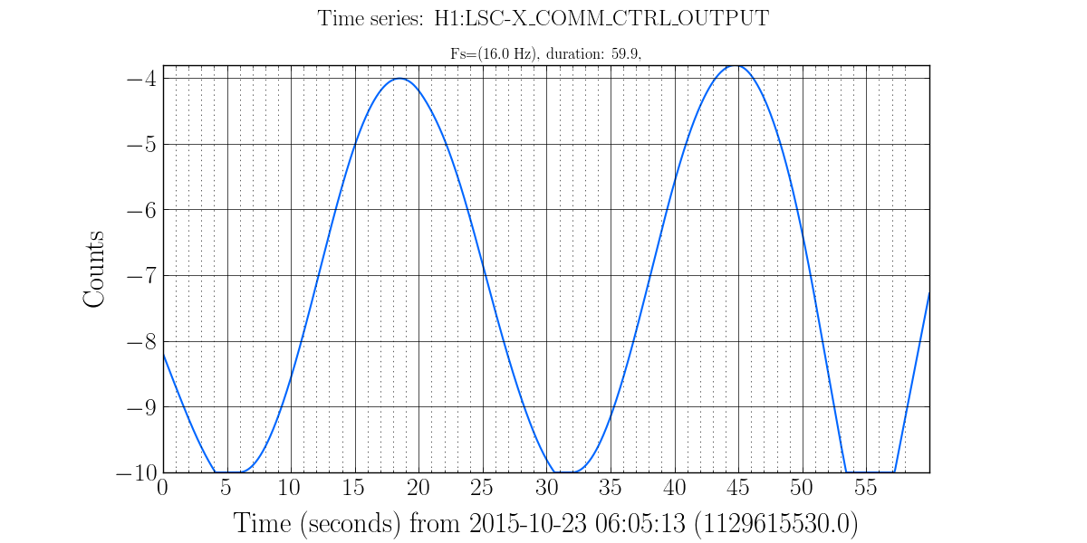
Laura noticed that on 10/23/15 LSC X COMM CTRL was hitting its software limit (10 um) while H1 was locked, according to the nice software limits page set up by Duncan M on the summary pages. We've previously seen common mode tidal control hit software limits back on (17654 and 18748 and I remember but can't find the commissioning work to improve this). The attached plots show 1) the times when the software limits were hit, both near to the end of lock, but in lock (likely leading to lockloss), 2) the 24-hour min/max plot for the control channel, 3-6) the control signal and GDS CALIB STRAIN for the two saturation times (four saturation segments, two at each time). It looks like sometimes lock is acquired with the common-mode control being already quite close to its limits. This happens rarely, this is the only day in the past week we have seen it.

I reset the H1 PSL power watchdog at 15:45 UTC (8:45 PDT).
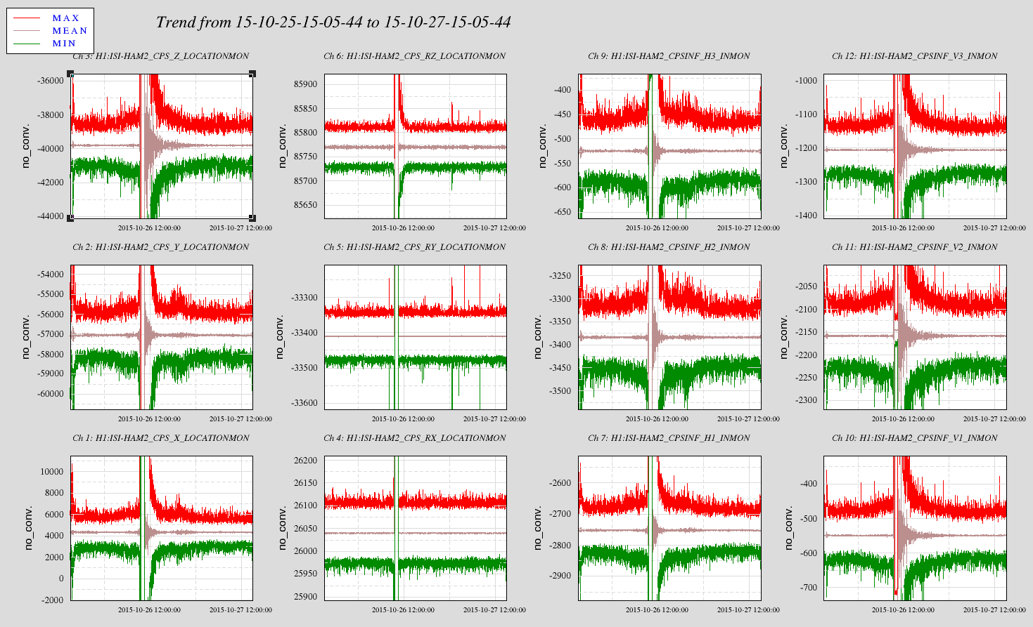
Attached are trends of the Cartesian and the Local Position Sensors from which they are derived. Unlike the HEPI after a trip, even the Local positions as well as the servo'd cartesian positions are bang on. The ISI platform is in the same place.
Richard has transitioned LVEA to laser safe. All doors are locked. PSL still up. IMC still locked.
Daniel, Sheila, Evan
Over the past 45 days, we had two instances where the common-mode length control on the end-station HEPIs hit the 250 µm software limiter. One of these events seems to have resulted in a lockloss.
The attached trends show the ISC drives to the HEPIs, the IMC-F control signal, and the IMC-F offloading to the suspension UIMs over the past 45 days. One can see two saturation events: one on 25 September, and another on 11 October.
We survived the event on 11 October: the EY HEPI hit the rail, and counts began to accumulate on the EY UIM, but the control signal turned around and HEPI came away from the rail. On the 25th of September, both end-station HEPIs hit the rail, and after about 2 hours of counts accumulating on the UIMs, IMC-F ran away (second attachment). Note that both HEPI drives started at 0 µm at the beginning of the lock stretch.
Both of these periods experienced large common drifts, when a pure tidal excitation would repeat after 24 hours. This may indicate a problem with the reference cavity temperature and PSL/LVEA temperature during these days.
Added PSL Temp Trends log in 22881.

