cheryl.vorvick@LIGO.ORG - posted 04:58, Thursday 15 October 2015 (22541)
GRB 11:54:11UTC
Called LLO and their GraceDB is now working, so they got the alarm.
Called LLO and their GraceDB is now working, so they got the alarm.
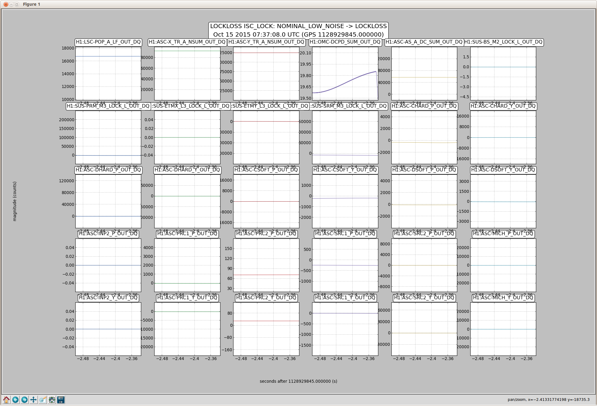
OMC-DCPD_SUM_OUT goes first
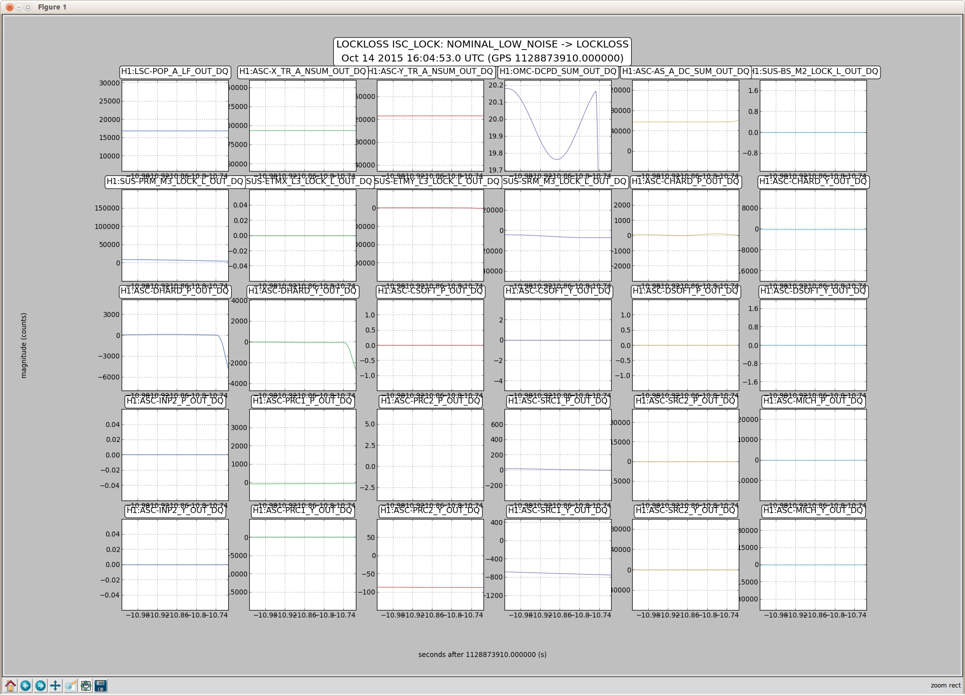
First plot shows the glitch, and the lock survives a short time.
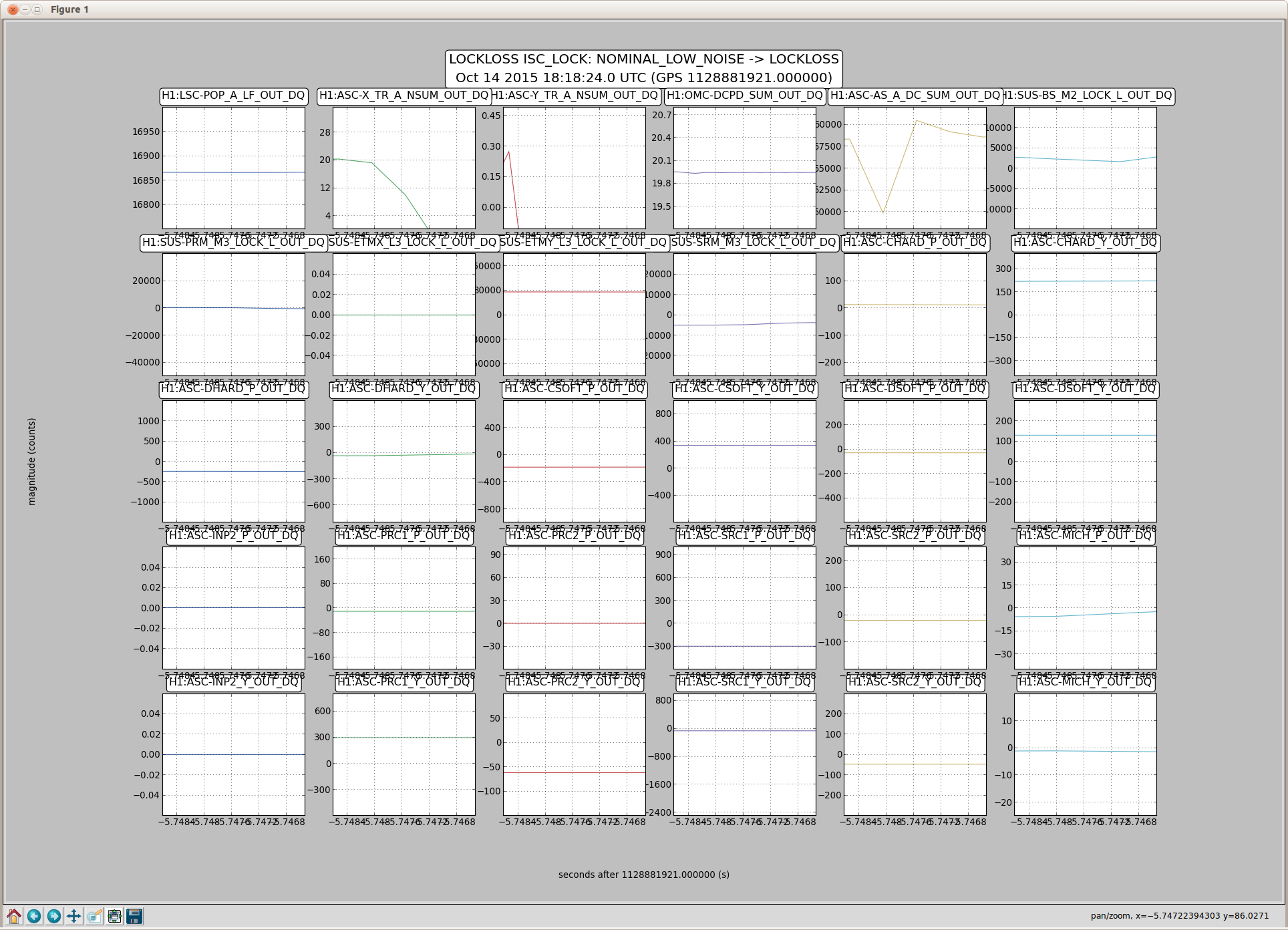
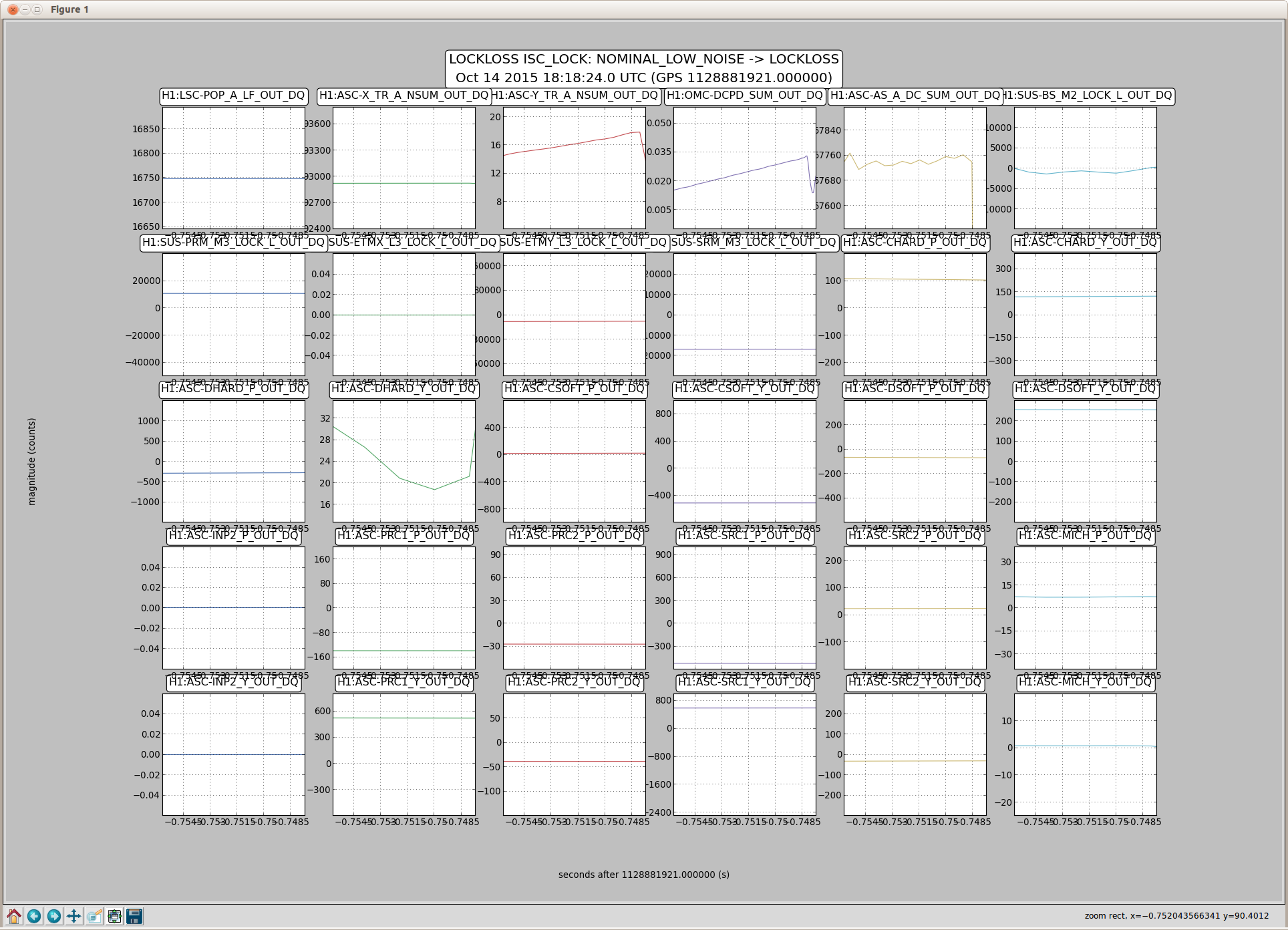
Second plot is the lock loss, and H1:ASC-AS_A_DC_SUM_OUT goes first.
TITLE: 10/14 EVE Shift: 23:00-07:00UTC (16:00-00:00PDT), all times posted in UTC
STATE of H1: H1 was down due to EY temperature variations & passed on to Cheryl to take over.
Incoming Operator: Cheryl
Support: Sheila was consulted over the phone
Quick Summary: Mostly decent shift except for a lockloss toward the end of the shift which is most likely due to temperature variations at EY (see John's alog). I handed over H1 to Cheryl as it was on its way to locking DRMI (no initial alignment was undertaken, only ETMy & TMSy were moved to restore H1 to locking).
Shift Activities:
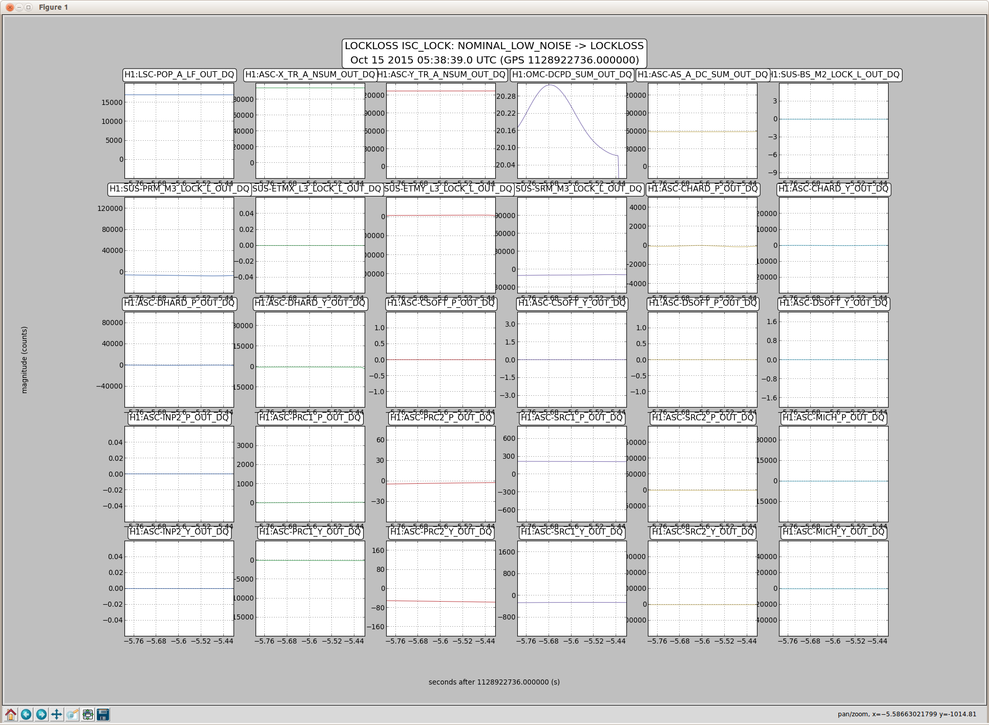
Both lock loss plots show H1:OMC-DCPD_SUM_OUT taking a sudden drop before any other channel shows a glitch.
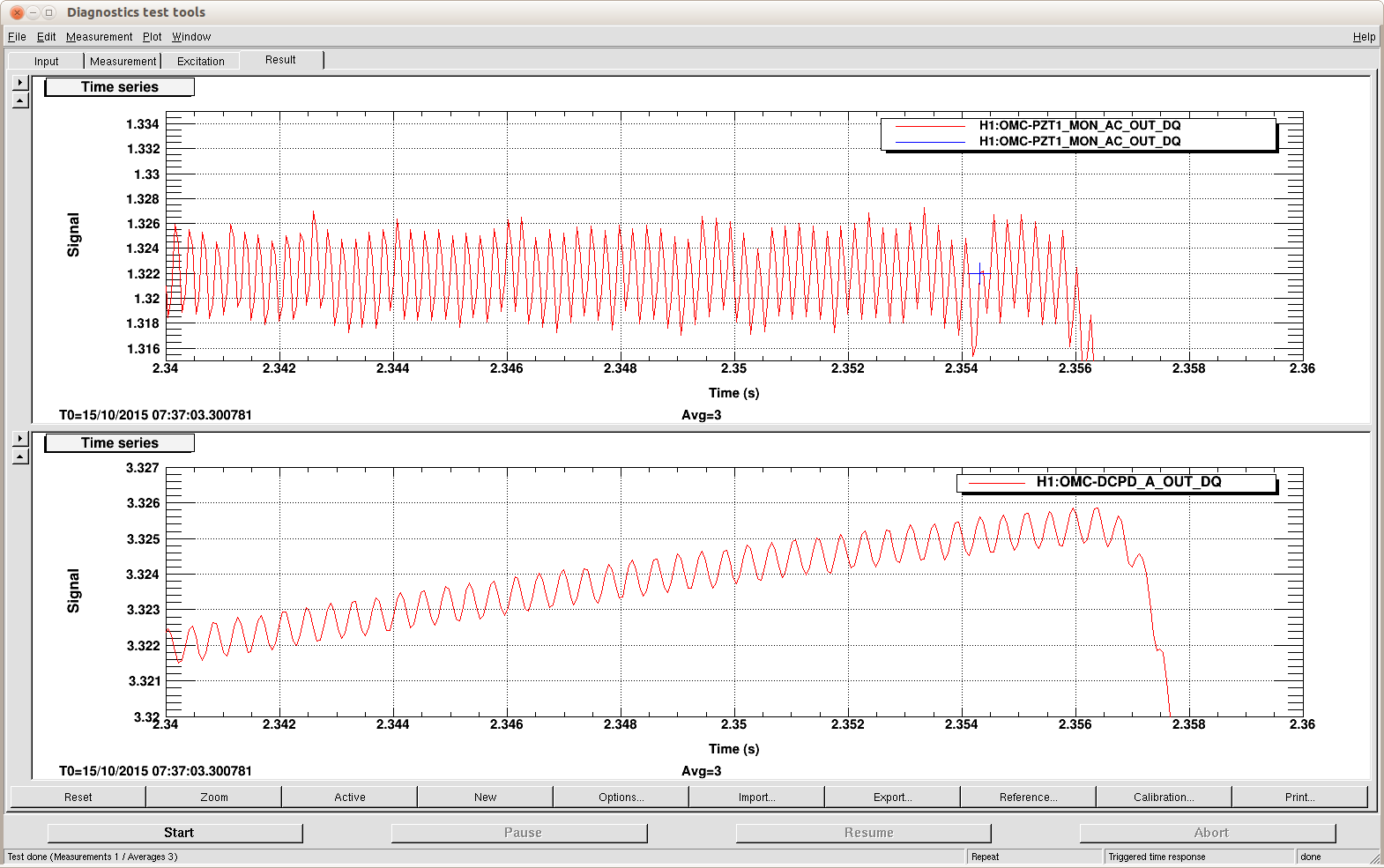
LL@07:37:06UTC - zoom on OMC-DCPD_A_OUT and OMC_PZT1_MON_AC_OUT.
There's something in PZT1 on the plot just after 2.354 on the x axis, where I put the blue cursor, that may be the first glitch.
It's also clear that PZT1 takes off before the OMC-DCPD.
Title: Owl Shift Transition Alog, Owl Shift 07:00-15:00UTC (00:00-08:00PT)
H1 State: Has relocked and made it to Low Noise and Observe, but only lasted 2-3 minutes - Relocked and back in Observe
Outgoing Operator: Corey
Help from: Sheila, Kiwamu
Details:
For the first lock, my interventions:
- I tweaked TMSY to raise the ALS arm power from 0.8 to 1.01
- I tweaked BS to lock DRMI, and then again after DRMI locked in order to get WFS to engage
- IFO went to Low Noise after that without issue
07:34:04UTC - IFO in Observe
07:37:06UTC - lock loss
For the second lock, my interventions:
- I tweaked BS after DRMI locked before WFS engaged
- IFO went to Low Noise after that without issue
08:06:14UTC - IFO in Observe
Issues?
08:07:53UTC - ETMY saturation
08:16UTC - Currently: IFO in Observe and range is 75Mpc
H1 dropped out of lock for no obvious reason, although when it came back, the Yarm looked fairly misaligned. (so assuming the temperature excursion at EY was an issue).
Adjusted ETMy alignment for Locking Arms Green. I was only able to get up to about 0.83. And then at this point, I was stuck. ISC LOCK had the user message: "Waiting for arms to settle". I would also get a flash of a message for ALS COMM of: "COMM PLL or IMC not ready for handoff". Haven't found anything in our Troubleshooting wiki or in Sheila's Operator training document. ALOG searches are a pain and don't yield anything useful.
Have left a voicemail with Kiwamu (On Call).
I don't want to do an Initial Alignment because I don't know whether it's needed and would like to address this ALS issue first.
OK, since I wasn't able to find anything (and I didn't want to randomly start touching anything I waited until hearing back from someone). Sheila called up and said that it would be worth it to try and aligning TMSy (I did not even think of touching it! Mainly because we rarely touch the TMS' during alignments.). I was able to finally get past the Locking ALS step by adjusting the TMSy in Pitch, but now I'm stuck waiting for the Yarm in the CHECK IR step. Frustrating & sad that I have to hand off an unlocked H1 to Cheryl.
Corey, sorry for the delay in my response. I just called the control room. Cheryl responded and she is in the middle of trying to get back to full lock with the newly aligned TMSY. Hopefully we will get back to full lock soon.
I noticed that the End Y temperature was not recoverling after Robert's HVAC shutdowns. Since it appears the chiller was not working correctly I have started the other one. Water temps are now falling. For the record I turned off Chiller 2 and turned on Chiller 1.This is done indirectly by turning the chiller's water pump off or on.We do not control the chiller remotely. There may be some overshoot on the VEA temperature as it corrects - so don't be surprised if it gets cold before it comes back to normal.
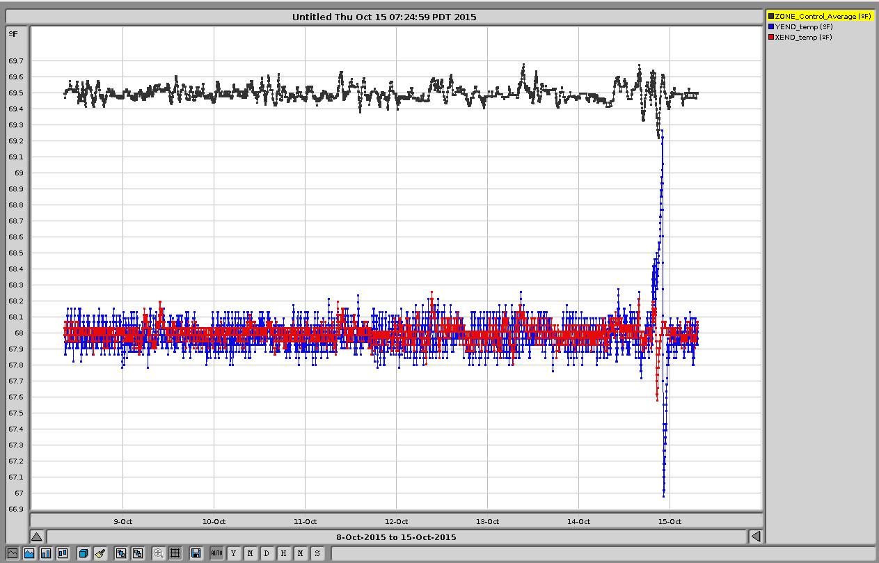
For reference here is a plot showing the temperature excursion which is believed to have caused a lockloss. 7 days shown.
BLUE is the YEND temperature, RED is XEND, and BLACK is the LVEA.
YEND experienced ~ +/- 1degree F of a swing.
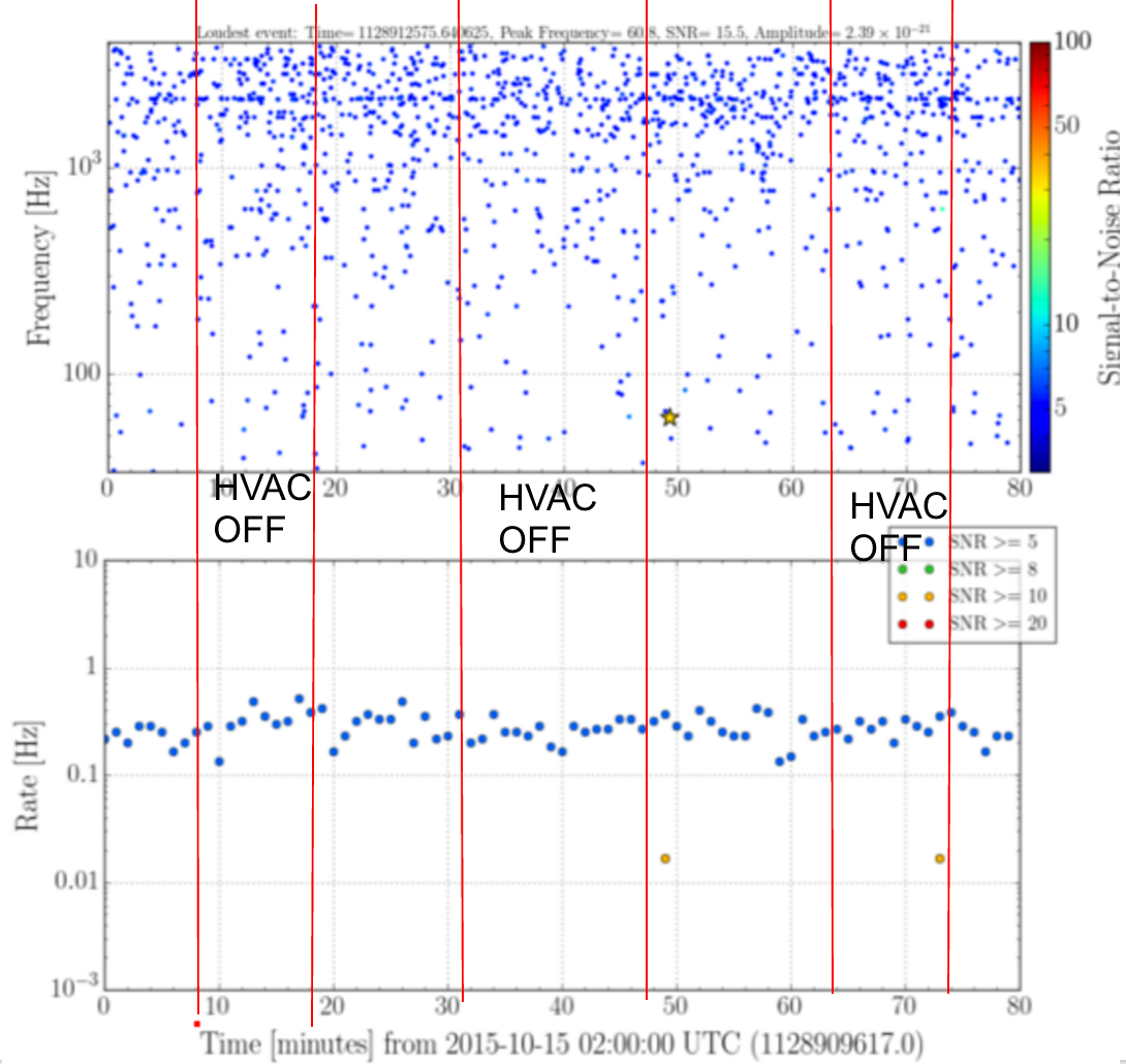
Tamper injections showed some upconversion from the tens of Hz region into the region above 60 Hz. The HVAC makes noise in this region so I did the test I had done in iLIGO, I shut down all turbines and chiller pad equipment on the entire site. This increased the range by almost 5 Mpc (see figure - the 3 range peaks are during the shutoff periods below).
Checks:
1) make sure all VFDs are running at 45 or less
2) if possible use only 2 turbines for the LVEA
We did not drop out of science mode but here are the times of the changes (Oct. 15 UTC):
2:05:00 shutdown started, 2:08:00 shutdown complete
2:18:00 startup started, 2:21:30 startup complete
2:31:00 shutdown started, 2:37:00 shutdown complete
2:47:00 startup started, 2:51:00 startup completed
3:01:00 shutdown started, 3:03:30 shutdown complete
3:13:30 startup started, 3:17:00 startup complete
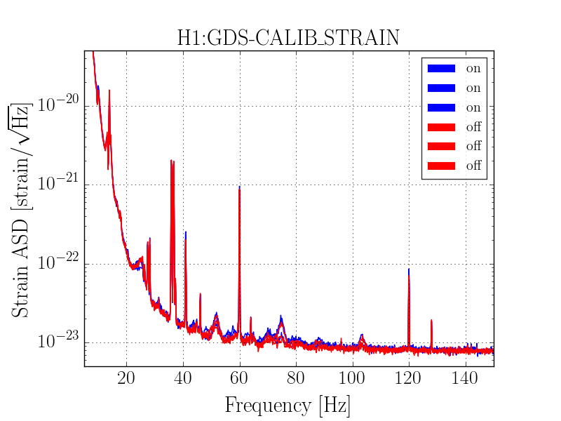
Here is a comparison of the calibrated DARM spectrum from times when the HVAC was ON and OFF, in the frequency band that was affected.
I plotted glitchgrams and trigger rates during this time. Doesn't seem to have made a noticable change.
https://ldas-jobs.ligo-wa.caltech.edu/~jordan.palamos/detchar/HVAC/glitchgram_HVAC_1128909617.png
https://ldas-jobs.ligo-wa.caltech.edu/~jordan.palamos/detchar/HVAC/rate_HVAC_1128909617.png
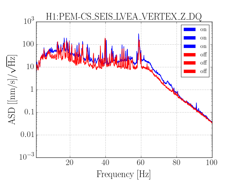
Attached are ASDs of DARM and one of the PEM seismometer channels (corner station Z axis) for all of the times when the HVAC was turned on and off (not including the times of transition). In general, the noise level between 40-100 Hz is lower during the times when HVAC was off. The peak around 75 Hz was better during the second two off times, but not in the first segment. (1128910297 to 1128910697)
More PEM seismometer channels are here: https://ldas-jobs.ligo-wa.caltech.edu/~marissa.walker/O1/Oct15HVACtest/
(note: the seismometer calibration from pem.ligo.org is only valid from 0-20 hz)
TITLE: 10/14 EVE Shift: 23:00-07:00UTC (16:00-00:00PDT), all times posted in UTC
H1's been locked for 8+hrs and in Observation Mode 22:58utc. useism continues to trend down.
Robert took roughly an hour to perform some PEM non-injection work with the HVAC system (basically shutting off fans & chiller yard stuff). With Landry's approval, Robert said we would stay in Observation Mode for these injections. Here are my rough notes on the times:
Darkhan, Sudarshan, GregM, RickS
The plots in the first attached multi-page .pdf file use SLMtool data (60-sec. long FFTs) taken during the month of Oct. so far.
The first page shows the time-varying calibration factors.
The next eight pages have two plots for each of the four Pcal calibration lines (36.7 Hz, 331.9 Hz, 1083.7 Hz, and 3001.3 Hz).
The first of each set shows the calibrated magnitudes and phases of the strain at each frequency (meters_peak/meter).
The second plot in each set shows ratios (mag and phase) of the three methods (Cal/Pcal, GDS/Pcal, and Cal/GDS). The center panels (GDS/Pcal) are most relevant because we expect discrepancies arising from the CAL_DeltaL_External calculations not including all the necessary corrections.
The plots in the second multi-page .pdf file show the GDS/Pcal ratios at the four Pcal line frequencies over the time period from Oct. 7 to Oct. 11, with histograms and calculated means and standard errors (estimated as standard deviation of the data divided by the square root of the number of points).
Note that these time-varying factors (kappa_tst and kappa_C) have NOT been applied to the GDS calibrations yet, so we expect the GDS/Pcal comparisons to improve once they are applied.
The difference of ~9% in 3 kHz line (mean value) probably comes from the foton IIR filtering which is ~10% at 3 kHz i.e., the front-end DARM is 10% higher than the actual value. SInce online GDS (C00) is derived from output of front-end model, it would also show similar difference. However the offline GDS (C01 or C02) corrects for this and hence expect not to show this difference.
Travis and Darkhan's calibration measurements made two days ago indicated that the clipping observed at Xend is getting worse.
We think this reduction is almost completely one beam and that the reduction in Rx power is taking place on the Rx side of the ETM (more on this later).
We expect to go inside the vacuum envenlope and investigate at our next opportunity. In the meantime, we are switching to using the Tx PD rather than the Rx PD for calibration.
We need to make this switch for calibrating the hardware injections too.
In the first attached plot, SLM-tool data, 60 sec.-long TTFs of the Pcal Rx and Tx PD signals is plotted, the receiver side (Rx) data divided by the transmitter side (Tx) data.
The second plot is a comparison of the GDS calibration to the Pcal calibration at 3 kHz using the Rx PD, and the Tx PD in the last plot.
The mean magnitude ratio using the Rx PD is about 14%. It is 8% using the Tx PD.
TITLE: 10/14 EVE Shift: 23:00-07:00UTC (16:00-00:00PDT), all times posted in UTC
STATE of H1: Taken to Observation Mode @75Mpc during Operator hand-off. Current lock going on 5hrs.
Outgoing Operator: Jim
Support: Occupied Control Room, Kiwamu is On-Call if needed
Quick Summary:
All looking quiet on the seismic front (useism low, EQ band also low, & winds are under 10mph).
Jim walked me through/reminded me how to address low (under 8%) ISS Diffracted Power by tweaking the REFSIGNAL slider.
Robert also wanted me to keep him posted on any possible FMCS alarms (since he's been making HVAC changes). He mentioned possibly doing more of this work if time allows.
Jenne also walked me through running the A2L scripts every time before going to Observation Mode per her alog (WP22524).
Operators,
As part of WP 5552, we'd like to run the A2L script several times over the next week. I have modified the script such that it will put all settings back to what they were, so the configuration of the IFO won't change (normally when we run A2L, it will change some gains that we must make a decision on whether or not to accept). I've also incorporated the "stop_osc" script that finishes clearing the SDF diffs, so this should be a one-liner no muss, no fuss operation. The script takes less than 2 minutes to run.
So, after reaching NOMINAL_LOW_NOISE but before hitting the Observe intent, please run the following:
cd /opt/rtcds/userapps/release/isc/common/scripts/decoup
./a2l_min.py
We'd like to do this at the beginning of every lock stretch for about the next week. If you're ending a commissioning / maintenence / other period and about to go to Observe but the IFO stayed locked, or are about to go into one of those periods but the IFO is still locked, that would also be a good time to run the code, so that we get even more data after the IFO has had time to settle. But please do not drop out of Observe just to run this measurement.
The code should clear all the SDF diffs, but if anything is left over, please revert everything, so that the state of the IFO isn't changing.
TITLE: 10/14 day Shift: 15:00-23:00UTC
STATE of H1: Low-noise for 4 hours, periodic commissioning during single IFO time
Support: Usual control room population
Quick Summary:
Quiet, busy shift with lots of noise investigations, H1 was well behaved
Shift Activities:
16:04 lockloss
18:03 LLO has a bounce mode rung up, so we go to commissioning
18:05 Evan turning on BLRMS filters, Richard to EY, Robert to LVEA
19:00 Gerardo to EX, JeffB to LVEA
19:00 Robert to EX for tamping
21:10 JeffB to LVEA
21:00 Evan trying some BLRMS filters
22:30 Robert turning HVAC off, done 22:50
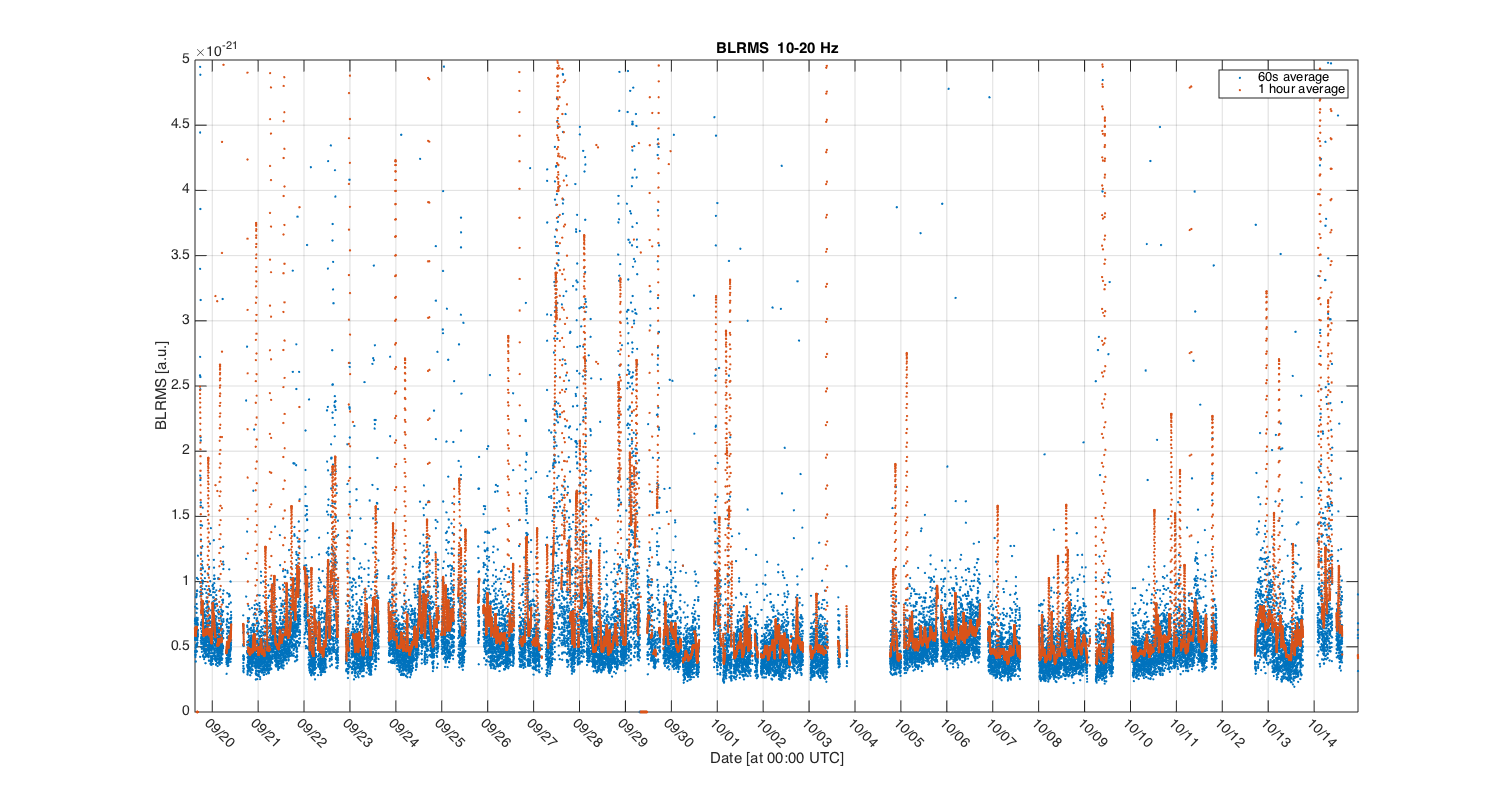
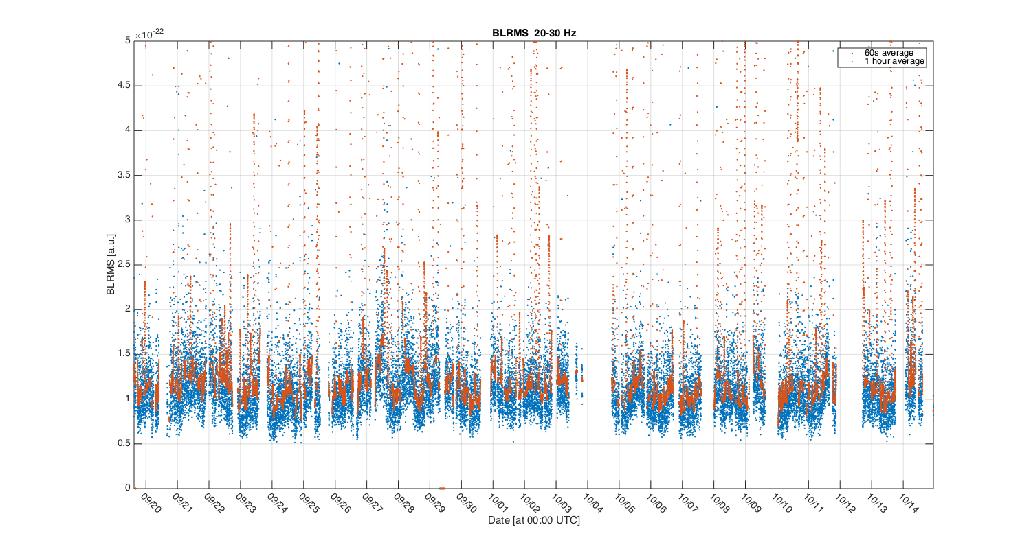
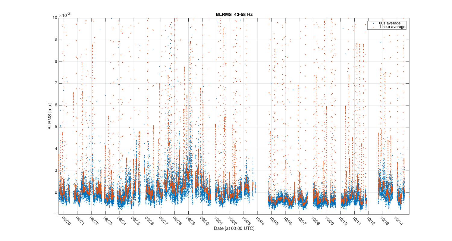
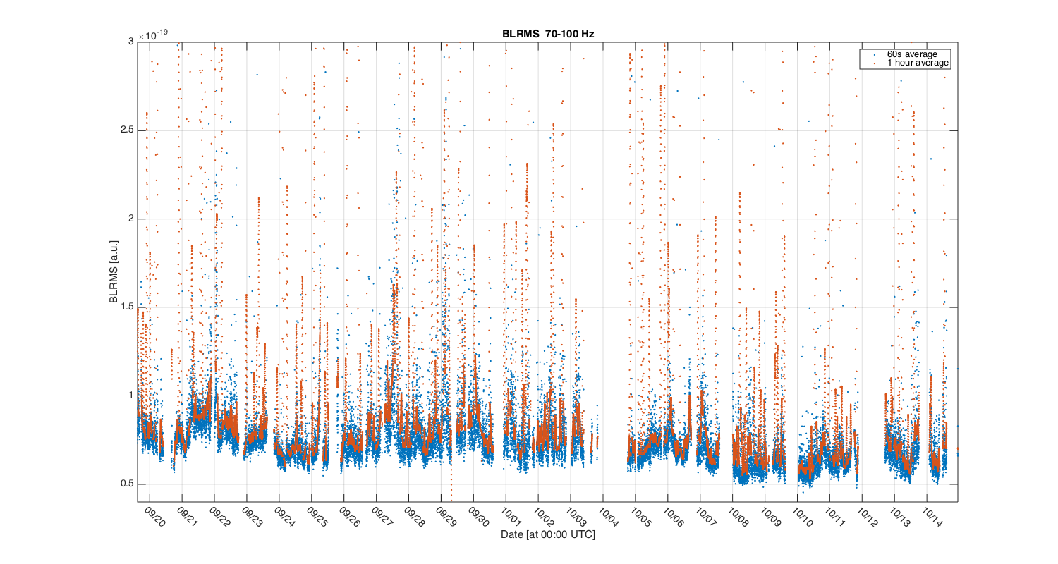
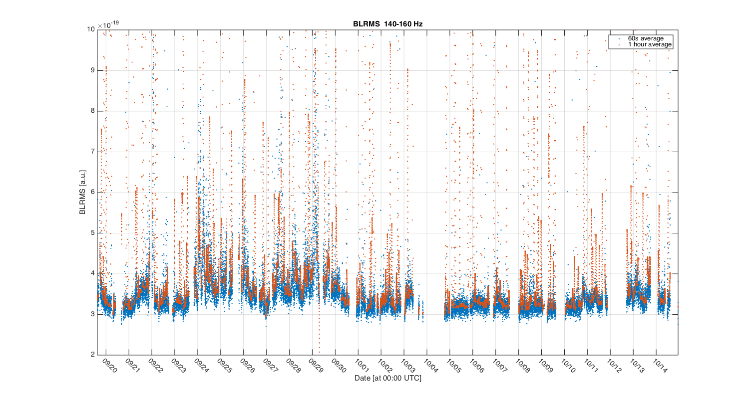
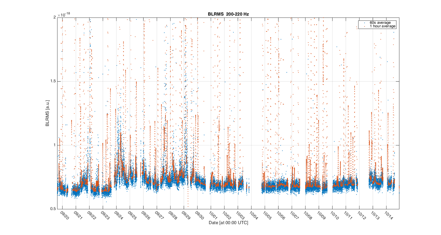
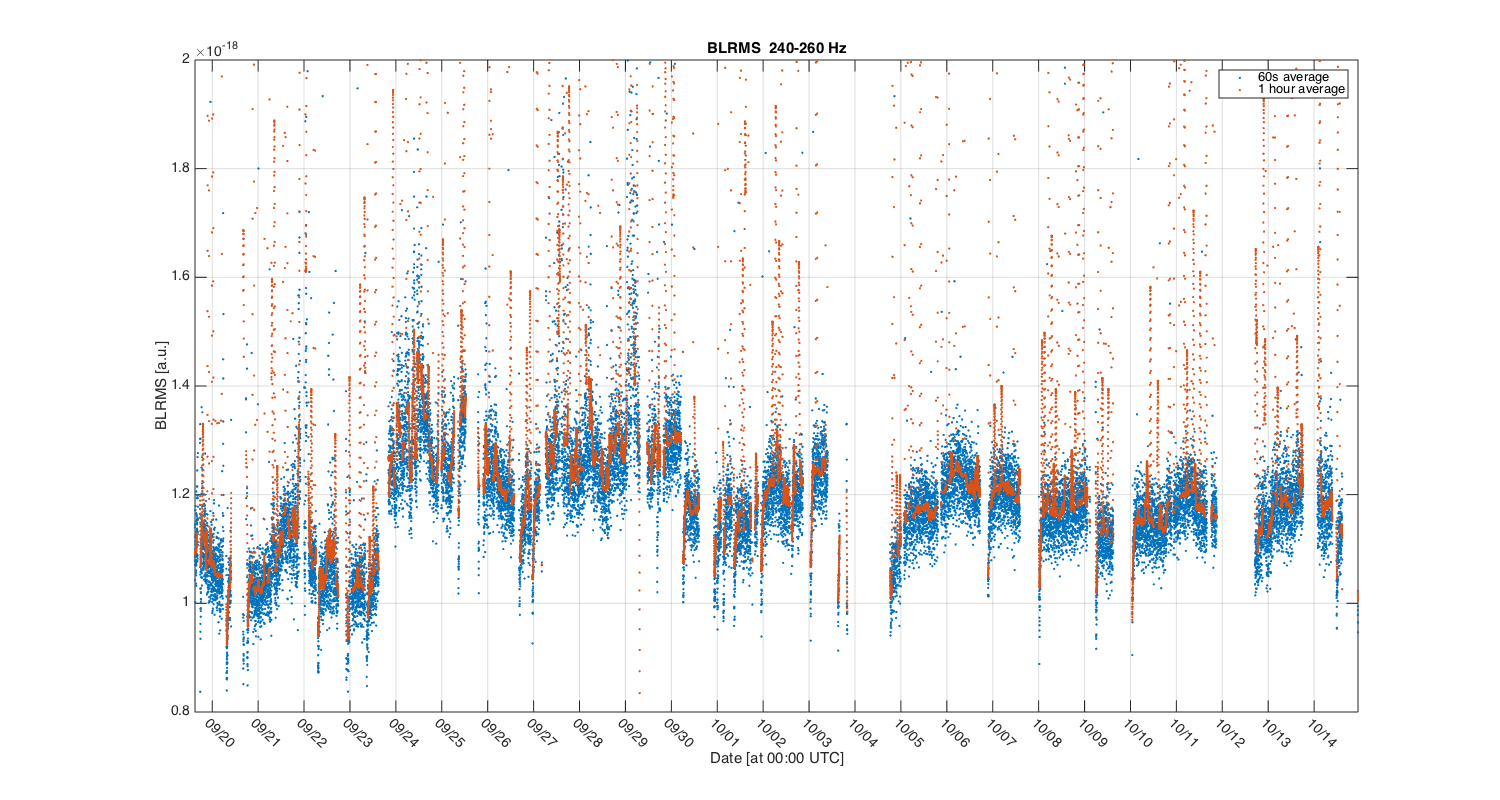
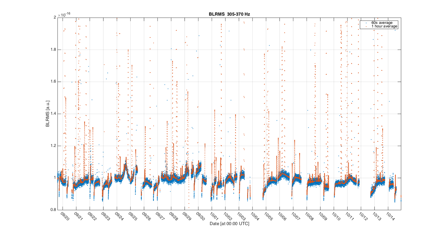
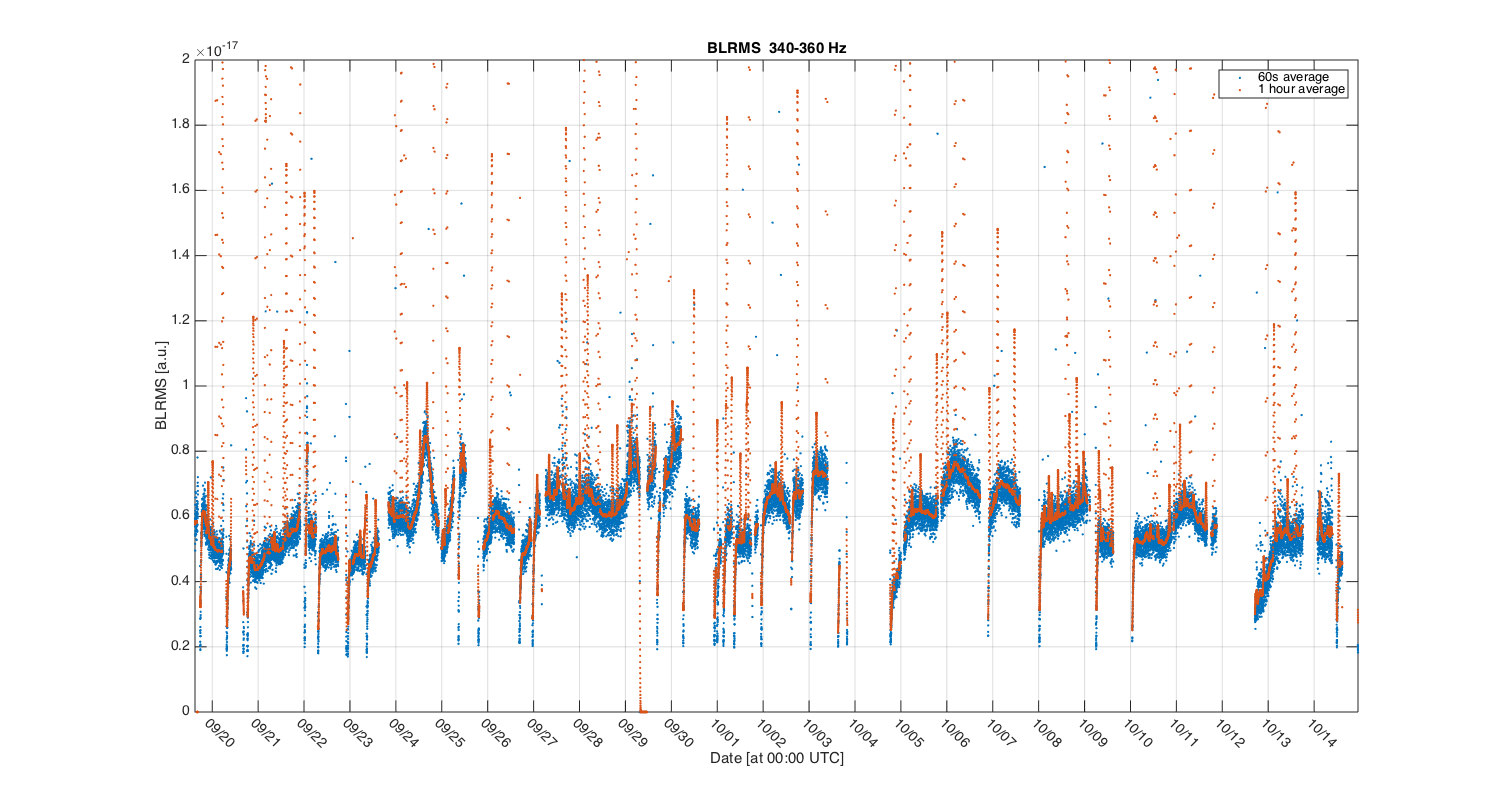
The plots attached to this elog show the trend of the LHO detector noise over the O1 time span so far. Each plot shows the band-limited RMS of the CAL-DELTAL_EXTERNAL signal, in a selected frequency band. I didn't apply the dewhitening filter. The BLRMS is computed over segments of 60 seconds of data, computing the PSD with 5s long FFTs (Hann window) and averaging. The orange trace shows a smoothed version, averaged over one hour segments. Only time in ANALYSIS_READY have been considered.
The scripts used to compute the BLRMS (python, look at trend_o1_fft_lho.py) are attached and uploaded to the NonNA git repository. The data is then plotted using MATLAB (script attached too).
I think there's a lot of interesting information in those plots. My plan would be to try to correlate the noise variations with IFO and environmental channels. Any suggestion from on-site commissioners is welcome!
Here are my first comments on the trends:
So what happenend on September 23rd around the end of the day, UTC time?
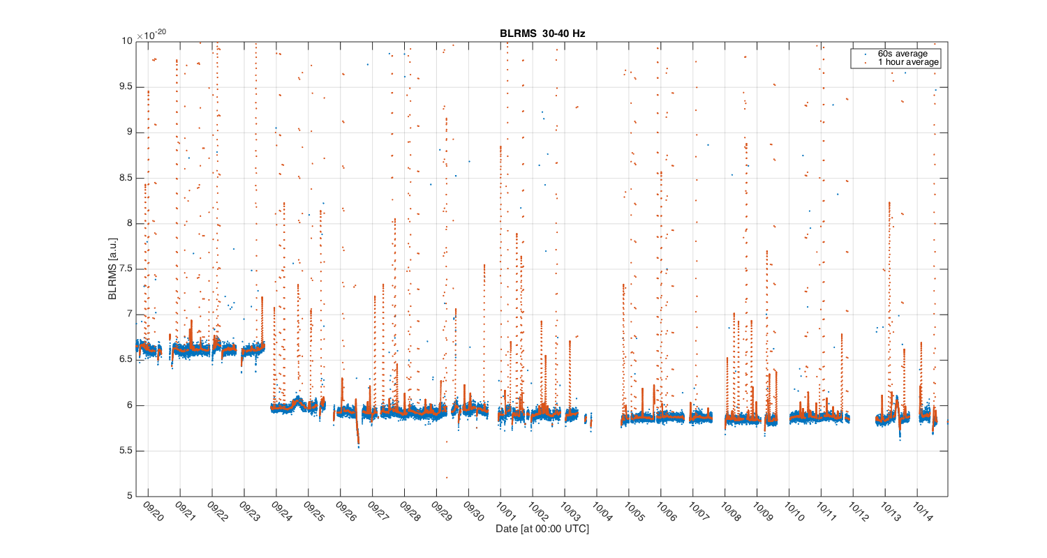
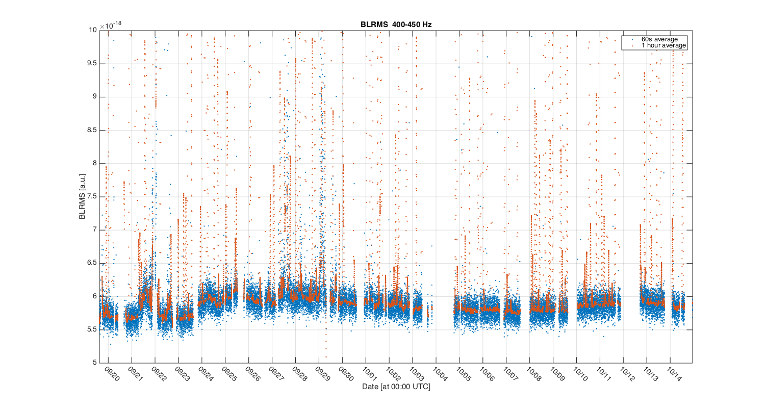
S. Dwyer, J. Kissel, G. Vajente

Gabriele notes a drop in BLRMS that is most (only) visible in the 30-40 [Hz] band, and questions what happened around Sept 23rd.

Sheila (re)identified that I had made a change to the calibration that only affects DELTAL_EXTERNAL around the day, see LHO aLOG 21788.

This change, increasing the delay between the calibrated actuation and sensing chains just before they're added, would indeed affect only the region around the DARM UGF (~40 [Hz]), where the calibrated actuation and sensing functions are both valid, and roughly equal in contribution to the DELTAL_EXTERNAL signal. Indeed, the (6.52 - 6)/6 = 0.086 = 8% drop is consistent with the 8% amplitude change expected that Peter describes in his motivation for me to make the change of the relative delay, see LHO aLOG 21746.

Gabriele has independently confirmed that he's using DELTAL_EXTERNAL (and not GDS-CALIB_STRAIN which would *not* have seen this change) and the change happened between Sept 22 2015, between 15:00 and 20:00 UTC (*not* Sept 23rd UTC that he mentioned above). I've confirmed that the EPICs record was changed right smack in between there on Sept 22 17:10 UTC.

Good catch, Sheila!
Jordan, Sheila
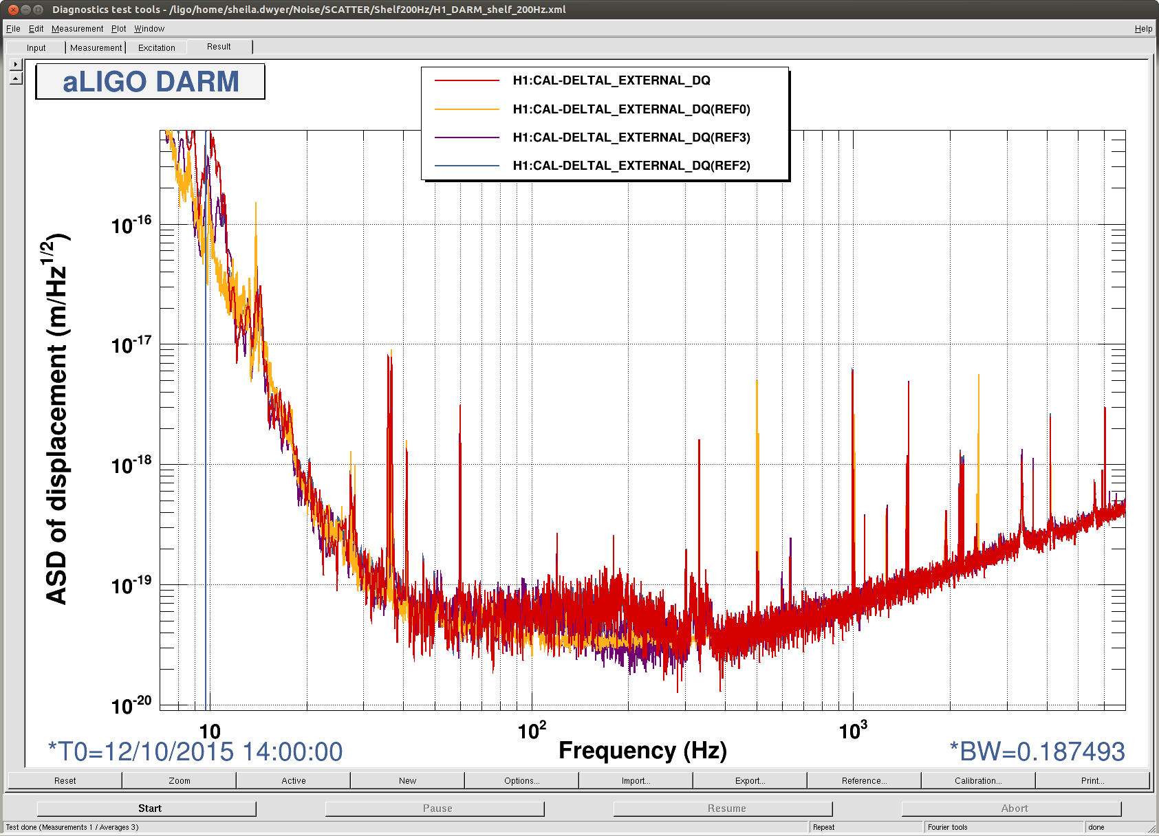
In the summary pages, we can see that something non stationary appeared in DARM from about 80-250 Hz durring the long lock that spanned Oct 11th to 12th, and has stayed around. Links to the spectra from the 11th and the 12th.
HVETO also came up with a lot of glitches in this frequency span starting on the 12th, (here) which were not around before. These glitches are vetoed by things that seem like they could all be realted to corner statin ground motion: refl, IMC and AS WFS, all kinds of corner station seismic sensors, PEM accelerometers, MC suspensions.
Although this noise seems to have appeared durring a time when the microseism was high for us, I think it is not directly related. (high microseism started approximately on the 9th, 2 days before this noise appeared and things are quieting down now but we still have the non stationary noise sometimes up to 200 Hz.)
The blend switching could also seem like a culprit, but the blends were not switched at the begining of the lock in which this noise appeared, and we have been back on the normal (90mHz blends) today but we still have this noise. We've seen scattering from the OMC with velocities this high before (17264 and 19195).
Nutsinee and Robert have found that some of the glitches we are having today are due to RF45, but this doesn't seem to be the case on the 12th.
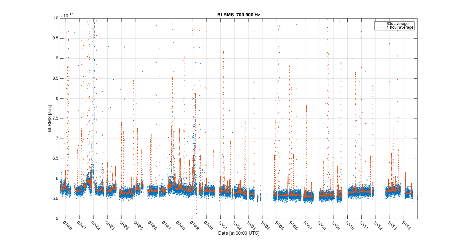
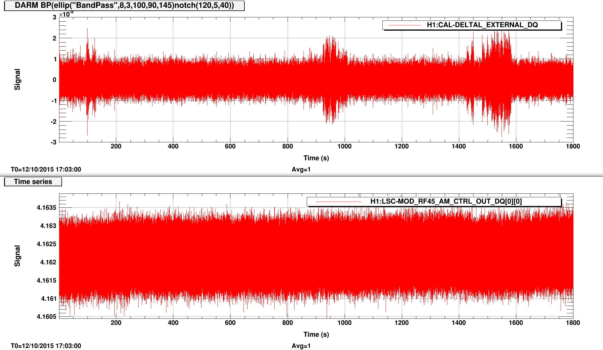
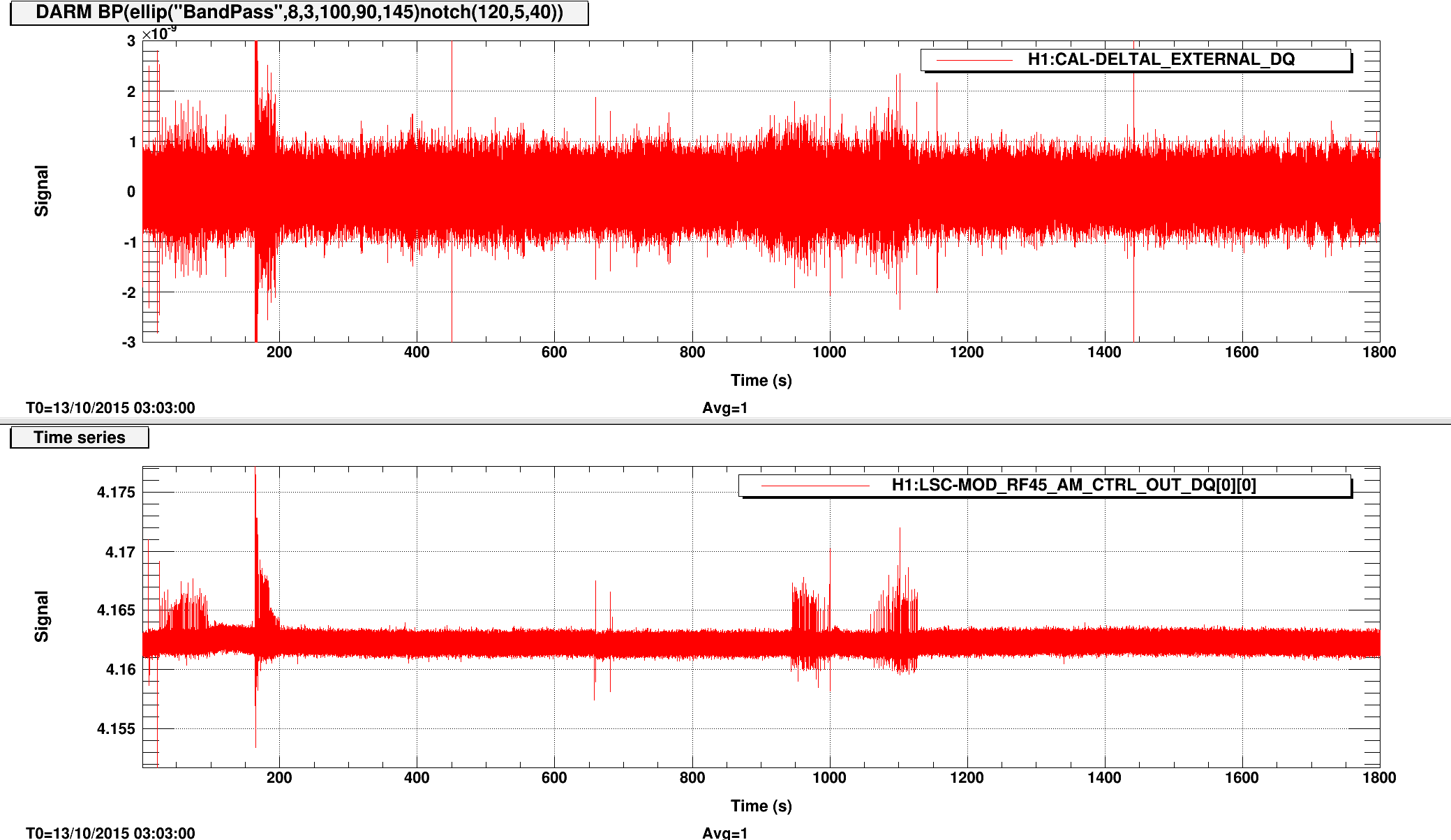
Robert, Sheila, Nutsinee
The first plot attached is a timeseries of DARM vs RF45 mod of the 10/11 - 10/12 lock stretch (~25 hours). The second plot is the same channels during the beginning of 10/13 lock stretch (30 minutes). You can see RF45 started to act up on 10/13. I've also attached the BLRMS plot of DARM using the bandpass filter Robert used to find the OMC scattering. The none stationary noise we see is likely caused by two different sources.
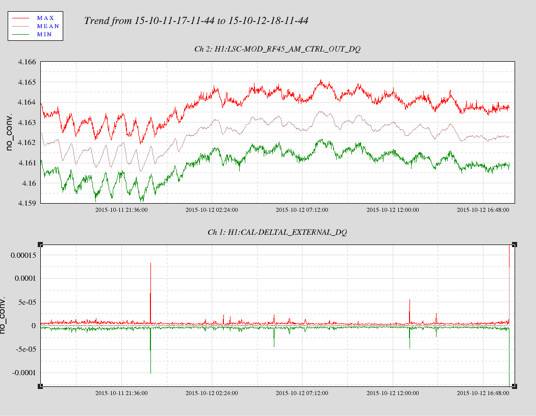
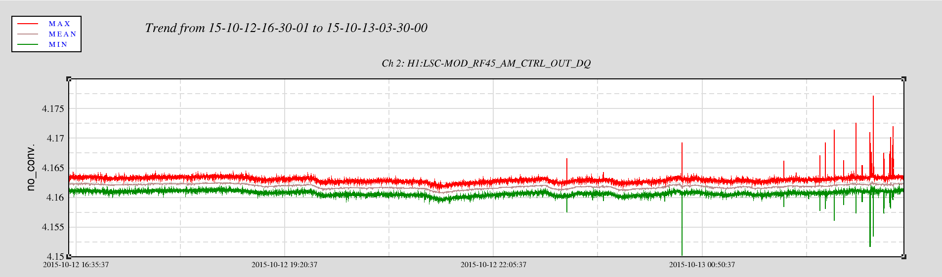
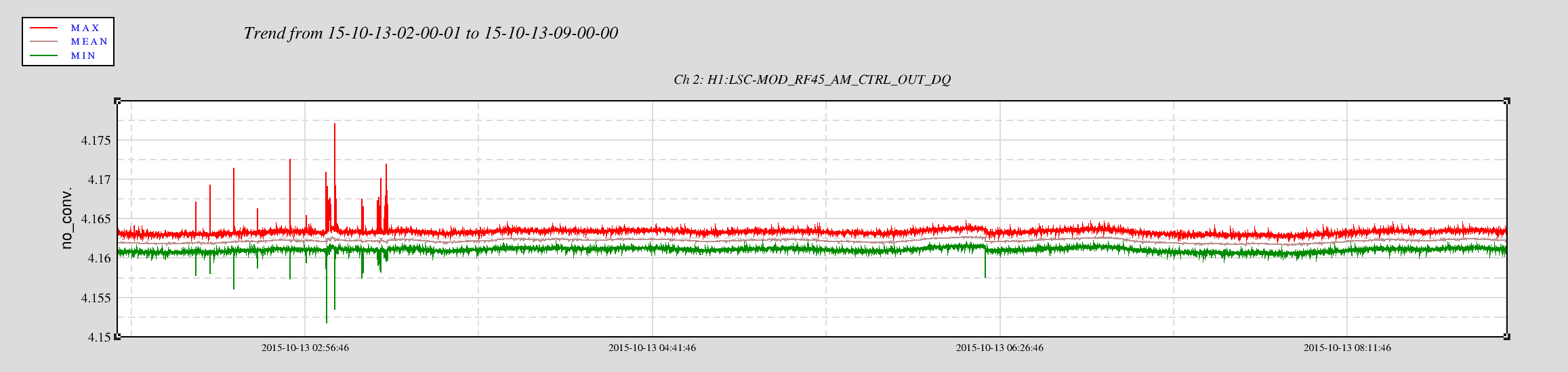
RF45 started to glitch Monday afternoon (16:04 PDT, 23:04 UTC). According to TJ's log no one was in the LVEA that day. The glitches stopped around 03:22 UTC (20:22 PDT)
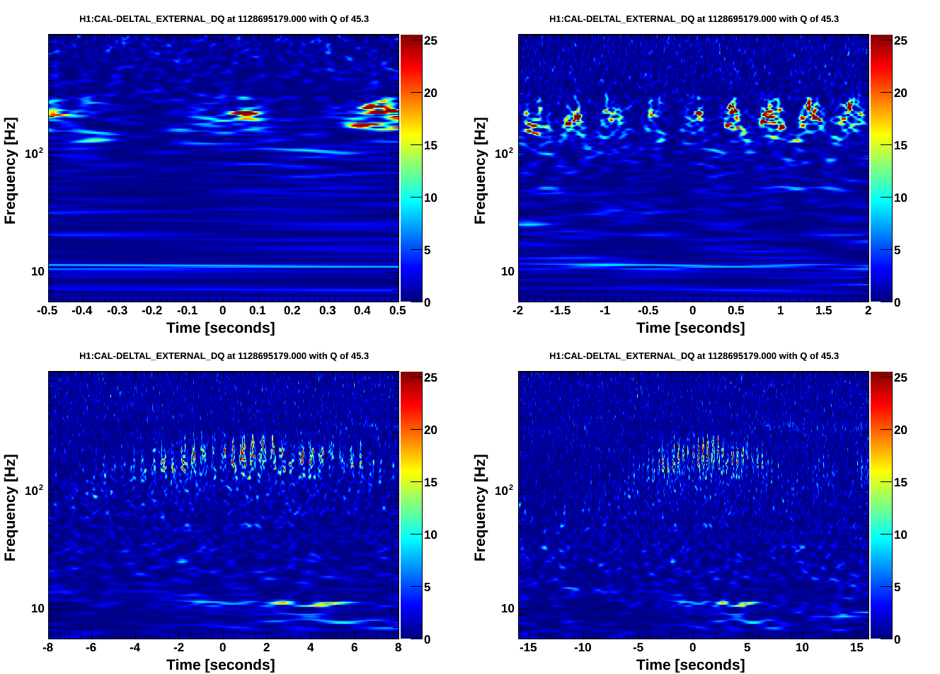
Here is one example of one of these glitches rlated to ground motion in the corner that we had durring high microseim over the weekend (but not the entire time that we had high mircoseism). This is from Oct 12th at 14:26 UTC. Even though these have gone away, we are moitvated to look into them because as Jordan and Gabriele have both confirmed recently, the noise in the unexplained part of the spectrum (50-100 Hz) is non stationary even with the beam diverter closed. If the elevanted ground motion over the weekend madde this visible in DARM up to 250Hz, it is possible that with more normal ground motion this is lurking near our sensitivity from 50-100 Hz.
If you believe these are scattering shelves.
See josh's alogs about similar problems, especially 19195 and recently 22405
One more thing to notice is that at least in this example the upconversion is most visibe when the derivative of DARM (loop corrected) is large. This could just be because that is the time when the derivative of the ground motion is large.
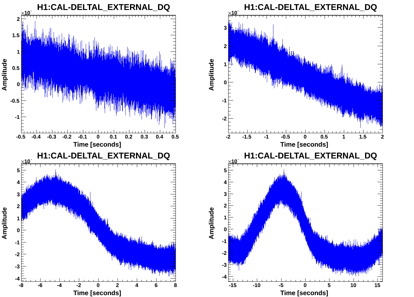
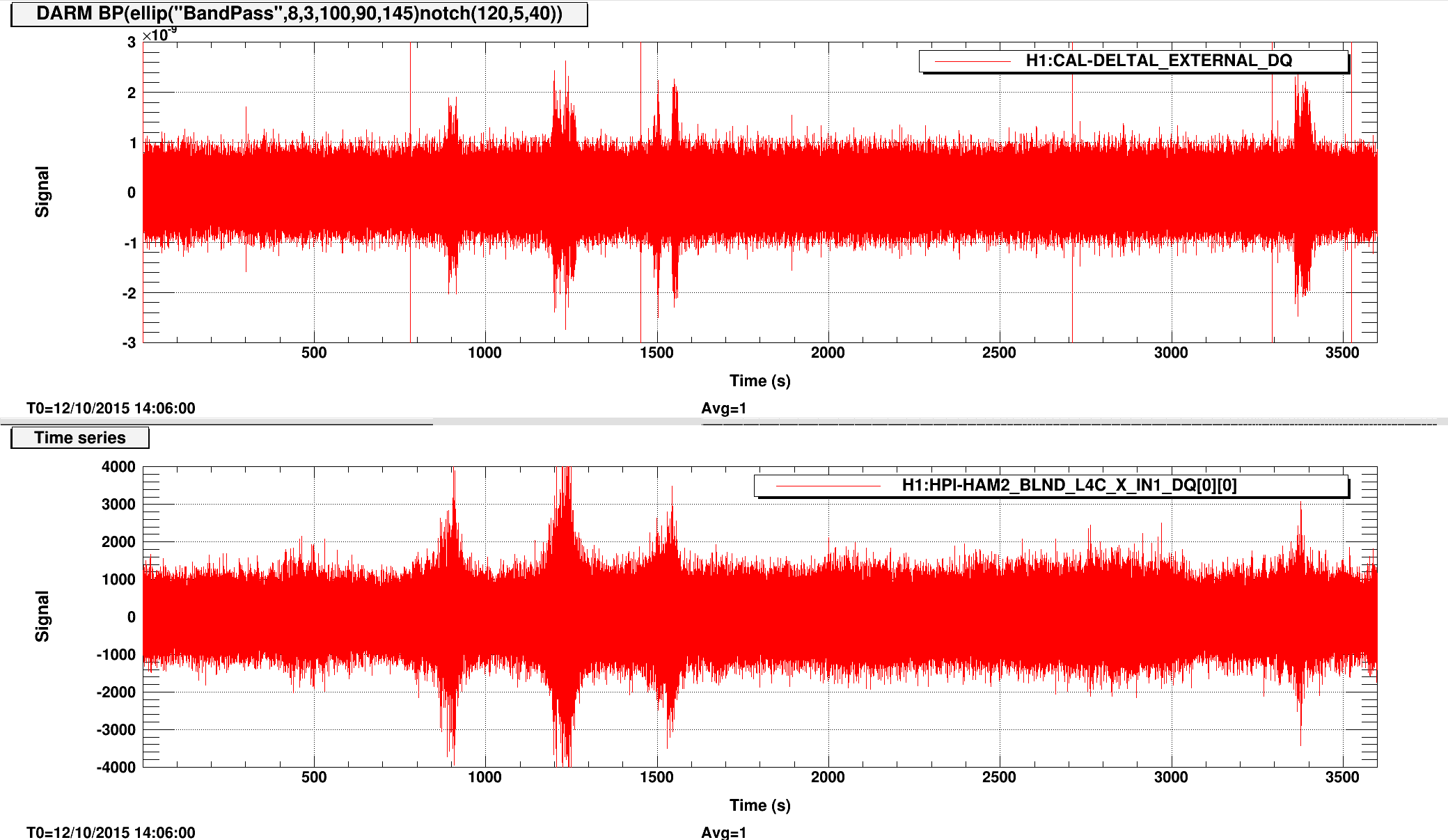
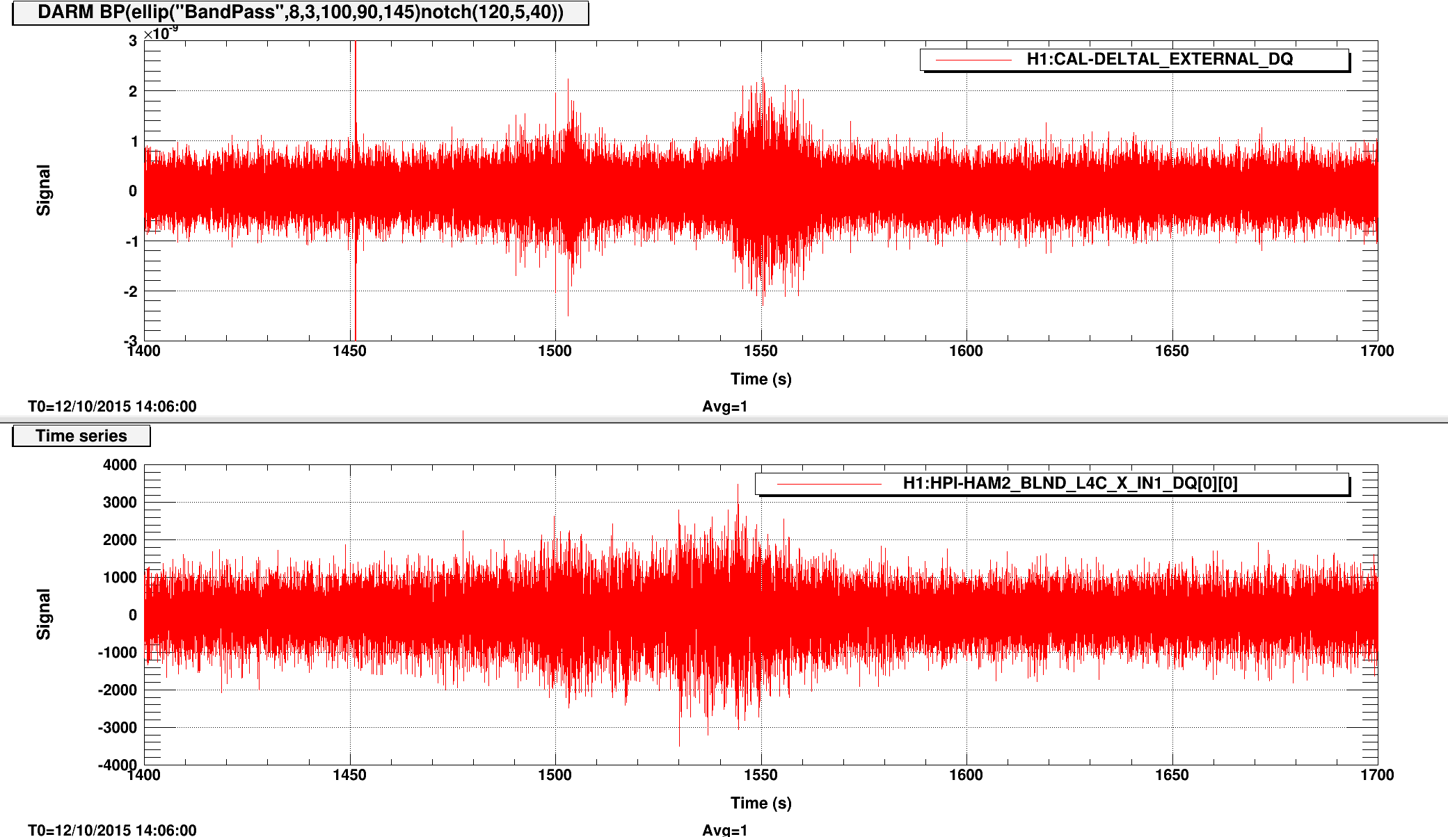
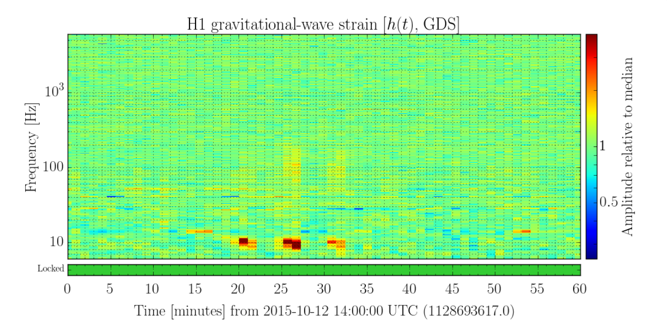
Nairwita, Nutsinee
Nairwita pointed out to me that the non-stationary glitches we're looking at was vetoed nicely by HPI HAM2 L4C on October 12th, so I took a closer look. The first plot attached is an hour trend of DARM and HPI HAM2 L4C. But if I zoom into one of the glitches it seems to me that there's a delay in response between HPI and DARM up to ~10 seconds from just eye-balling it (second plot). I've also attached the spectrogram during that hour from the sumary page.


