I had a look at locklosses durring the last week of ER 8 (Sept 10 to 17th) The mesage is that loose and cross coupled angular controls that can't handle increased ground motion seem to be contributing to most of our locklosses (at least 15 out of 18).
There were 22 locklosses durring this time, I discarded 4 of them because of commisioning activites: (1125897235.18750 (ASC commisioning) 1125951730.31250(ASC commisioning) 1125996518.31250 (ASC commisioning) 1126229152.18750 (not really a lockloss) 1126251273.81250 (AS Bdiv open, probably beam jitter measurements))
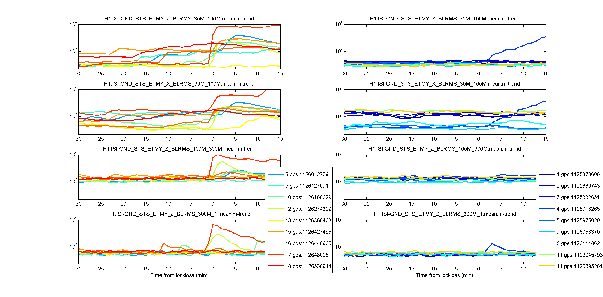
Of the remaining 18 locklosses, 9 were within 5 minutes of an earthquake arriving on site, and a tenth had an earthquake showing up on the 30-100 mHz blrms 5-10 minutes after the lockloss. 5 more of the locklosses were at times when there was no earthquake but the ground was tilting probably due to wind. (The z direction ground motion was quiet but the X direction was moving).
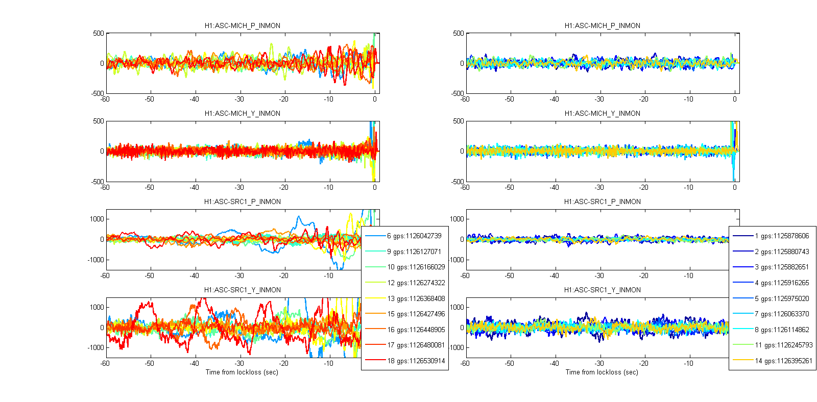
Most of the earthquake locklosses where ones in which the ASC error signals were not well supressed for 10s of seconds before the lockloss. The first attachment shows how I sorted the locklosses into ones where some ASC error signals were clearly not supressed, and others where there was no obvious problem in the error signals for 10s of seconds before the lockloss. The second attachment shows plots of the ground motion at the time of lockloss with the same sorting of locklosses into bad ASC/ OK ASC.
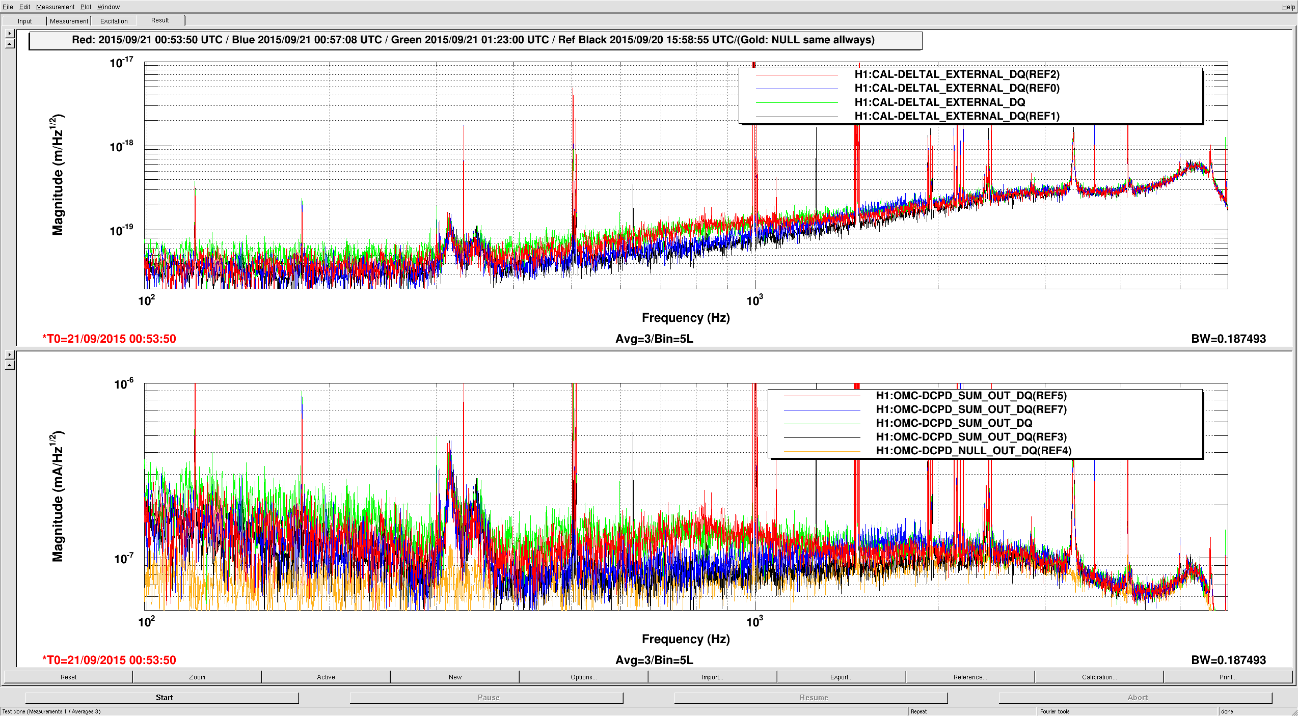
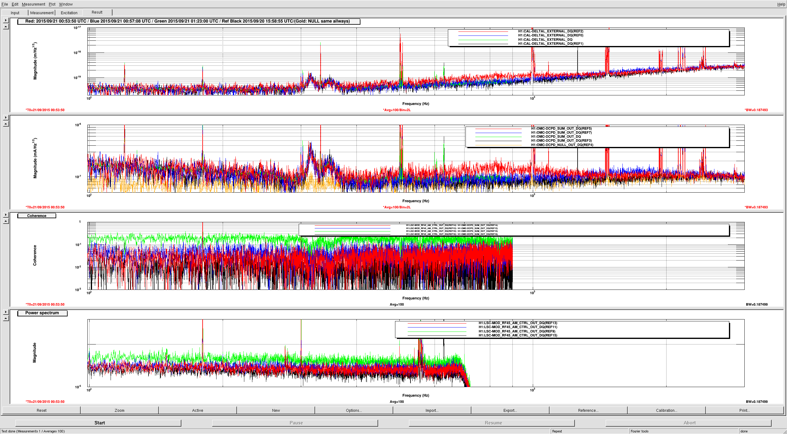
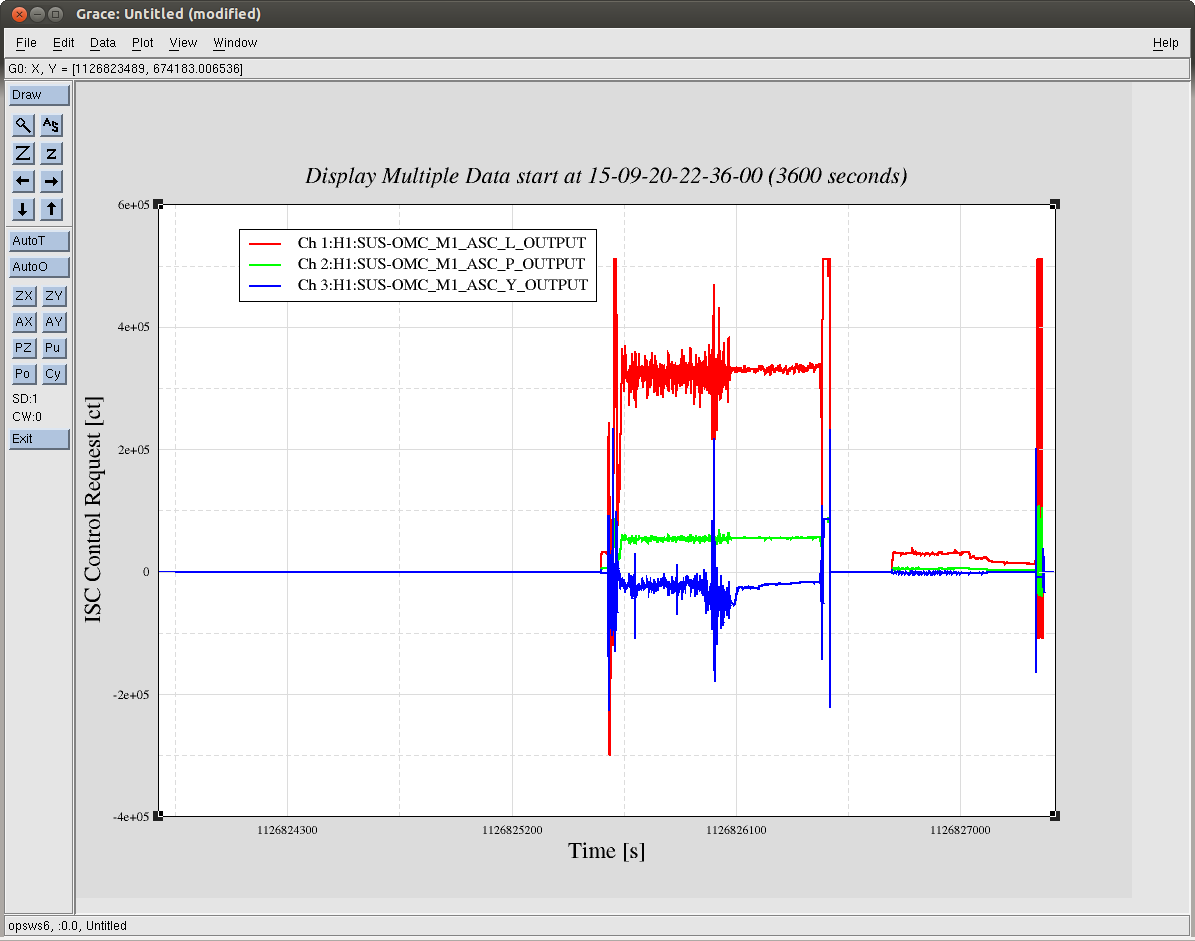
Next I plotted all the ASC error signals (normalized by a max of each) on one plot for pit and one for yaw for each lockloss. I won't attach all those plots, but generally yaw went bad earlier than pitch and DHARD yaw was one of the first error signals to wander away in almost all of the locklosses. We have a boost (FM3) available for DHARD Y that we aren't currently using, and plently of phase margin available to turn it on 20084. Turning this on seems like the very first step we should take in trying to ridde out ground motion better. If any operators see an earthquake coming they might as well try this. Also if you need to leave observation mode or relock, you might as well try engaging this boost.
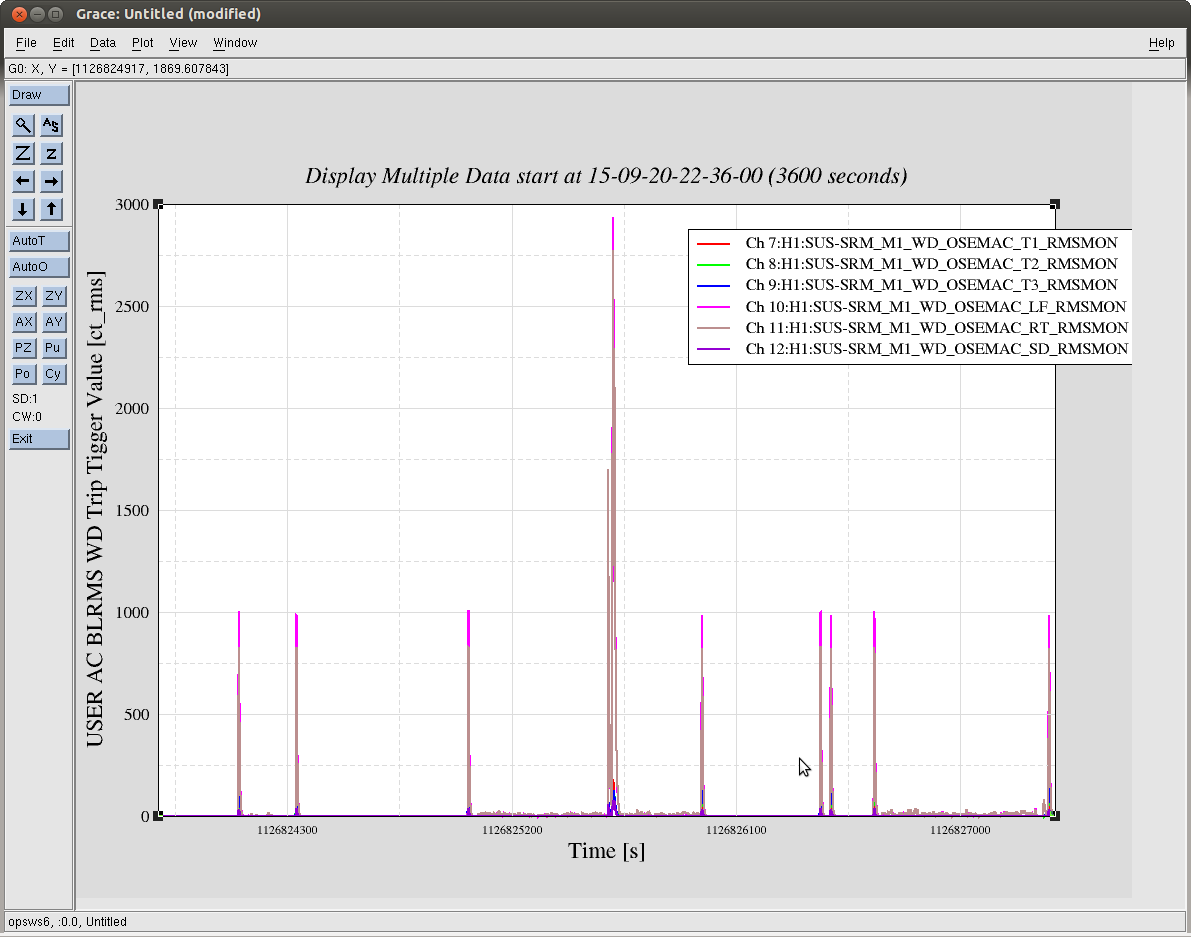
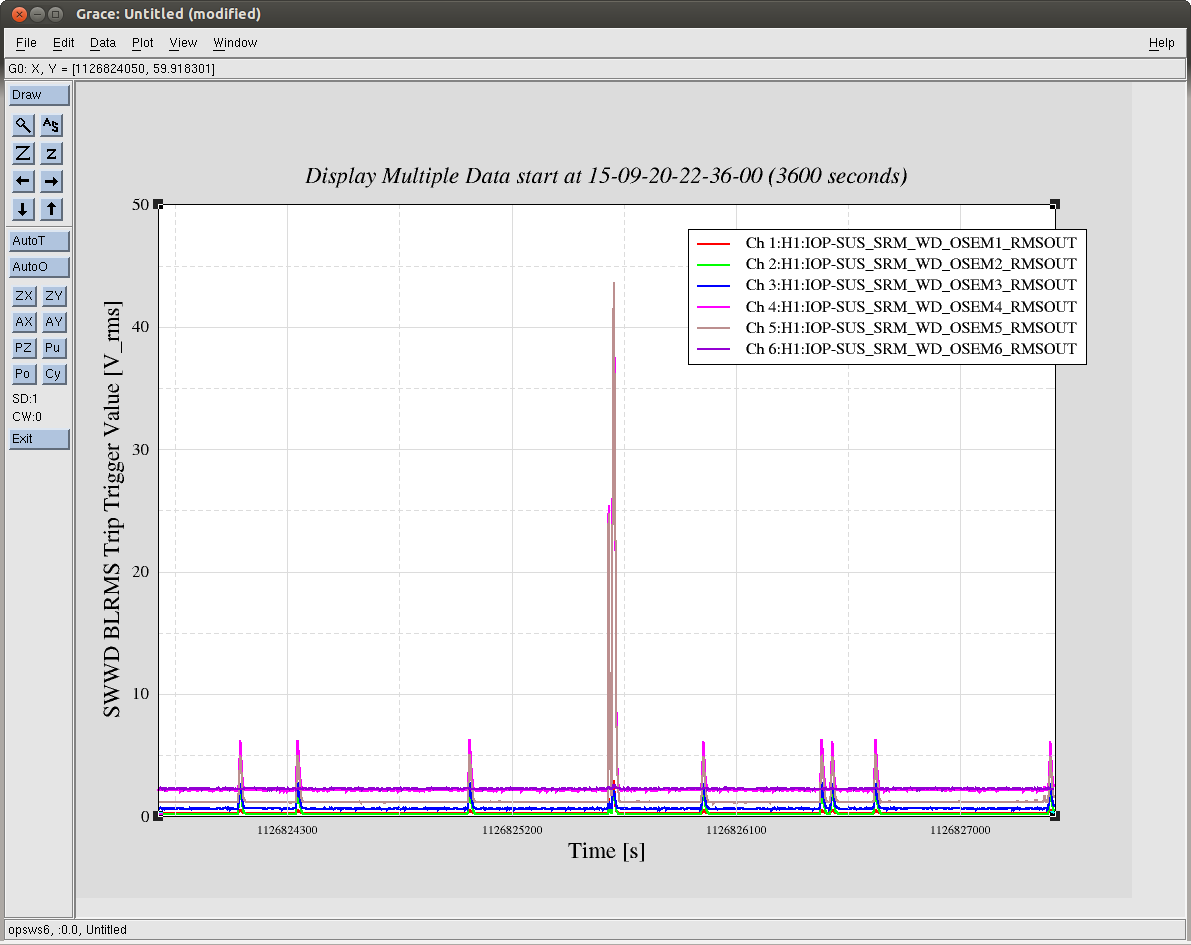
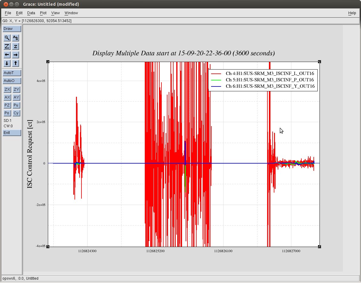
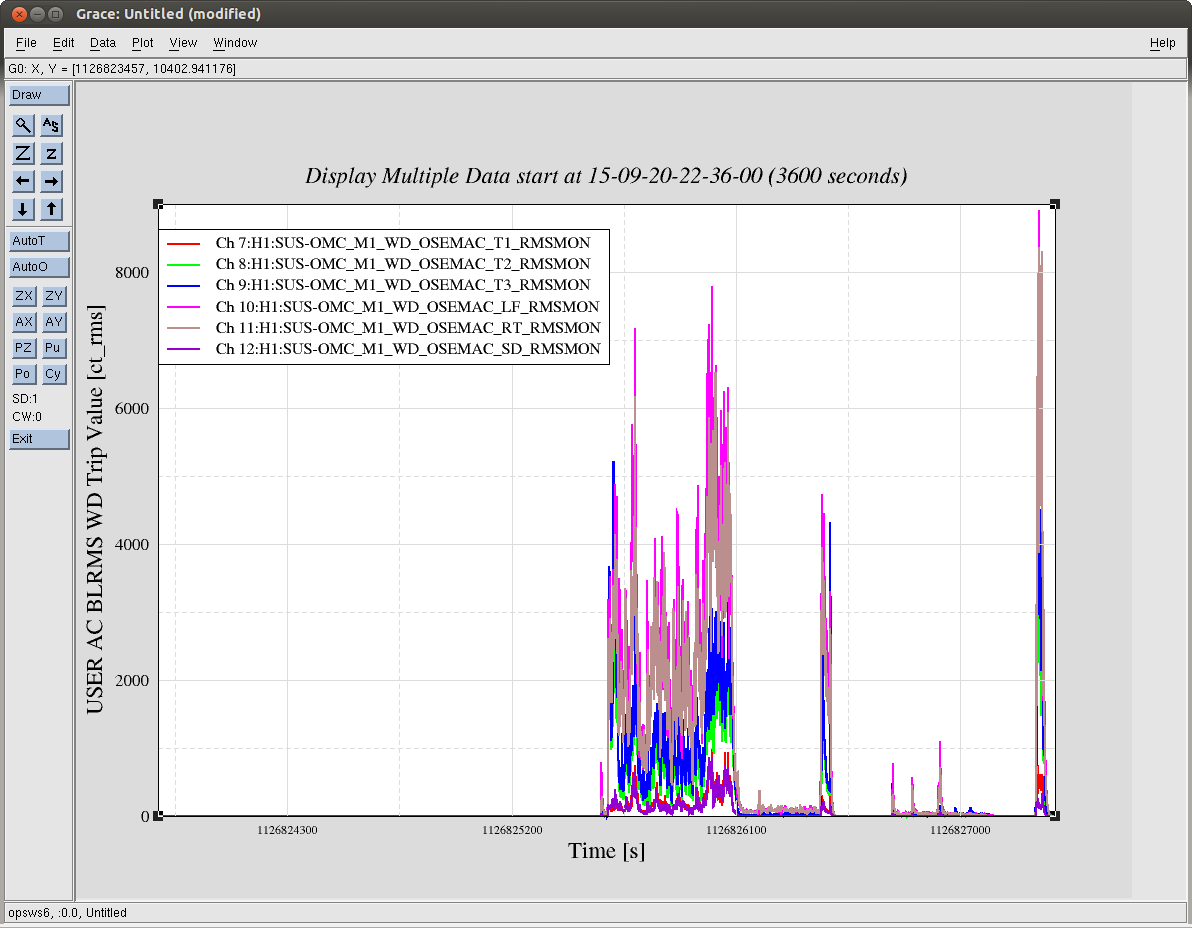
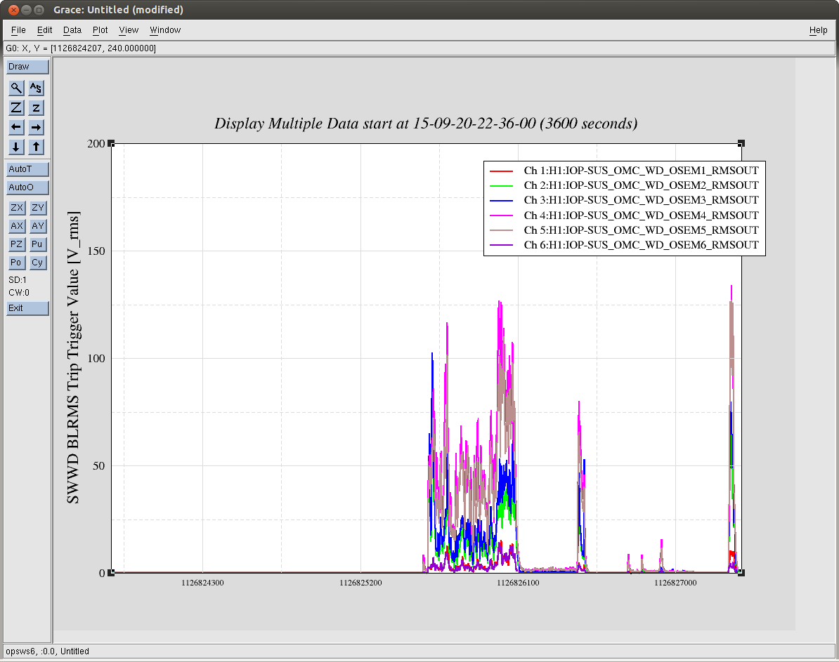
I also looked at saturations for 9 of the earthquake locklosses, severa of them seem to have no saturations until after the lockloss. A few have saturations of ETMY, there is a pitch oscillation that grows in the final seconds of the lock making the L2 control signal large. The L3 length control signal responds to this and can also become large. There were a few locklosses where SRM M3 saturates because of a large pitch drive.
The next steps I would propose are to engage the DHARD yaw boost first (this should be safe and only take seconds). After that, it would be good to continue trying to decouple our ASC loops better by phasing the REFL 45 WFS, and using them to control the SRC ASC. This is a project that is probably best done at 3 Watts and whenever we can set aside a few hours for commisioning. It doesn't seem like saturations from length loops are much of a problem for us now, so we can probably not worry about that for now.