• This DQ shift was fairly uneventful. The duty cycle was 80% (with the maintenance period included) while the range was mainly 75 - 79 Mpc with nearly continual variation in this range.
• The most apparent problematic feature was the range drops due to ETMY saturation. While the number appeared to decrease on 6 Oct, it increased again on 7 Oct. The overall glitch rate was primarily the typical low state with lines and line-like features repeating those seen previously.
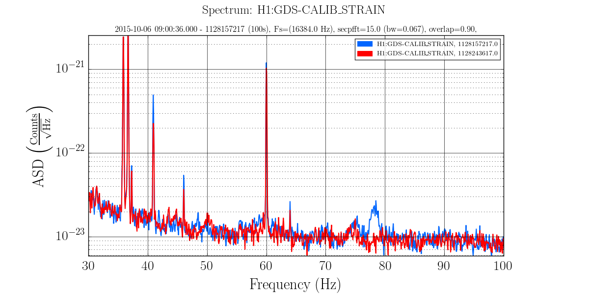
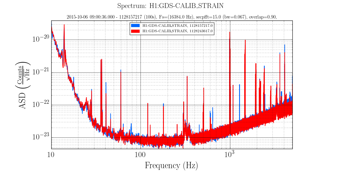
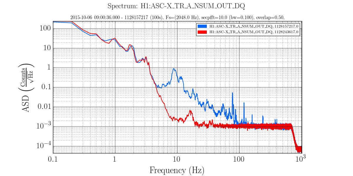
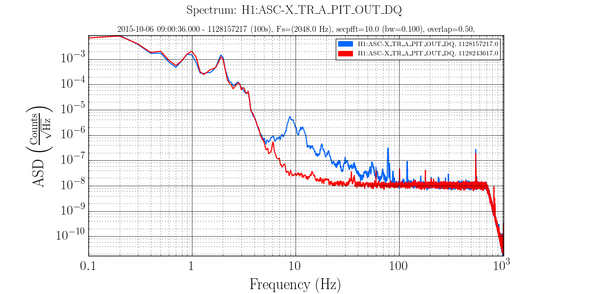
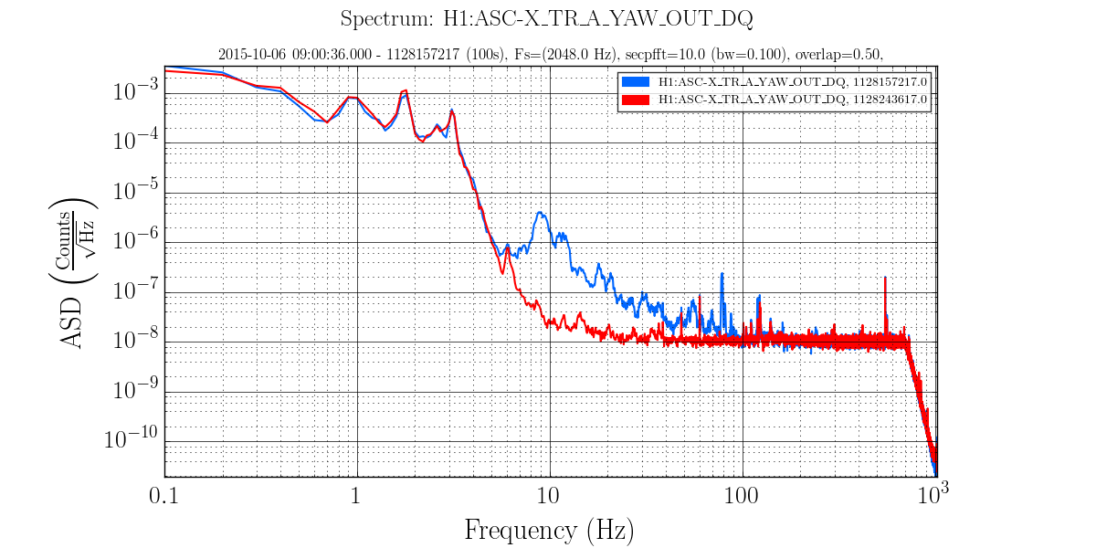
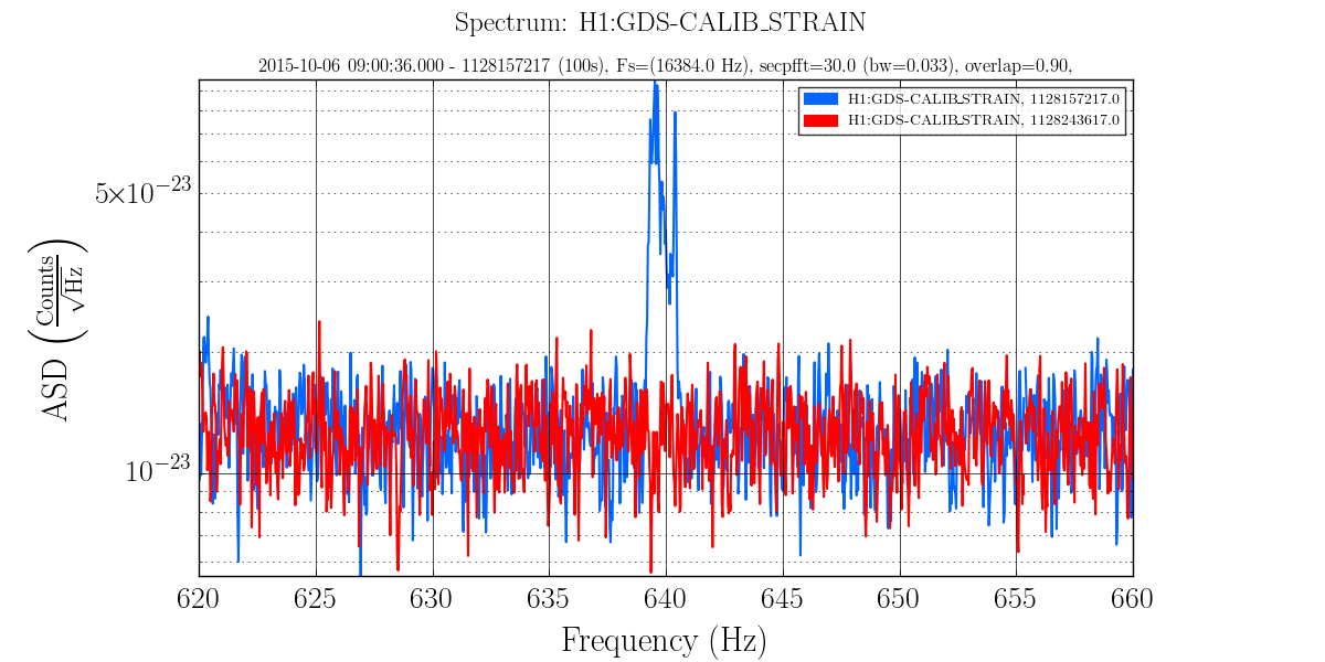
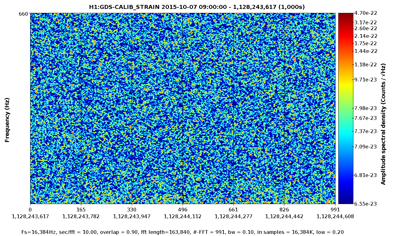
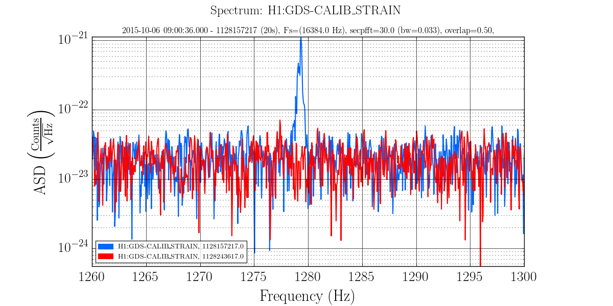
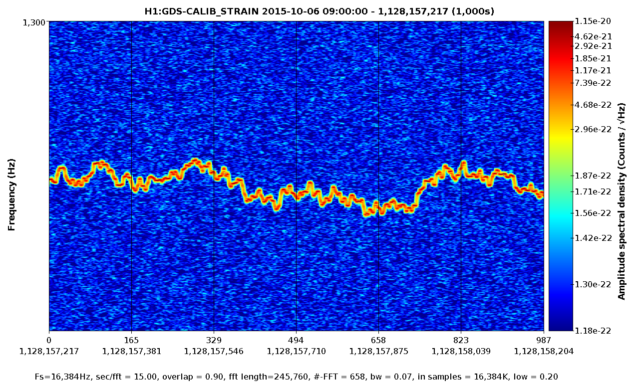
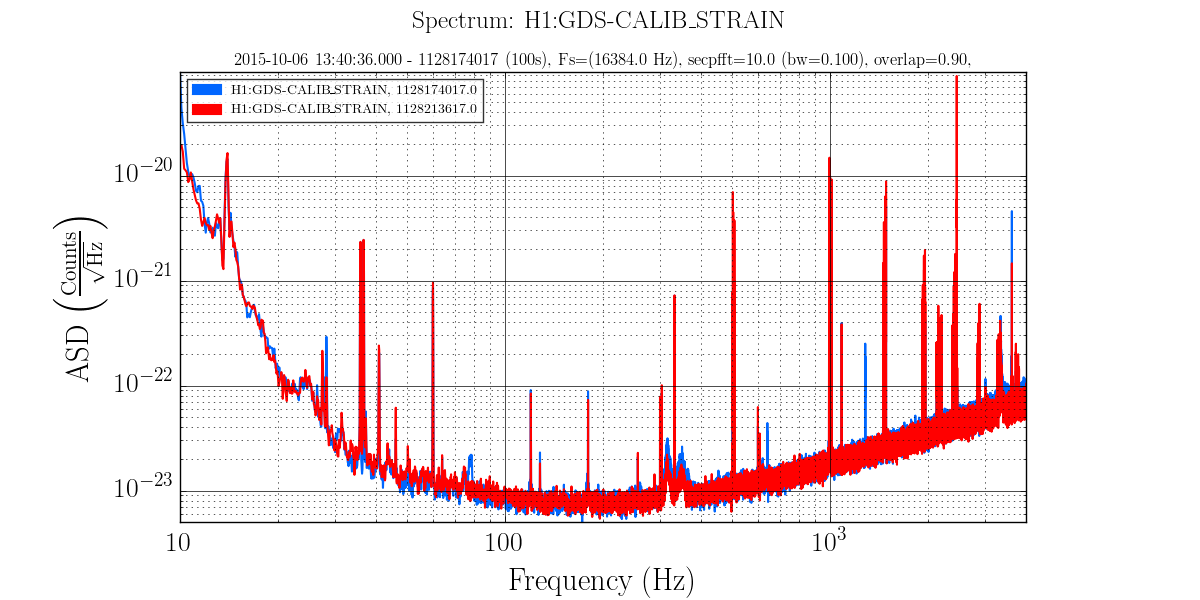
• A major event was the discovery that the EX beam diverter had been open since June when it should have been closed (See this alog and related comments.). As discussed in the alog, several persistent lines in the spectrum disappeared and a number of X and Y arm signals became comparable when this was fixed before the lock on 7 Oct.
• It was noted in the alog that a feature at approximately 0.6 Hz in the Ham3 ISI spectrum disappeared on 7 Oct (alog). This feature has been present at least since 1 July but changed character on 7 Aug and nearly disappeared on 21 Aug.
• Hveto winning channels were H1:SUS-ETMY_L2_WIT_Y_DQ for the long known 60 Hz glitches and ASC-AS_A_RF45_Q_YAW_OUT_DQ which seems to veto the ETMY saturations.
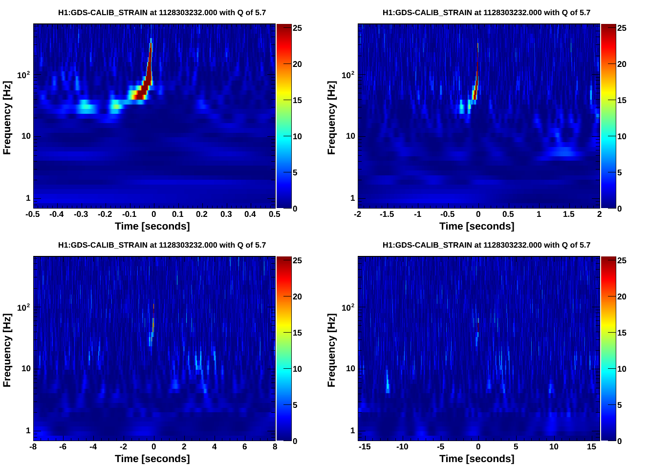
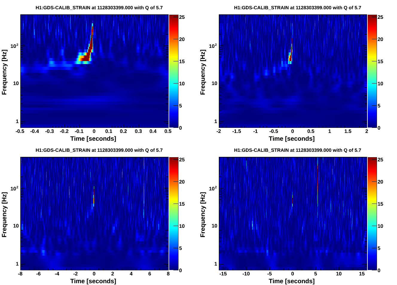
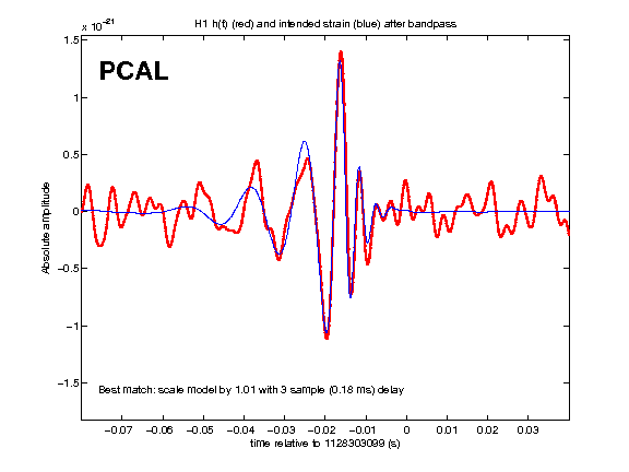
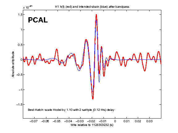
• CBC analyses yielded as the loudest triggers hardware injections and background with new SNR < 8.
More information about this DQ shift may be found here.