JeffreyK, SudarshanK, DarkhanT,
Overview
We made comparison plots of a DARM OLG TF and PCAL to DARM TF measurements taken at LHO with H1DARMmodel_ER8 and H1DARMmodel_O1 (uncorrected and corrected with kappa factors).
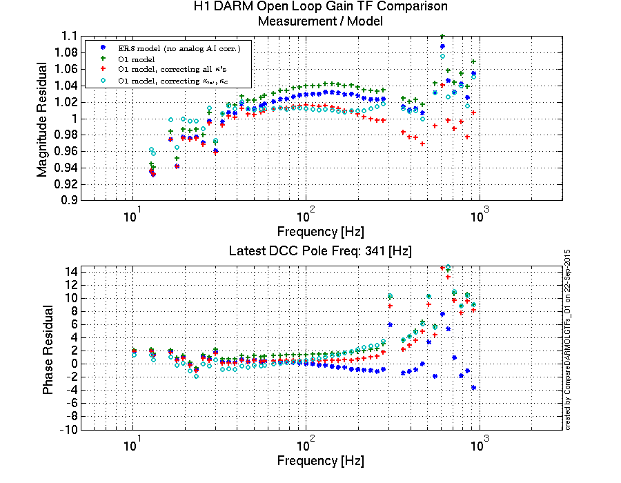
One of the main changes in the DARM model update for O1 compared to ER8 was that in the actuation function for ER8 model we did not account for an analog anti-imaging filter. We included that filter into the O1 model. Adding previously missing analog AI filter into the actuation function model increased the (measurement / model) residual to about 1% in magnitude and to ~6 deg around 500 Hz (~10 deg around 900 Hz). Initally some of the ER8 model parameter estimations (ESD/CD gains) were done to best fit the measurments for actuation function that does not include an analog AI.
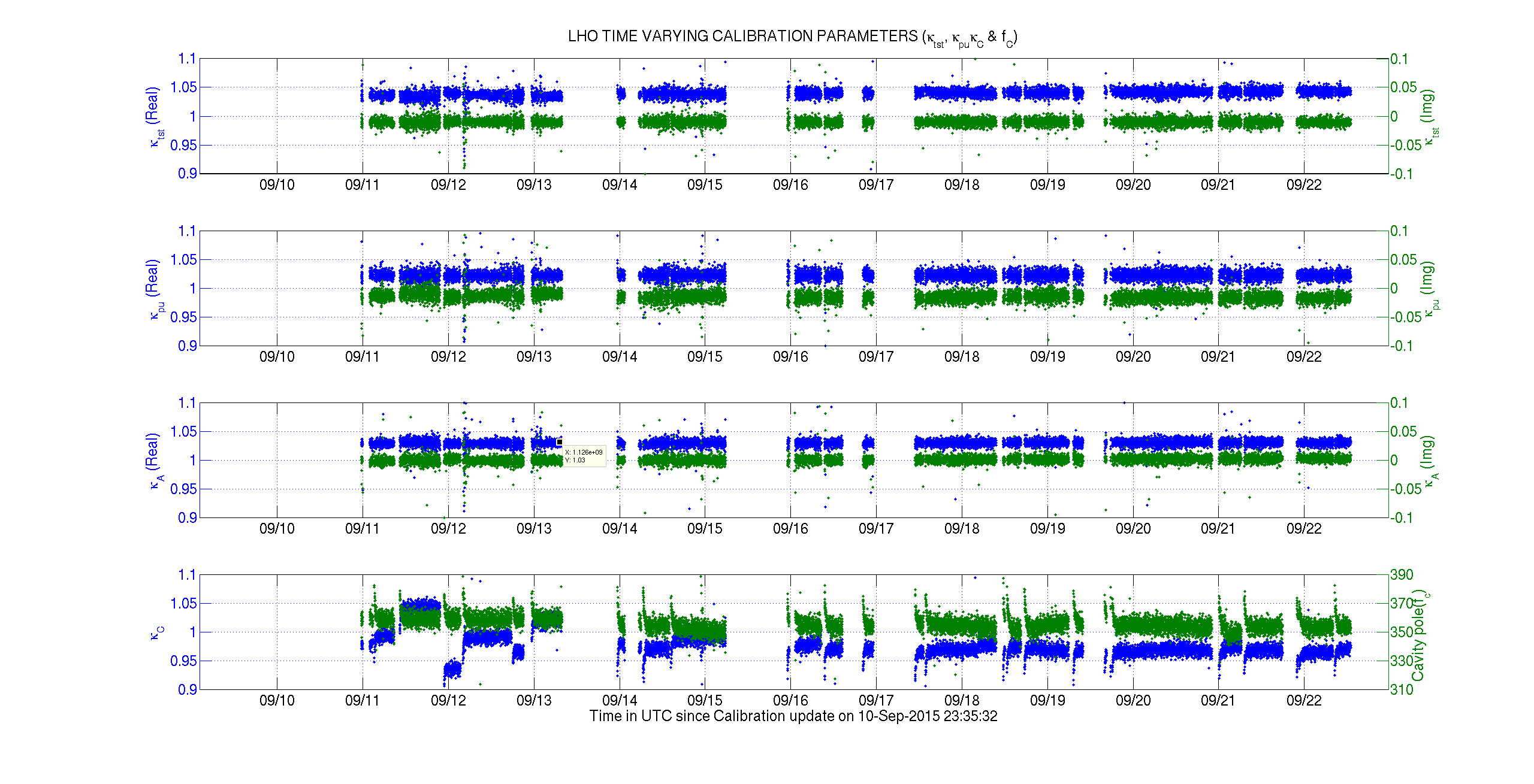
We also took kappas calculated from calibration lines within about 20 minutes from DARM OLG TF measurement and plotted DARM model for O1 corrected with kappas in two different ways against the measurement to see how kappa corrections will take care of systematics in the model. At this point we don't have comparison results of the DARM OLG TF and PCAL2DARM TF measurements and kappa estimations to make a distinct statement. For this particular measurement from Sep 10, the DARM model that was corrected with κtst and κC produced smaller DARM OLG TF residual and actuation function residual compared to uncorrected model, but the sensing function residual was did not improve by the correction (see attached pdf's for actuation and sensing residuals).
Details
Some of the known issues / systematics in our DARM OLG TF model include:
- Not all of the sign flips in ESD (due-to linearization, direction of the applied force) and PUM were explicitly specified in the model parameters (for ESD sign flips see LHO alog 21739), also the location of a sign flip in the loop that is not part of A, C and D was not identified correctly in the beginning of ER8 (for correct location of this "-1" see LHO alog 21601). These issues were fixed in Matlab parameter file and DARM model for O1. Following aspects are affected by these issues:
- inverse actuation filters need to accout for an extra -1 sign (was fixed, see LHO alog 21703);
- CAL-CS reproduction should have a sign that's opposite from DARM output matrix (at LHO we had this correct, but it needed to be fixed at LLO).
- Shivaraj found that DAQ downsampling from 16 kHz to 512 Hz has frequency dependent phase roll-off that accounted for earlier unexplained ~44 degrees of phase discrepancy between the xtst excitation and DARM_ERR readout measurement vs. model.
This issue affects EP1 value that's written into Epics record and used for estimation of DARM time-dependent parameters (T1500377). At LHO in the DARM model for ER8 we manually rotated phase of EP1 to +44.4 degrees to account for this discrepancy; we modified both the paramter file and the DARM model script to account for the DAQ downsampling filter TF calculated at the xtst line frequency.
- JoeB found that an analog anti-imaging filter was not included into the DARM model for ER8 at both LHO and LLO, both sites started with H1DARMmodel_ER8.m script in which we missed to add this filter. On Monday, Sep 21, this issue was fixed in both LLO and LHO DARM models. The issue affects following aspects:
- residuals of actuation function and total DARM OLG TF (systemaic error);
- EP1-9 that are used for estimation of DARM temporal variations.
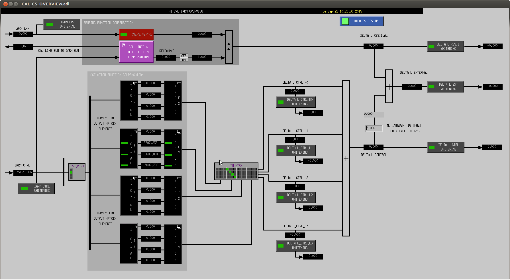
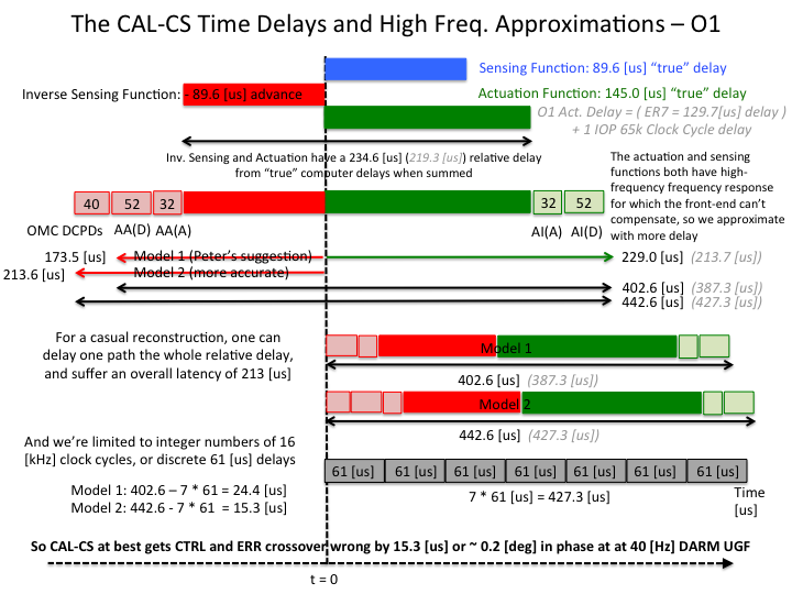
- We had an extra IOP cycle delay added into "par.t.actuation", which was not present in the parameter file and was not used to generate DARM model.
This variable might have been used in GDS calibration, we need to verify with MaddieW to make sure that this extra time delay is not included into GDS code.
- Both sensing and actuation residuals in the DARM model for O1 model extra delay (time-advance). This might be caused by overcounting time-delays or incorrect estimation of some other parameters.
One of the possible sources of systematic error in the sensing function model is using a single-pole TF to approximate IFO response.
Some of the parameters of the actuation functions were estimated without taking into account an analog AI filter (one of the issues listed above). We need to revisit ER8/O1 actuation function analysis results.
A comparison script, an updated DARM model script and DARM paramter files were committed calibration SVN:
CalSVN/aligocalibration/trunk/Runs/O1/H1/Scripts/DARMOLGTFs/
Plots were committed to:
CalSVN/aligocalibration/trunk/Runs/O1/H1/Results/DARMOLGTFs/
P.S. I'll add references later.

Maddie has confirmed that she has used the matlab model parameter par.t.actuation to inform the high-frequency and time-delay corrections to the output of the CAL-CS pipeline.

This confirms that there is a systematic error in the output of the GDS pipeline output at both observatories -- an extra IOP (65 [kHz]) clock cycle, 15 [us] delay on the actuation path, which results in a ~0.5 [deg] phase mismatch between the reconstructed and true actuation and sensing paths at 100 [Hz]. This is small effect, but given our dwindling person-power, and continued pressure to have been done yesterday, we will not quantitatively assess the impact this has on systematic errors. We will instead, merely update the GDS pipeline to use the correct actuation delay (hopefully next Tuesday), and use that as our stopping point for when we stop re-calibrating prior data.