christopher.biwer@LIGO.ORG - posted 18:58, Monday 21 September 2015 - last comment - 06:46, Friday 25 September 2015(21759)
CBC hardware injection test
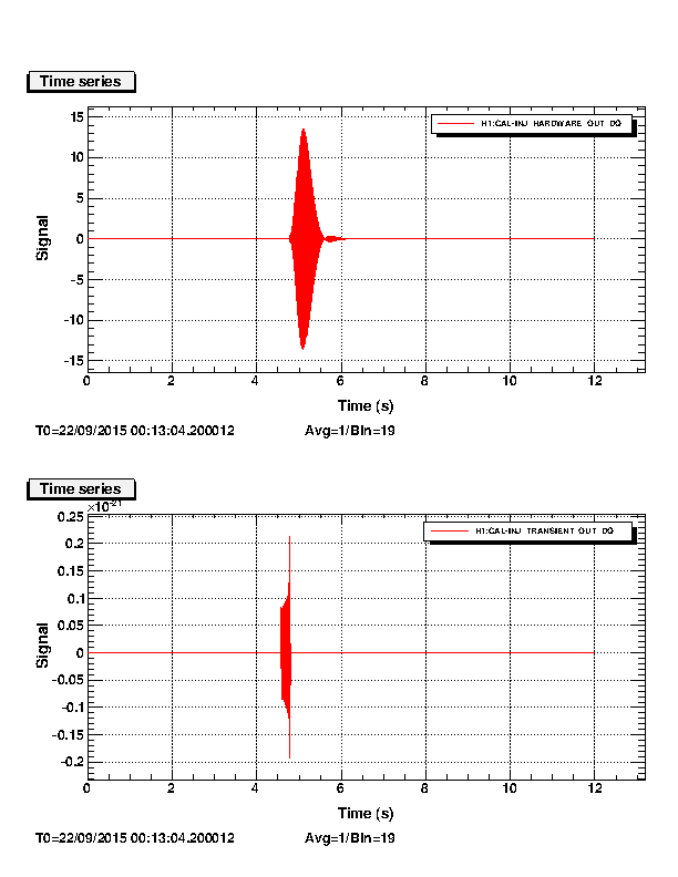
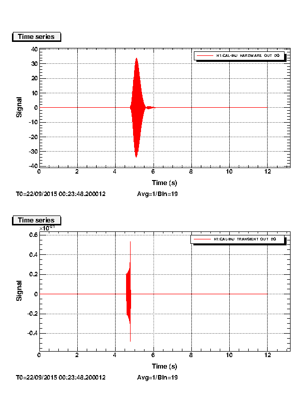
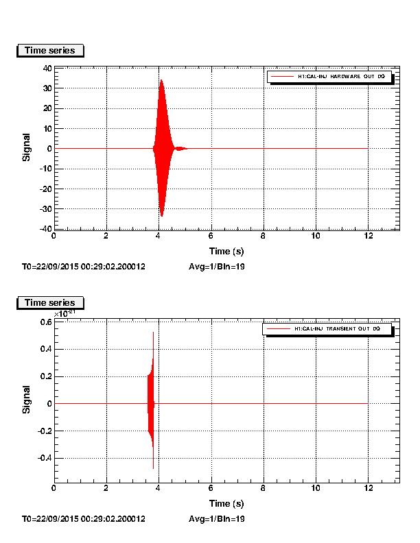
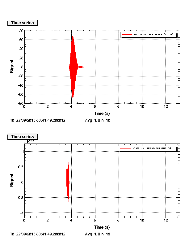
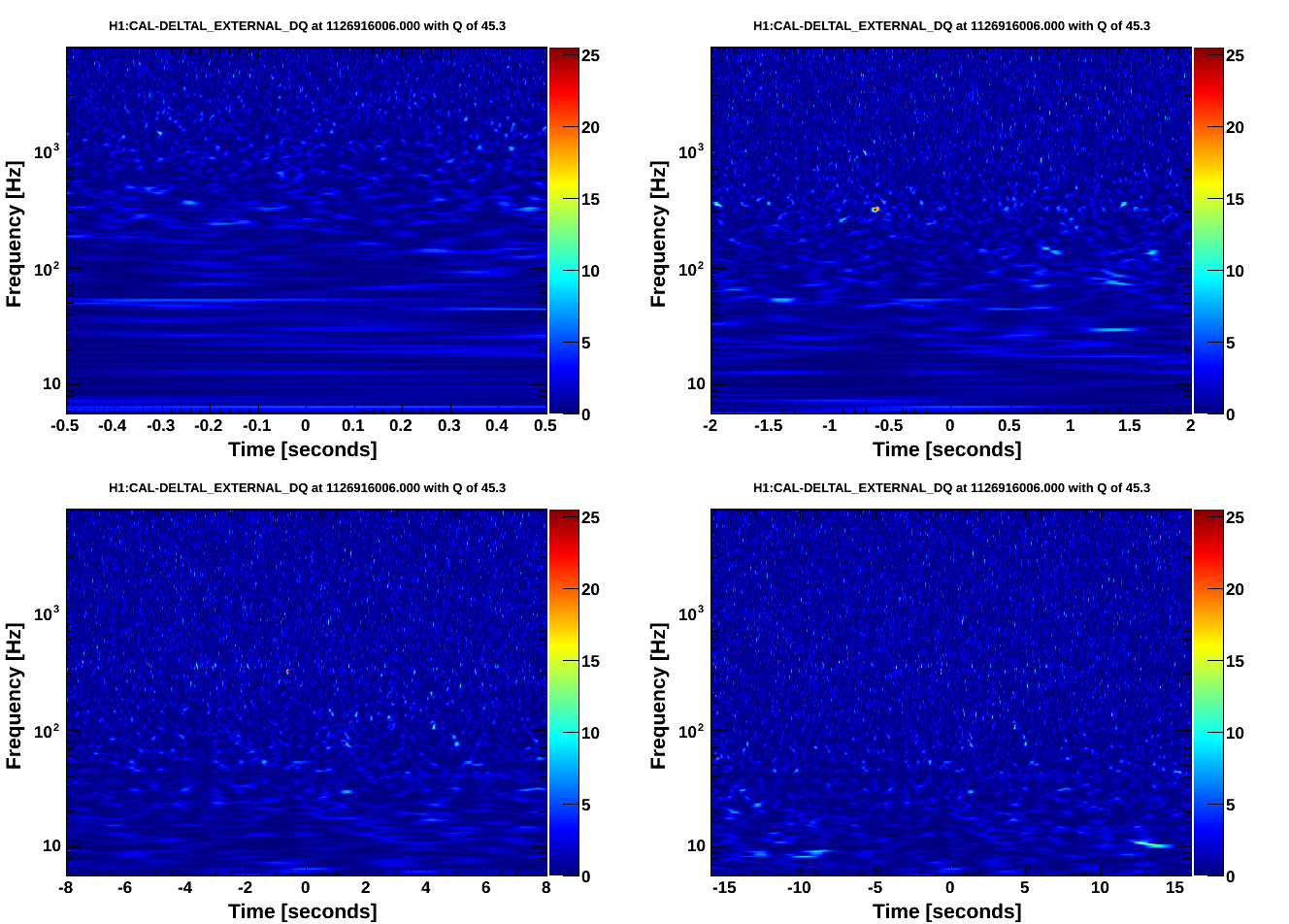
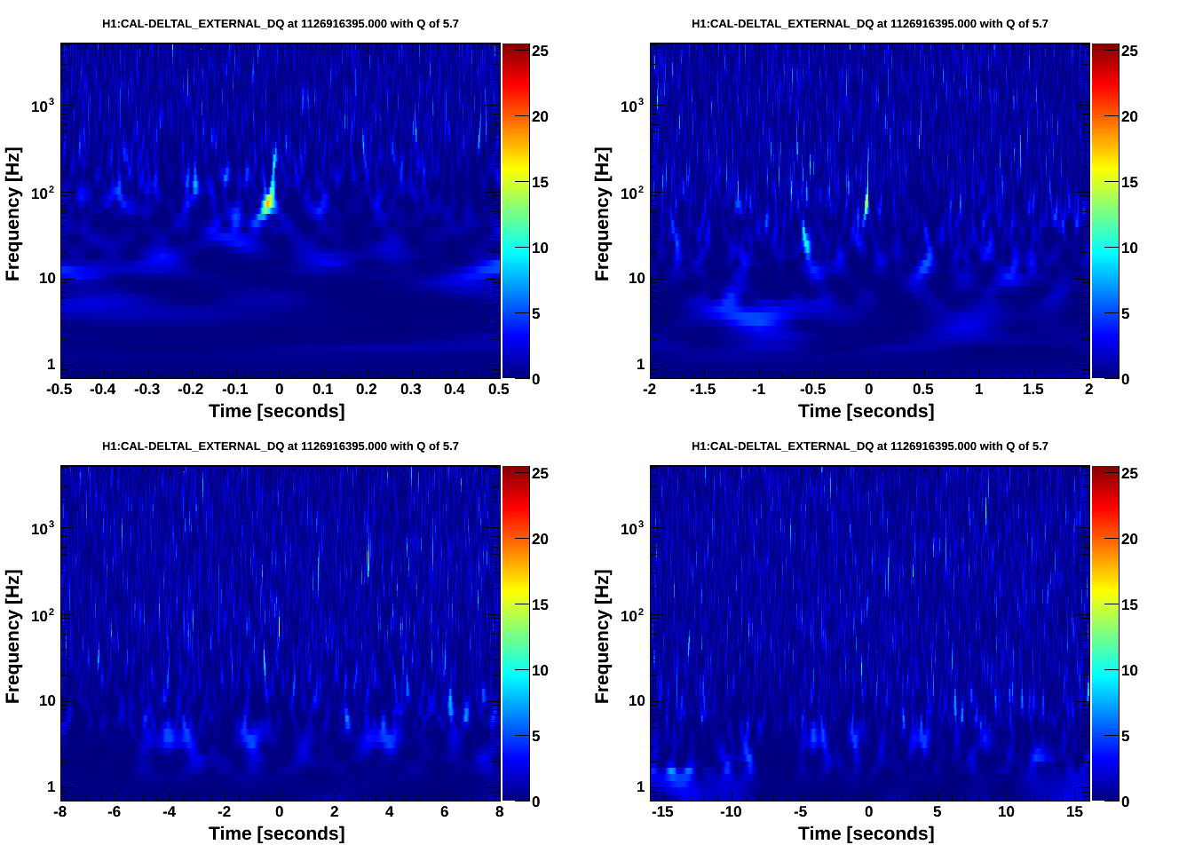
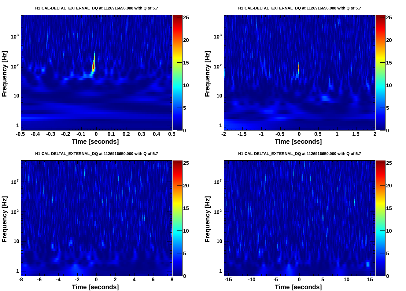
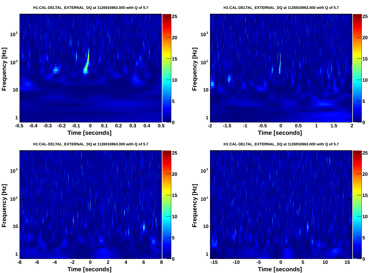
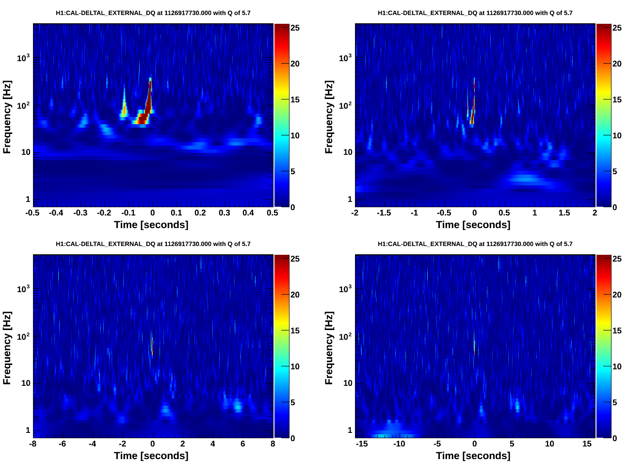
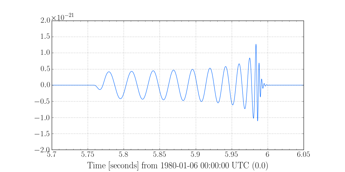
Chris B., Jeff K.

We performed a series of single-IFO hardware injections at H1 as a test. The intent mode button was off at the time.

All injections were the same waveform from aLog 21744.

tinj was not used to do the injections. The command line used to do the injections was:

awgstream H1:CAL-INJ_TRANSIENT_EXC 16384 H1-HWINJ_CBC-1126257410-12.txt 0.2 -d -d
awgstream H1:CAL-INJ_TRANSIENT_EXC 16384 H1-HWINJ_CBC-1126257410-12.txt 0.5 -d -d >> log.txt
awgstream H1:CAL-INJ_TRANSIENT_EXC 16384 H1-HWINJ_CBC-1126257410-12.txt 0.5 -d -d >> log.txt
awgstream H1:CAL-INJ_TRANSIENT_EXC 16384 H1-HWINJ_CBC-1126257410-12.txt 0.5 -d -d >> log.txt
awgstream H1:CAL-INJ_TRANSIENT_EXC 16384 H1-HWINJ_CBC-1126257410-12.txt 1.0 -d -d >> log.txt

I've attached the log (log.txt) which contains the standard output from running awgstream.

Taken from the awgstream log the corresponding times are approximates of the injection time:

1126916005.002499000
1126916394.002471000
1126916649.002147000
1126916962.002220000
1126917729.002499000

The expected SNR the waveform is ~18. The scale factors applied by awgstream should change the SNR by a factor of 0.2 and 0.5 when used.

I've attached timeseries of the INJ-CAL_HARDWARE and INJ-CAL_TRANSIENT. The injections did not reach the 200 counts limit of the INJ_HARDWARE filterbank that we saw in the past.

Watching the live noise curve in the control room we did not notice any strong indication of ETMY saturation which usually manifests itself as a rise in the bucket of the noise curve. But this needs followup.

I've attached omegascans of the injections.
Images attached to this report

Non-image files attached to this report

Comments related to this report
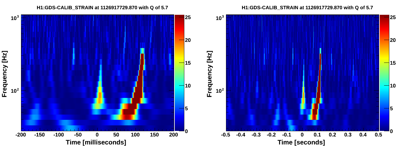
It looks like there's a pre-injection glitch in the last spectrogram. Is that understood?
There were no ESD DAC overflows due to any of the injections. The only such overflow was at 1126916343, which was between injections.

The glitch before the last injection is not understood. It does not correspond to the start of the waveform, which is at GPS time ___29.75. The glitch is at ___29.87 (see attached scan), and I can't find what feature in the waveform it might correspond to. It may be some feature in the inverse actuation filter.

We should repeat this hardware injection to see if the glitch happens again. Subsequent injections should be done with a lower frequency of 15 Hz (this was 30 Hz), to make sure there are no startup effects. This will only make the injection about 3 seconds longer.

In the above, I'm assuming that the hardware injection is always synchronized to the GPS second, so that features in the strain file correspond exactly to what is injected, with just an integer offset. I confirmed that by looking at the injection channel, but someone should correct me if the injection code ever applies non-integer offsets.
Images attached to this comment
If you run awgstream without specifying a start time, it chooses a start time on an exact integer GPS second. (On the other hand, if you DO specify a start time, you can give it a non-integer GPS time and it will start the injection on the closest 16384 Hz sample to that time.)
Note that these CBC injections were recorded by ODC as Burst injections (e.g., see https://ldas-jobs.ligo-wa.caltech.edu/~detchar/summary/day/20150922/plots/H1-ALL_893A96_ODC-1126915217-86400.png) because the CAL-INJ_TINJ_TYPE channel was left at its previous setting, evidently equal to 2.
I completed LALInference followup of these events. linked from https://www.lsc-group.phys.uwm.edu/ligovirgo/cbcnote/aLIGOaVirgo/150827092943PEO1%20parameter%20estimation%20procedure#Hardware_Injections

