J. Kissel, D. Tuyenbayev
Although the jury is still out as to what accuracy we need for the start of O1, I've pushed forward with the plan to design an inverse actuation filter that removes the notches from the test mass stage of actuation, as discussed yesterday (LHO aLOG 21379). In doing so, I've plotted the total DARM actuation function for the first time since (a) we've an updated knowledge each stages' the actuation strength (LHO aLOG 21280), and (b) since the hierarchy filters were changed to reduce the impact of the wide-band impact of PUM violin mode resonances (LHO aLOG 20143).
Regrettably, just like in ER7 (see pg 7 of G1500750), I've discovered that the PUM/L2 interaction with the TST/L3 stage is still very ugly, if not worse than it was. This means that even after taking out the notches in the TST/L3 stage and softening the Q of the TST/L3, 950 [Hz] L3 elliptic filter, there remains very complicated, 30%, 15 [deg] wiggles in the 100 [Hz] to 1000 [Hz] band that would require a great deal of poles and zeros to get correct.
I've found poles and zeros that could be used for a first cut filter, but it really does not do the full actuation function any justice, and is not worth installing. Matt Evans has suggested that he will give it a go tomorrow, but I really think this accelerates the need to inject hardware injections in a different place (the two options being PCAL and further upstream in the SUS actuation chain -- both of which have no notches or elliptic filters or anything complicated to invert). Either that, or we do an honest job cleaning up and rolling off the PUM with a sensible design, which means a significant change to the calibration and impact of the robustness of the IFO operation. Yes, it's just updating digital filters in the front end, but it would be a day or so of model parameter set development, coupled with verification against an open loop gain measurement, and testing whether the IFO was still stable. Kiwamu, Peter, Rick, and I are leaning towards the PCAL option, but we don't yet know what impact this will have on the hardware injection software infrastructure.
As usual, Stay tuned.
#NoSleepTilO1
The full story
--------------
Each page of the first pdf attachment walks you through the story of how I've attempted to go about this.
Just like before the H1 Mini-run and ER7, I've gone into the creation of this filter assuming that below the ~30 [Hz] PUM / TST cross-over frequency the PUM is the PUM stage, and above the TST is the TST stage. As such, I think "I should be able to create a simple set of poles and zeroes that roughly rise the shape of f^2, that I can roll off at high frequency, that may have a few poles and zeroes worth of complication. Certaintly something I can fit into one filter module of 10 second-order-sections. This way I don't have to deal with complicated, often buggy, fitting functions like vectfit or liso, nor with matlab-to-foton filter loading functions that are prone to errors / mistakes like autoquack. Plus I'll truely understand what I'm installing, and I can keep track of the systematic error all along the way."
As such, I started the project as planned: take out the notches from the L3 stage, and reduce the Q of the elliptic filter.
Pg 1 shows the progression as I reduce the complexity of the TST / L3 stage actuation authority. Blue is the full L3 actuation function, as taken directly from the canonical DARM model LHO aLOG 21386. Green is that same model, with the notches removed. Red is the same model, notches removed, and with the Q of the elliptic reduced from essentially infinity to 30.
Pg 2 shows the detail of the tailoring of the elliptic filter.
Great! This'll be nice and easy to invert.
So, I shoved the newly modified L3 / TST stage into the entire actuation function -- and I see a whole bunch of wiggles between 100 and 1000 [Hz] that are just not a part of the L3 / TST actuation (as seen on pg 1).
After quintuple checking for bugs, I plotted the decomposition of the total actuation function into all stages. This is pg 4. One can immediately see from this that there are interactions between the PUM and TST stage well-above the PUM / TST cross-over frequency. YUCK.
After digging around a little bit, I take a look at the filters that have been installed when the control authority was "reduced" in LHO aLOG 20143. I see that not only was the PUM *not* rolled off better, but the notches and elliptic filters that were put in place *instead* of just softly rolling off the stage better are just rediculous. Bode plots of the PUM notch filters and elliptic filters are shown in the second attachment for proof.
Finally, just so I could demonstrate how a simple, 10-pole, 10-zero fit just would in no way be able to reproduce this actuation function, I put together such a function and caluculated the residuals. Pg 5 and 6 (back to the first attachment) show these residuals.
----------
The analysis script that generated these plots and the filter are here:
/ligo/svncommon/CalSVN/aligocalibration/trunk/Runs/ER8/H1/Scripts/InvActuation/generate_invactuation_filter_ER8.m
The model and parameter file to generate the full actuation function live here:
/ligo/svncommon/CalSVN/aligocalibration/trunk/Runs/ER8/H1/Scripts/DARMOLGTFs/
H1DARMOLGTFmodel_ER8.m
H1DARMparams_1125963332.m
The filter file that contains the digital filters in the SUS chain lives here:
/ligo/svncommon/CalSVN/aligocalibration/trunk/Common/H1CalFilterArchive/h1susetmy/H1SUSETMY_1124818267.txt
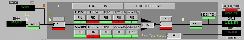
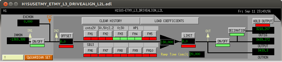
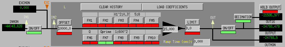
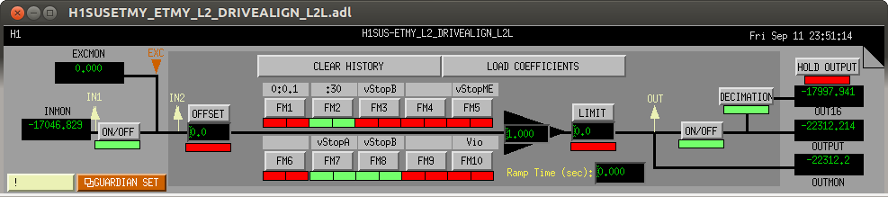
I attach the filter file and screenshots of all relavant filter banks here, for Matt's convenience, if he wants to waste a perfectly good Saturday.


SVNs required for this:
svn co https://svn.ligo.caltech.edu/svn/aligocalibration/trunk/Runs/ER8 CalSVN/aligocalibration/trunk/Runs/ER8svn co https://svn.ligo.caltech.edu/svn/aligocalibration/trunk/Common/H1CalFilterArchive CalSVN/aligocalibration/trunk/Common/H1CalFilterArchive
svn co https://svn.ligo.caltech.edu/svn/aligocalibration/trunk/Runs/S7/Common/MatlabTools CalSVN/aligocalibration/trunk/Runs/S7/Common/MatlabTools
svn co https://svn.ligo.caltech.edu/svn/seismic/Common/MatlabTools SeismicSVN/seismic/Common/MatlabTools
svn co https://redoubt.ligo-wa.caltech.edu/svn/sus/trunk/Common/SusModelTags/Matlab SusSVN/sus/trunk/Common/SusModelTags/Matlab
All of which results in an ETMY actuation function, saved in the attached .mat file (and shown in the image). In the attached image, I have removed the 1/f^2 slope to reveal the bumps and wiggles of the TF that needs to be inverted.
A fit to the actuation function is attached, along with images of the fit and the residual. Mostly, the fit is within 10% and 5dg from 10Hz to 1kHz. The pole and zero Qs are not very large, so the inverse should be workable.