Jenne, Nergis, Stefan
We hooked up monitoring points for measuring the 9MHz and 45MHz RIN going into the interferometer.
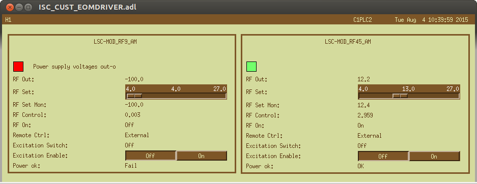
Here is the rig:
9MHz:
- We inserted a 10dB coupler into the 9MHz cable feeding the EOM. This dropped the drive signal from 4.7Vpkk to 4.5Vpkk - small enough the interferometer didn't care.
- It's output we directed into a two-way splitter, and fed both signals into a level 1 mixer.
- The output was low-passed through a 10MHz low pass.
- This gave us a DC level of 0.195V, and a noise of ~4.9nV/rtHz, resulting into a RIN of 2.5e-8.
- We hooked it up to an SR560 (Gain=1e4, AC coupled, band-passed with poles at 300Hz and 30kHz), and stuck it into LSC-EXTRA_AI_1 (IOP-LSC0_MADC2_TP_CH8)
- the ADC gain is 16384cts/10V
45MHz:
- We used the two remaining spare spigots of the 45MHz distribution rack, and mixed them in a level 3 mixer.
- Low-passed at 15MHz, we got a DC level of 0.57V, and a noise level of 120nV/rtHz...
- ... resulting in an outrageous RIN of 2e-7/rtHZ
- Again into an SR560 (Gain=1e3, AC coupled, band-passed with poles at 300Hz and 30kHz)
- and into LSC-EXTRA_AI_2 (IOP-LSC0_MADC2_TP_CH9)
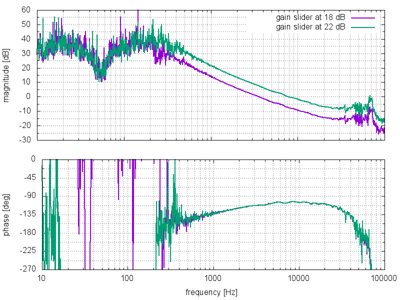
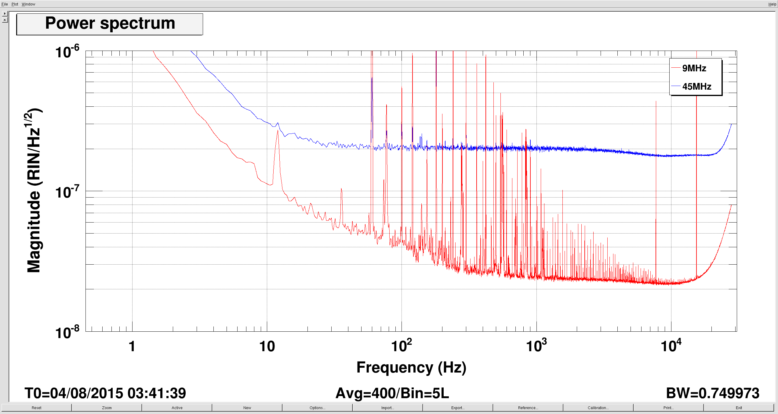
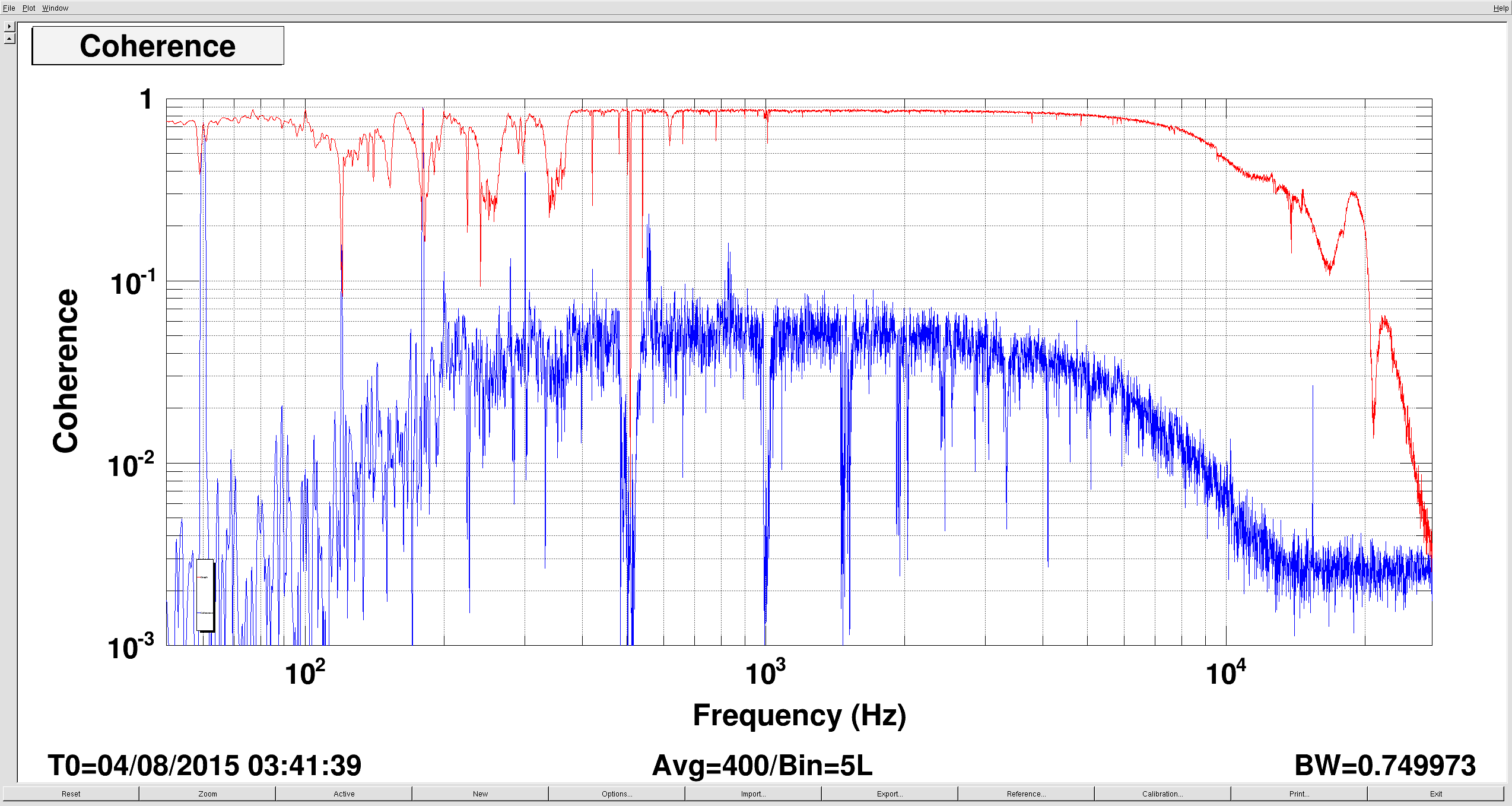
Plot 1 shows the RIN measured through the digital system
Calibration: LSC-EXTRA_AI_1 (IOP-LSC0_MADC2_TP_CH8): Gain=9.39e-5; p= 1, 728.178 65532 ; z= 300, 30000, 10062, 4973.6 9356.4, 33157, 426840 (dtt notation)
Calibration: LSC-EXTRA_AI_2 (IOP-LSC0_MADC2_TP_CH9): Gain=3.21e-4; p= 1, 728.178 65532 ; z= 300, 30000, 10062, 4973.6 9356.4, 33157, 426840 (dtt notation)
Note: the AA chasis itself has p= 728.178 65532 ; z= 10062, 4973.6 9356.4, 33157, 426840 (dtt notation)
Next Evan locked the interferometer, and we found a coherence of 0.9 between the 45MHz RIN (IOP-LSC0_MADC2_TP_CH9) and ASC_AS_C (IOP-ASC0_MADC6_TP_CH11) - this was oue best monitor for mystery noise.... BINGO
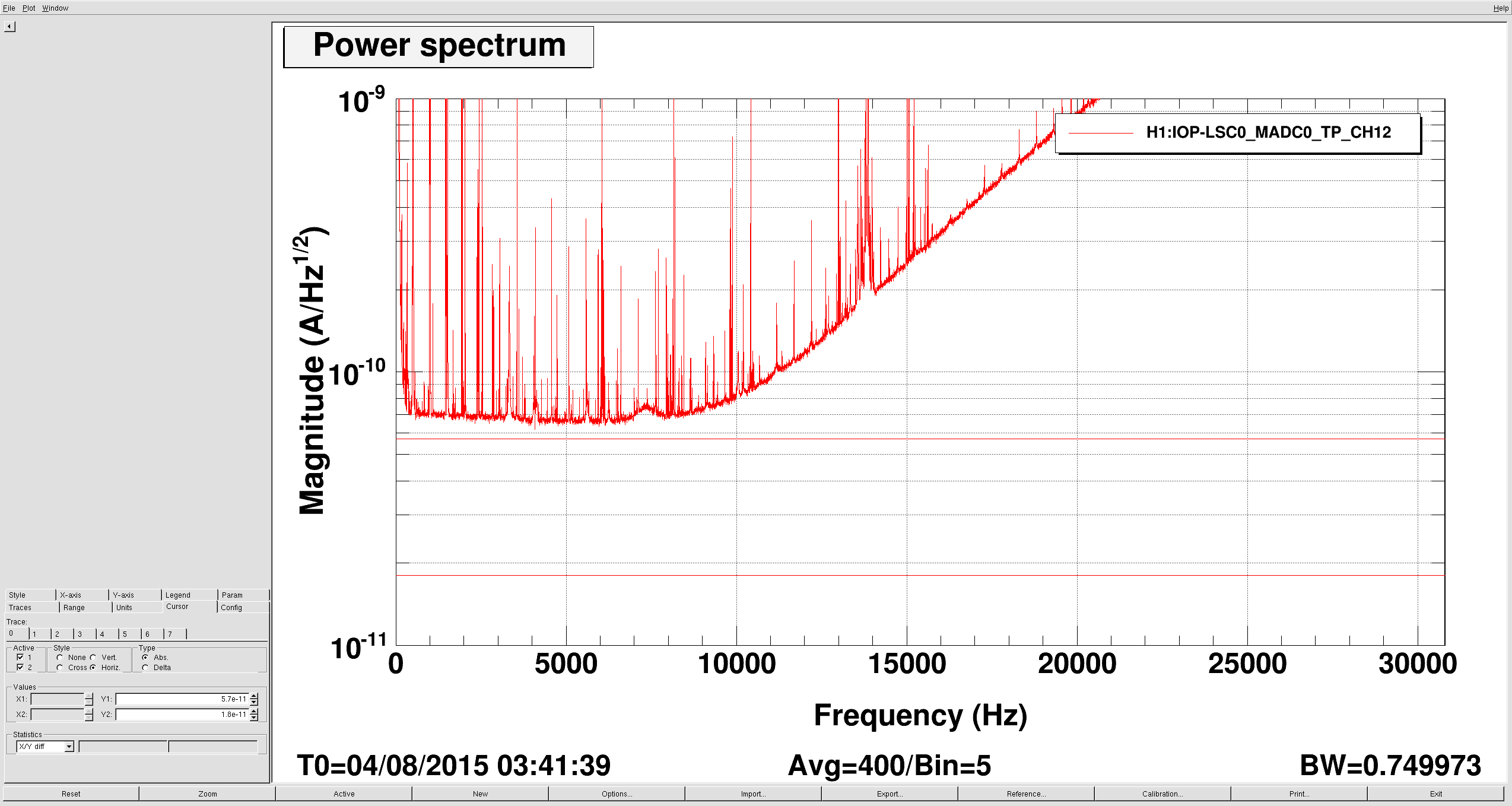
We also calibrated OMC_DCPD_A (IOP-LSC0_MADC0_TP_CH12) in Amps (today the whitening filters were off):
Calibration:Gain=7.726e-7; p= 7.689, 7.689, 728.178 65532 ; z= 78.912, 90.642, 13700, 17800, 10062, 4973.6 9356.4, 33157, 426840 (dtt notation)
The noise level in OMC_DCPD_A was 7e-8mA/rtHz. Shot noise would be 5.7e-8mA/rtHz at 10mA.
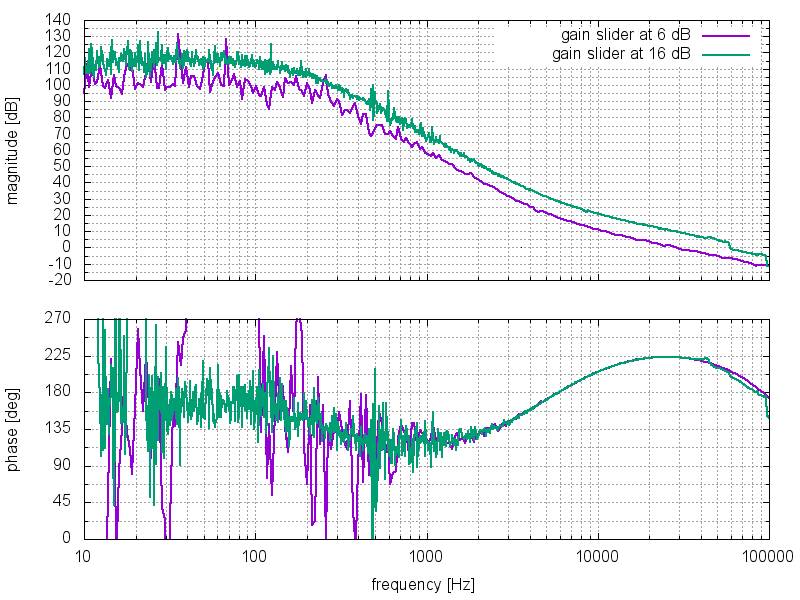
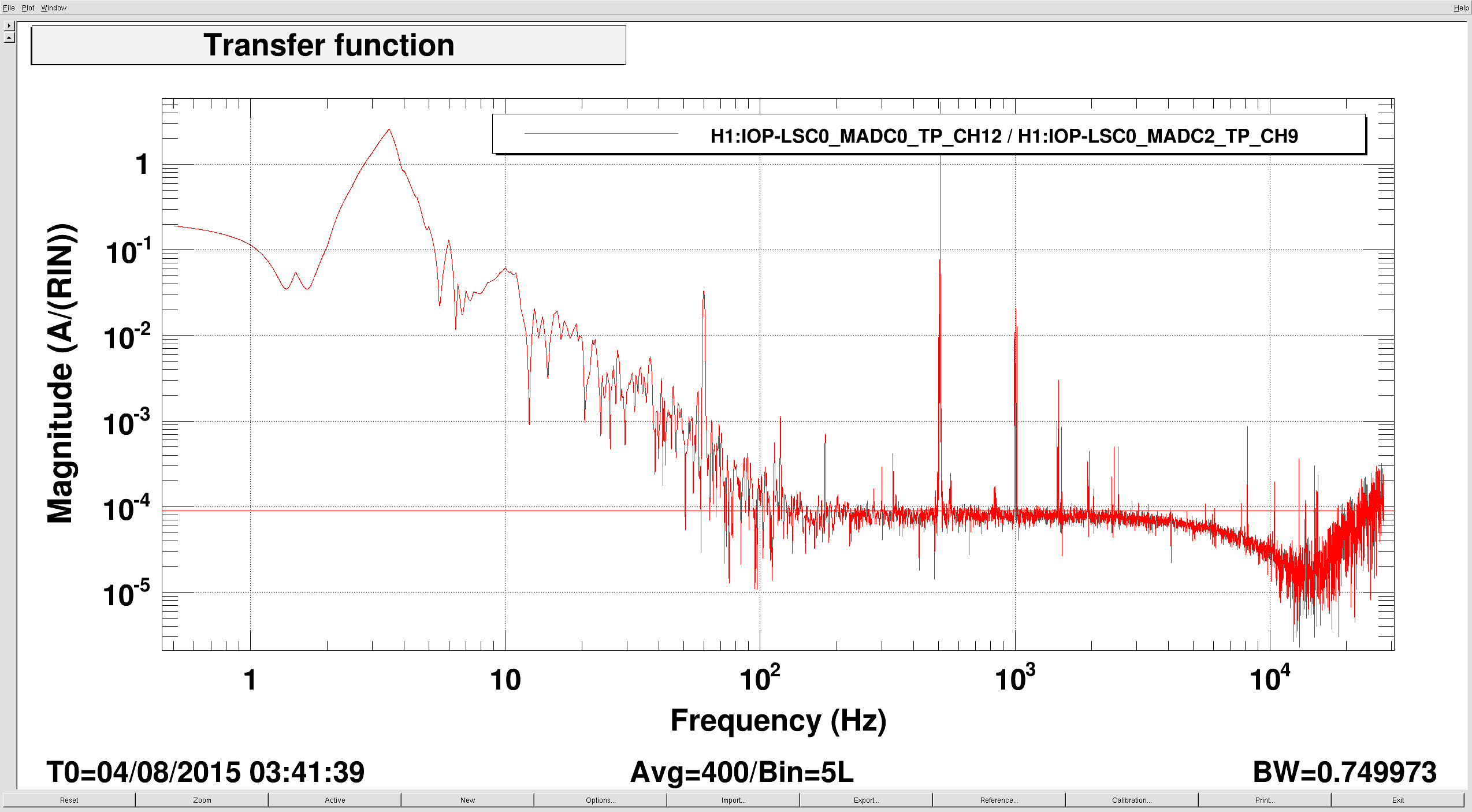
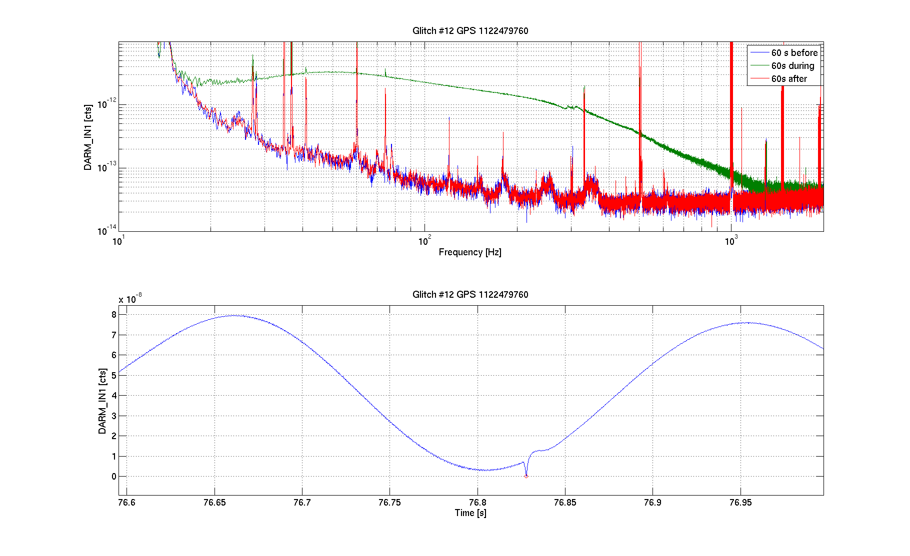
Using the coherence between OMC_DCPD_A and RF45 RIN we estimated the ransfer function to be about 9e-5 A/RIN per photo diode. (Plot2)
This let's us estimate the RF45 RIN contribution: 9e-5 A/RIN * 2e-7RIN/rtHz = 1.8e-8mA/rtHz. Very close to the 1.4mA/rtHz estimated in alog 19856.
We are a bit puzzled by the fact that this doesn't seem enough the explain the full elevated noise in DCPD_A: sqrt(1.8^2 + 5.7^2) = 6.0 < 7 (everything x1e-8mA/rtHz). (Plot3)
Plot 4 shows the coherence (ignore below 300Hz - the interferometer wasn't completely in low noise mode.