Related:
Den's alog 16624
Den's alog 16727
Summary:
Many things are dubious.
-
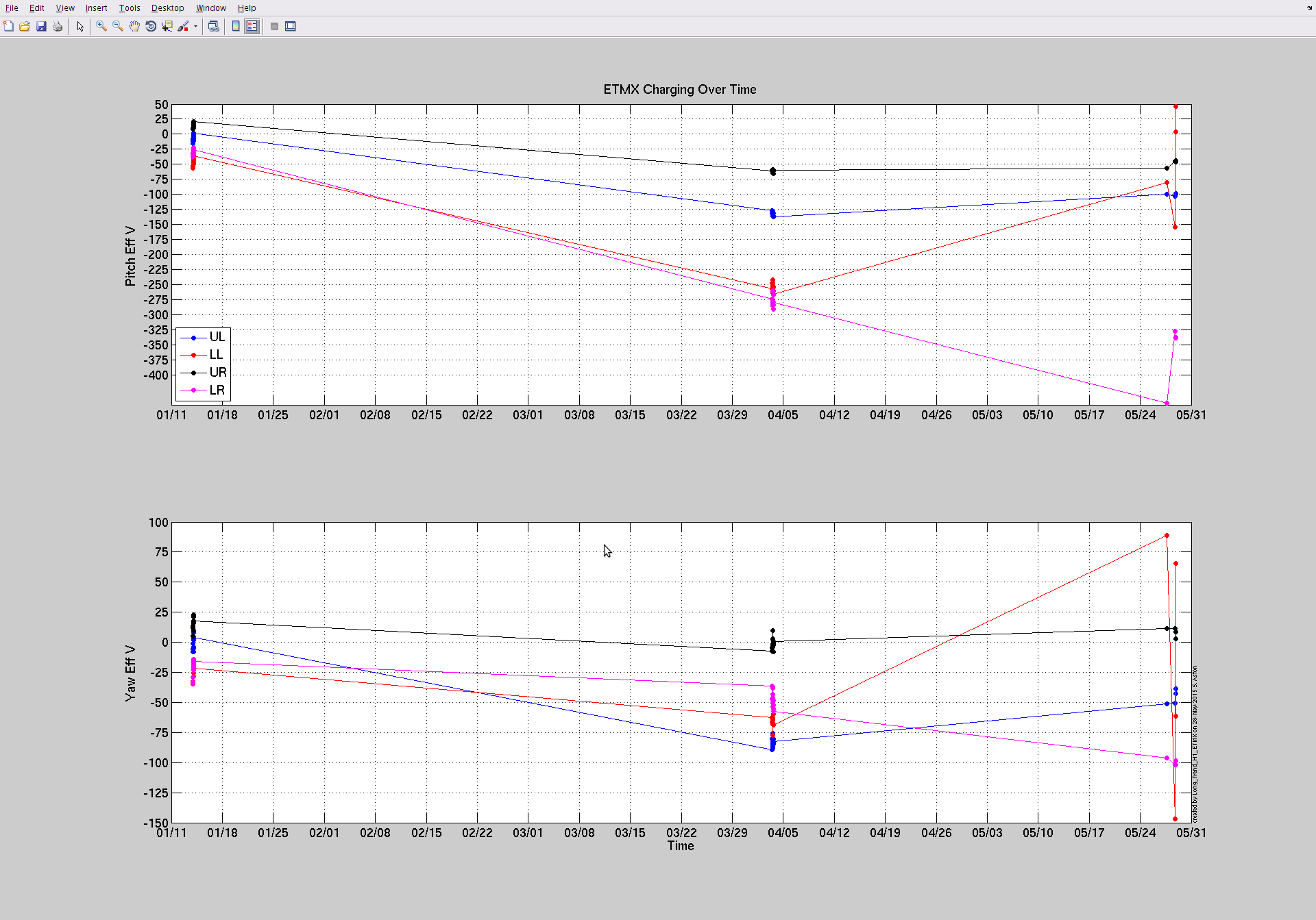
EX LL ESD is broken as the ESD to length response is 3 orders of magnitude smaller than the others. Probably shoddy connection somewhere between the driver and the ESD electrode, as the voltage readback looks normal.
-
It looks as if either the sign of EX ESD output is flipped (positive digital out induces negative voltage) or the sign of EY ESD output is flipped but not both.
-
I'm just assuming that the sign convention for CAL-CS_DARM_EXTERNAL_DQ is length(X)-length(Y), and that it's correct, without any confirmation.
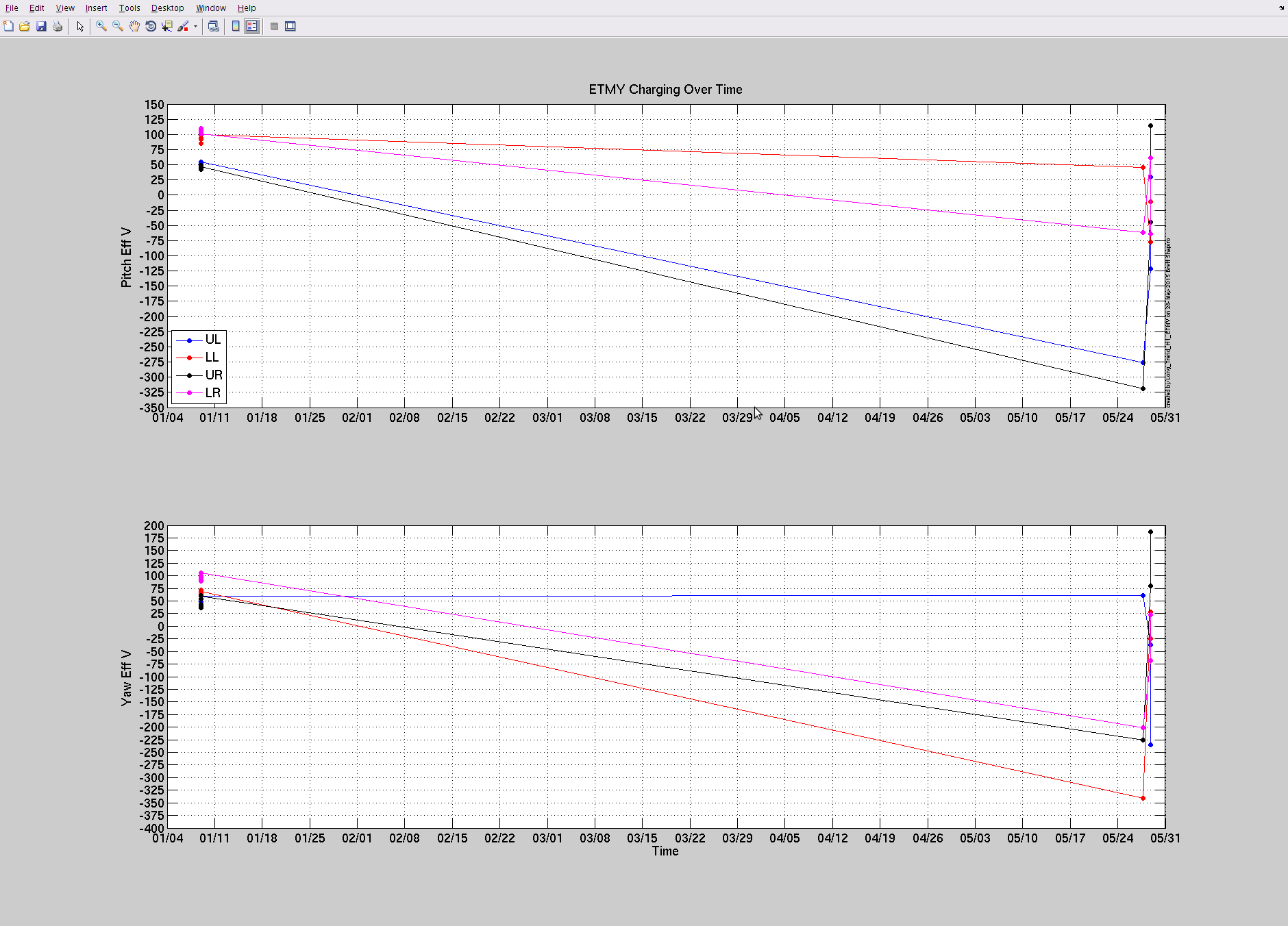
Despite these things, it seems as if the charges on the back are on the same order as reported in Den's alog 16624.
If we assume that the sign of EY ESD is wrong and we still take 1. into account, the charges are calculated as:
|
|
front |
back |
|
X |
4.4nC |
1.1nC |
|
Y |
2.2nC |
1.2nC |
This looks semi-reasonable.
If we assume that the sign of EX ESD is wrong and we still take 1. into account, the charges are:
|
|
front |
back |
|
X |
5.7nC |
-0.9nC |
|
Y |
-6nC |
-0.4nC |
I don't like that the signs are all over the place.
If we assume that everything is correct except that the EX LL is broken (i.e. we ignore the 2. above but take 1. into account), the charges based on are:
|
|
front |
back |
|
X |
4.4nC |
1.1nC |
|
Y |
-6nC |
-0.4nC |
Again the signs are all over the place.
These are based on the same calculation as Den's alog 16624.
I'm assuming that the sign convention of CAL-CS_DARM_EXTERNAL_DQ is length(X)-length(Y) (i.e. positive when X stretches and Y shrinks).
Anyway, no matter how you look at the data, the back surface charges are quite similar to what was reported in Den's alog (except for the signs that don't make much sense for the latter two tables).
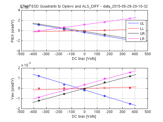
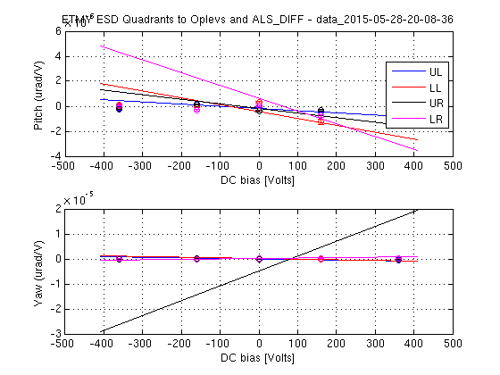
We tried similar measurements as described in Den's alog 16727 but the angle data for X was unusable (no coherence at all). If you're interested in Y data, all measurements were saved in Betsy's template directory.
The gist of the measurements:
-
Lock the IFO in DC using EX ESD for EY injections (or using EY ESD for EX injections). Use a correct-ish CAL-CS configuration.
-
Ring heater upper and lower sections were bundled together and connected to one of GDS DACs via SR560 while the drive ground was connected to the ESD ground.
-
Set the EY ESD bias to zero for EY injections (or EX bias for EX injections).
-
Inject 5 lines (each one corresponding to LL, LR, UL, UR and ring heater), all at around 80Hz, and measure the transfer coefficients from injections to CAL-CS_DARM_EXTERNAL_DQ and IR QPDs on the TMS. CAL_CS thing was dewhitened using the calibration in the dtt template used for the control room FOM.
Differences between EX and EY measurements:
-
Low noise driver, no low pass for EY. This gives a DC gain of 2, and a pole at 152Hz from PI summing node. For EX, high voltage driver with DC gain of 40 and a pole at 2kHz.
-
High power for EY injections. Low power (3W) for EX injections because we needed to disable EX ring heater and I was worried if the PI becomes the problem if the measurement takes too long.
-
In EY a large DC analog offset was observed in all GDS testpoints. To block this, SR560 was set to AC coupling which should have zero effect at 80Hz. (Later it turned out that the offset was already in the digital, so probably it's a digital offset problem but that doesn't change the conclusion either.)
-
No meaningful coherence for the QPDs in EX. Don't know why, maybe we really need high power.
Fishy sign of ESDs (Go to the floor and figure out):
EY ESD length drivealign matrix has a negative DC gain while the corresponding matrix for EX is positive even though the LSC DARM output matrix already takes care of the sign difference necessary for DARM control for EX and EY.
It looks as if either the bias line has a wrong sign for one ETM but not the other, or LL/LR/UL/UR lines have a wrong sign for one ETM but not the other.
Raw-ish data and calculations:
Measured the zero-bias transfer coefficients from ESD segments and the ring heater (top and bottom combined) to the calibrated DARM channel in meters/volts at around 80Hz. After taking the TF of the drivers and the DAC V/cts into account, they are:
|
|
LL [m/V] |
LR [m/V] |
UL [m/V] |
UR [m/V] |
ESD combined [m/V] |
Ring Heater [m/V] |
|
EX |
+1.3E-18 |
+2.2E-15 |
+1.0E-15 |
+5.6E-16 |
+3.8E-15 * 4/3 |
-6.7E-16 |
|
EY |
+5.6E-16 |
+6.5E-16 |
+1.4E-15 |
+1.5E-15 |
+4.1E-15 |
+1.9E-15 |
Positive data is actually about 24 deg (Y arm) or 30 deg (X arm) delayed, while negative data is about 210 deg (X arm) delayed.
EX LL is not working. Coherence is very large, the voltage readback looks OK, but it has 3 orders of magnitude smaller response than the others. EX LL did not change much when the nominal EX ESD bias was put back on.
I multiplied the ESD combined data by 4/3 only for EX to take into account that the EX LL driver is not working.
Force to length transfer function at 80Hz is -1/M/(2*pi*80Hz)^2 = -1E-7[m/N] (negative as the phase is 180 degrees relative to DC).
Also, the above is the TF to DARM, which is supposed to be X length - Y length. In order to move to a sign convention where positive means that the ETM moves closer to ITM, the sign of the X data should be flipped.
Combining these, the above raw-ish data is converted to N/V as:
|
|
LL [N/V] |
LR [N/V] |
UL [N/V] |
UR [N/V] |
ESD combined [N/V] |
Ring Heater [N/V] |
|
EX |
+1.3E-11 |
+2.2E-8 |
+1.0E-8 |
+5.6E-9 |
+3.8E-8 * 4/3 |
-6.7E-9 |
|
EY |
-5.6E-9 |
-6.5E-9 |
-1.4E-8 |
-1.5E-8 |
-4.1E-8 |
-1.9E-8 |
The signs of this table don't really make sense (positive ESD electrode potential should move ETMX and ETMY in the same direction if the charge has the same sign).
Anyway, from here, you solve Den's rough formula:
FRH / VRH = Afront Qfront + Aback Qback
FESD / VESD = Bfront Qfront + Bback Qback
Afront = 1 / 0.20 [1/m] ; Aback = -1 / 0.04 [1/m]
Bfront = 1 / 0.20 [1/m] ; Bback = 1 / 0.04 [1/m]