Sheila, Elli
I moved the ITMs to improve the recycling gain, as well as the PRM. To get from a recylcing gain of just under 36 to 39 I mostly moved ITMY in yaw. This may be a different alignment than what we were using durring ER7, but it seems to be an improvement over the alingments we had yesterday, so we have updated references for now. The green alignment in the X arm did not change, but Elli and I redid the green QPD offsets and camera position for the Y arm. We lost lock and relocked allowing the ASC to engage with the guardian using these new IR QPD offsets, which was fine and brought us to a recycling gain of 39 again. For now the many people who want to do things incompatible with full locking have taken over the IFO.
Old offsets:
sheila.dwyer@opsws3:~/StripTools$ caget H1:ASC-Y_TR_A_PIT_OFFSET H1:ASC-Y_TR_A_YAW_OFFSET H1:ASC-Y_TR_B_PIT_OFFSET H1:ASC-Y_TR_A_PIT_OFFSET
H1:ASC-Y_TR_A_PIT_OFFSET -0.192
H1:ASC-Y_TR_A_YAW_OFFSET -0.365
H1:ASC-Y_TR_B_PIT_OFFSET -0.32
H1:ASC-Y_TR_A_PIT_OFFSET -0.192
sheila.dwyer@opsws3:~/StripTools$ caget H1:ASC-X_TR_A_PIT_OFFSET H1:ASC-X_TR_A_YAW_OFFSET H1:ASC-X_TR_B_PIT_OFFSET H1:ASC-X_TR_B_YAW_OFFSET H1:ASC-X_TR_A_PIT_OFFSET -0.084
H1:ASC-X_TR_A_YAW_OFFSET -0.023
H1:ASC-X_TR_B_PIT_OFFSET -0.212
H1:ASC-X_TR_B_YAW_OFFSET 0.006
sheila.dwyer@opsws3:~/StripTools$ caget H1:ASC-POP_A_PIT_OFFSET H1:ASC-POP_A_YAW_OFFSET
H1:ASC-POP_A_PIT_OFFSET 0.4
H1:ASC-POP_A_YAW_OFFSET 0.26
sheila.dwyer@opsws3:~/StripTools$ caget H1:ASC-POP_A_PIT_OFFSET H1:ASC-POP_A_YAW_OFFSET
H1:ASC-POP_A_PIT_OFFSET 0.4
H1:ASC-POP_A_YAW_OFFSET 0.26
Green references:
H1:ALS-Y_QPD_B_YAW_OFFSET 0.2
H1:ALS-Y_QPD_A_YAW_OFFSET -0.2
H1:ALS-Y_CAM_ITM_PIT_OFS 300
H1:ALS-Y_CAM_ITM_YAW_OFS 428.5
New offsets:
sheila.dwyer@opsws3:~/StripTools$ caget H1:ASC-Y_TR_A_PIT_OFFSET H1:ASC-Y_TR_A_YAW_OFFSET H1:ASC-Y_TR_B_PIT_OFFSET H1:ASC-Y_TR_A_PIT_OFFSET
H1:ASC-Y_TR_A_PIT_OFFSET -0.118
H1:ASC-Y_TR_A_YAW_OFFSET -0.242
H1:ASC-Y_TR_B_PIT_OFFSET -0.369
H1:ASC-Y_TR_A_PIT_OFFSET -0.118
sheila.dwyer@opsws3:~/StripTools$ caget H1:ASC-Y_TR_A_PIT_OFFSET H1:ASC-Y_TR_A_YAW_OFFSET H1:ASC-Y_TR_B_PIT_OFFSET H1:ASC-Y_TR_A_PIT_OFFSET
H1:ASC-Y_TR_A_PIT_OFFSET -0.118
H1:ASC-Y_TR_A_YAW_OFFSET -0.242
H1:ASC-Y_TR_B_PIT_OFFSET -0.369
H1:ASC-Y_TR_A_PIT_OFFSET -0.118
sheila.dwyer@opsws3:~/StripTools$ caget H1:ASC-X_TR_A_PIT_OFFSET H1:ASC-X_TR_A_YAW_OFFSET H1:ASC-X_TR_B_PIT_OFFSET H1:ASC-X_TR_B_YAW_OFFSET
H1:ASC-X_TR_A_PIT_OFFSET -0.048
H1:ASC-X_TR_A_YAW_OFFSET -0.004
H1:ASC-X_TR_B_PIT_OFFSET -0.148
H1:ASC-X_TR_B_YAW_OFFSET 0.078
sheila.dwyer@opsws3:~/StripTools$ caget H1:ASC-POP_A_PIT_OFFSET H1:ASC-POP_A_YAW_OFFSET
H1:ASC-POP_A_PIT_OFFSET 0.38
H1:ASC-POP_A_YAW_OFFSET 0.248
Green references:
H1:ALS-Y_QPD_B_YAW_OFFSET -0.4
H1:ALS-Y_QPD_A_YAW_OFFSET 0.2
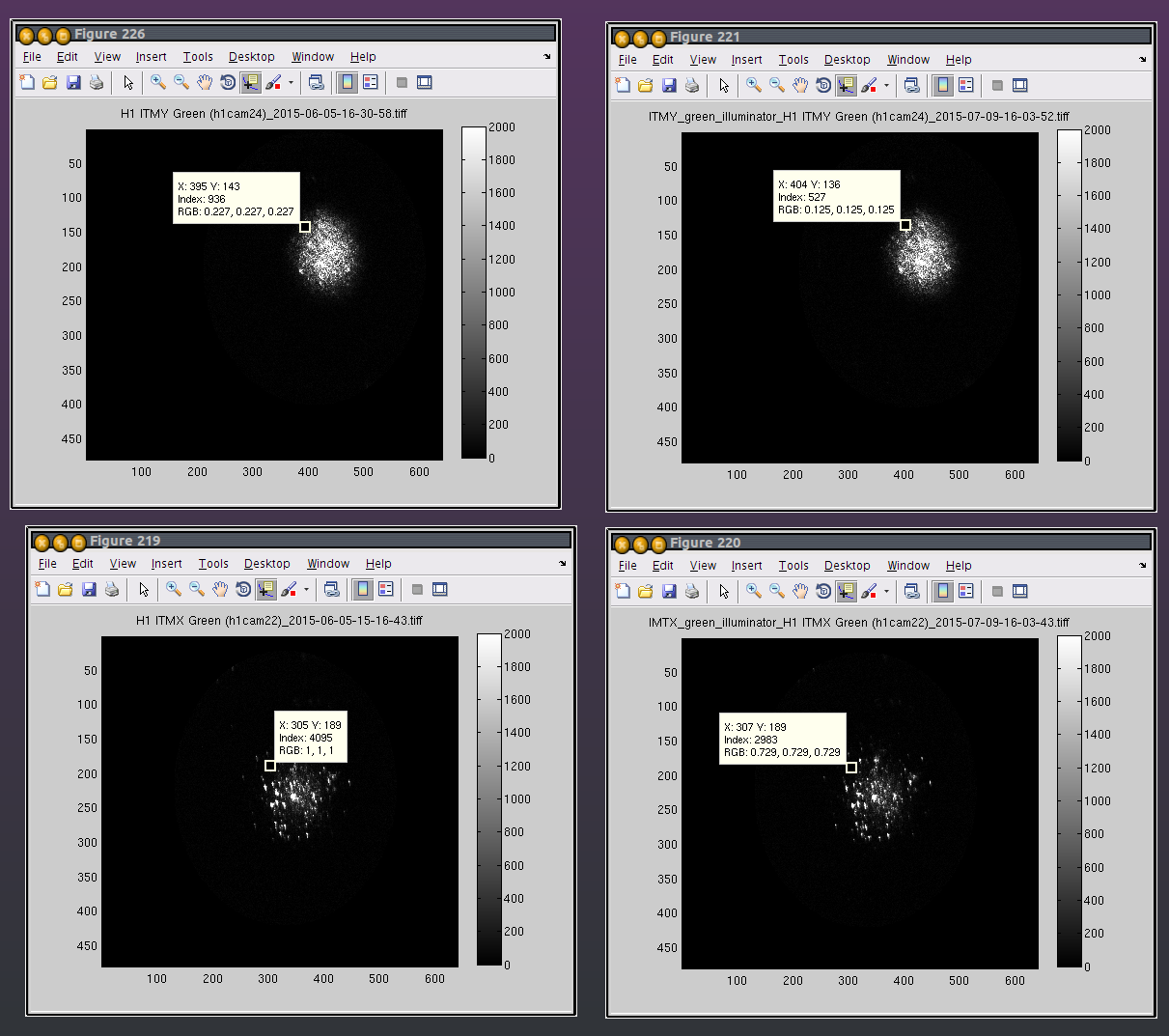
H1:ALS-Y_CAM_ITM_PIT_OFS 303.9
H1:ALS-Y_CAM_ITM_YAW_OFS 433.5


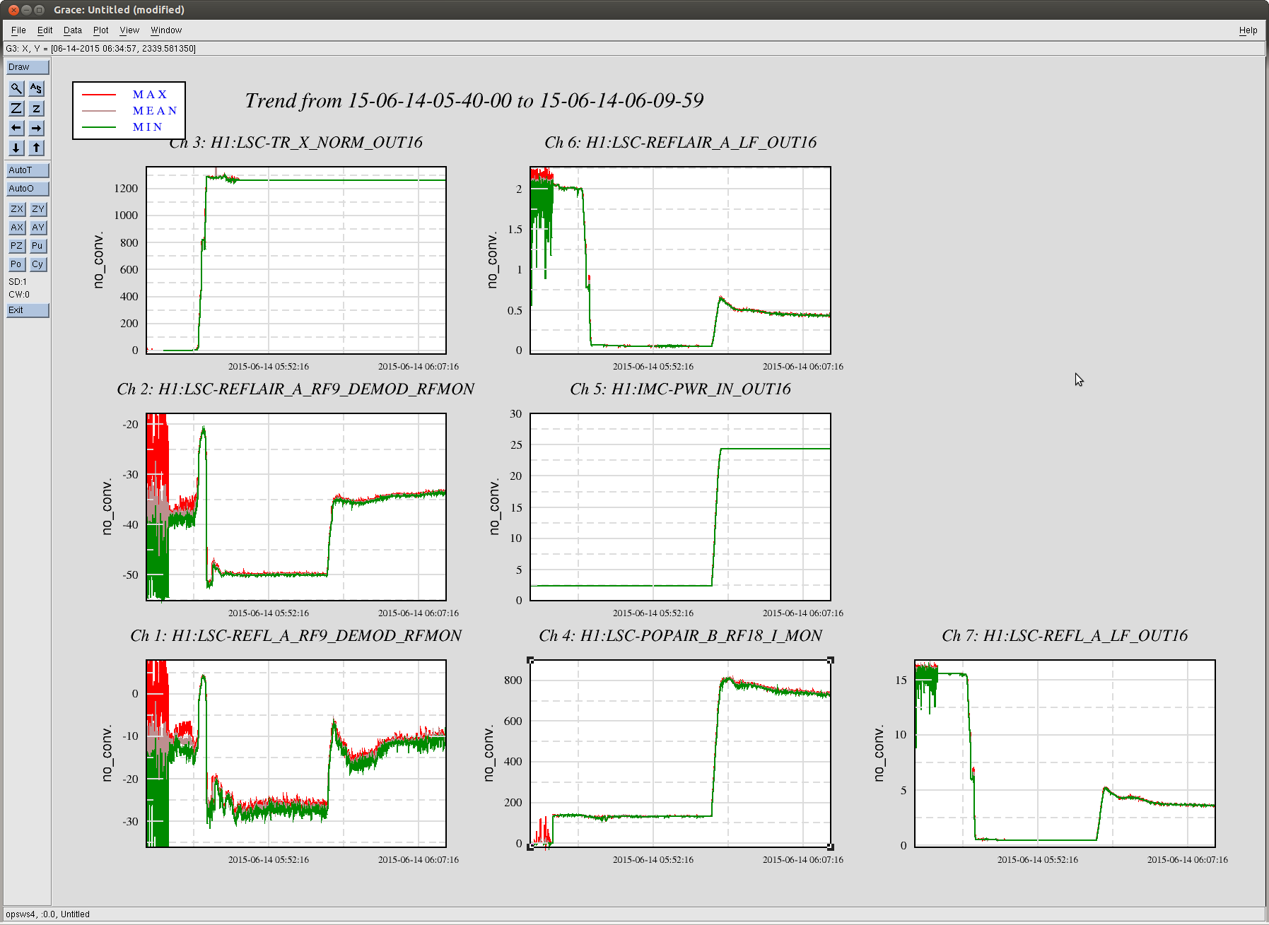


Screen shots of several of these ALS locklosses that seemed to go away after a few hours.
We've had a similar problem this morning. We saw one glitch at around 18:11:24 UTC, at this time we were sitting with only the arms locked and tidal from the green PDH to the ETMs.
Now the problem has gone away on its own again.