dipongkar.talukder@LIGO.ORG - posted 12:25, Thursday 25 June 2015 (19323)
Jitter tuning improvement stable during ER7
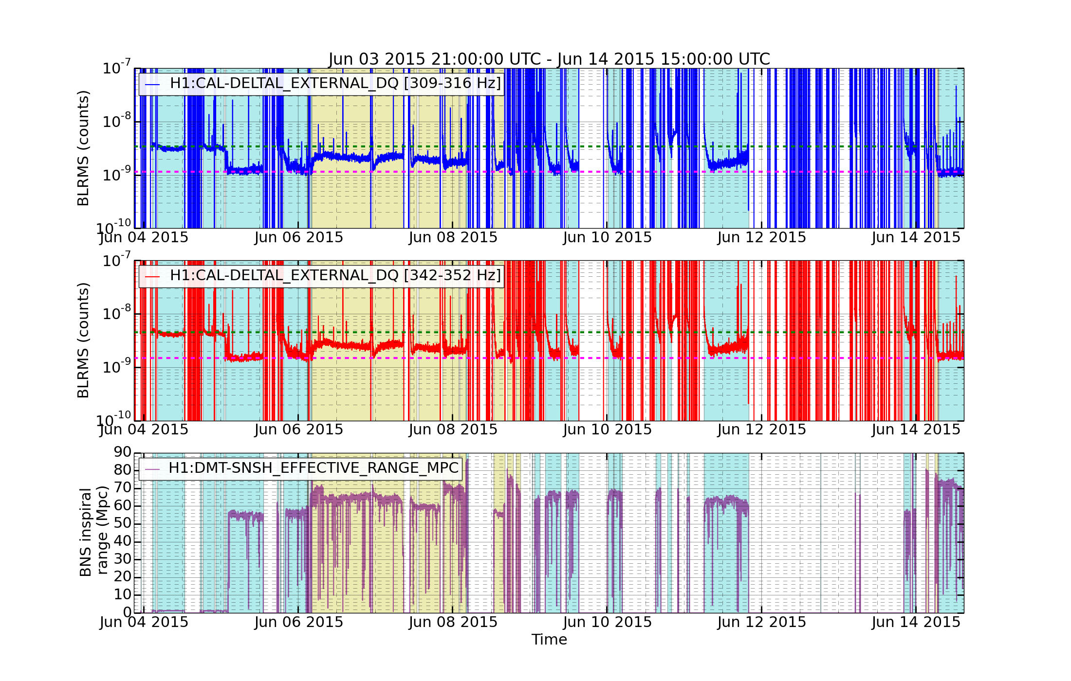
During ER7, the alignment of the IMC was adjusted to minimize the jitter peaks in DARM around 312 and 347 Hz (Link). We examine the stability of the tuning here. The top two traces in the figure are BLRMS bands centered on the peaks, and the tuning is the sharp drop at the left of the plot. The dashed horizontal lines on the plots show the pre-tuning and post-tuning level.

The tuning seems to have been fairly stable, the peak height at the end of the run was about what it was right after tuning. The peak height increased during the period when the power was increased to 24 W, which is indicated on the plot by a yellow background. This was expected because the alignment was not retuned for this power. But when the power was returned to about 17W (cyan background) the tuning returned to its good state.

The main drawback that we found was that the peak height started high after each lock and drifted down to the tuned level over tens of minutes.

Dipongkar Talukder & Robert Schofield
Images attached to this report