cheryl.vorvick@LIGO.ORG - posted 19:28, Thursday 28 May 2015 - last comment - 21:25, Thursday 28 May 2015(18677)
H1 Intent Bit Test: set at 2:18:50 UTC, but lock should be scrutinized closely before use
At 2:18:50 UTC the IFO reached LSC_FF and I engaged the Intent Bit as a test, since Jaime had just had me load new code into the ISC_LOCK guardian, that will unset the Intent Bit at lock loss.
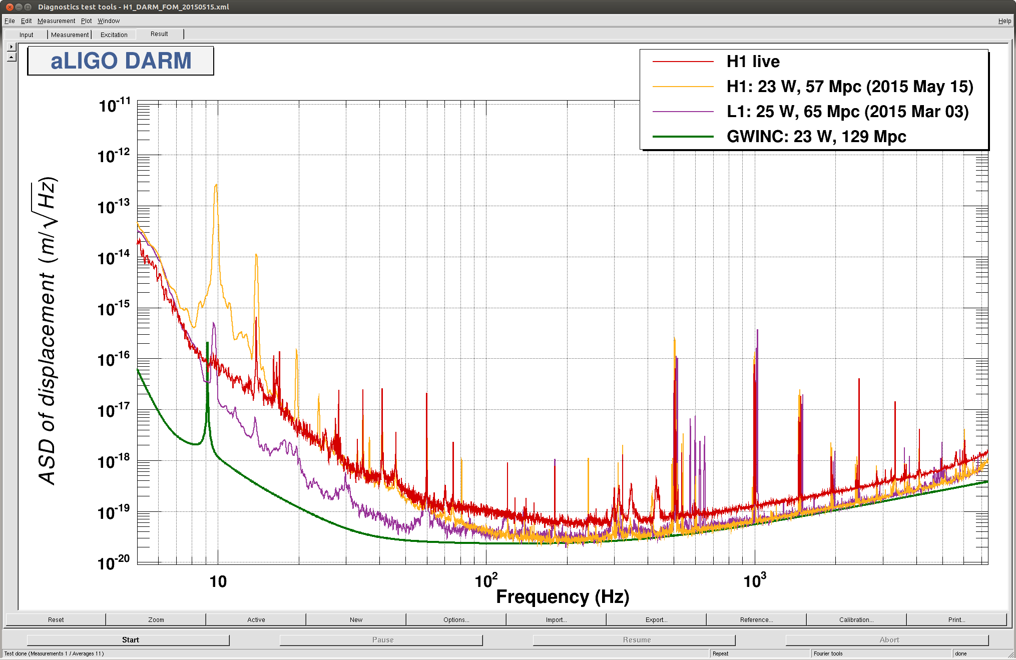
NOTE: This lock stretch IS NOT at about 60Mpc - the calibration is KNOWN TO BE INACCURATE, and is being worked on.
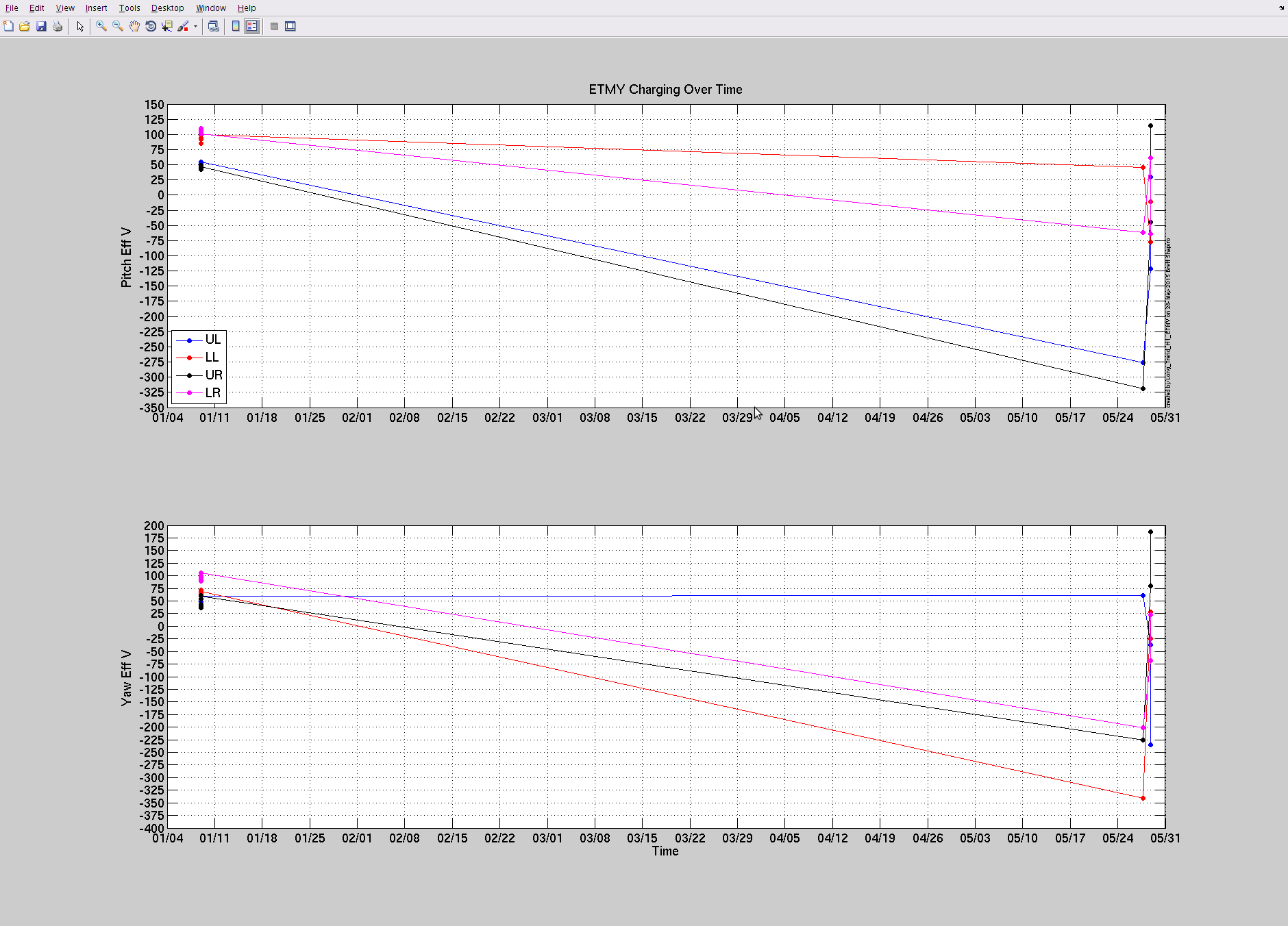
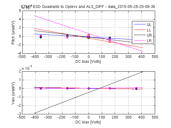
ETMY ESD is saturating constantly, so while I set the Intent Bit as a test, this lock stretch is of QUESTIONABLE USE for data analysis.


2:32 UTC, lock loss and Intent Bit is still green, calling Jaime.
Hopefully addressed. See comment to previous post.