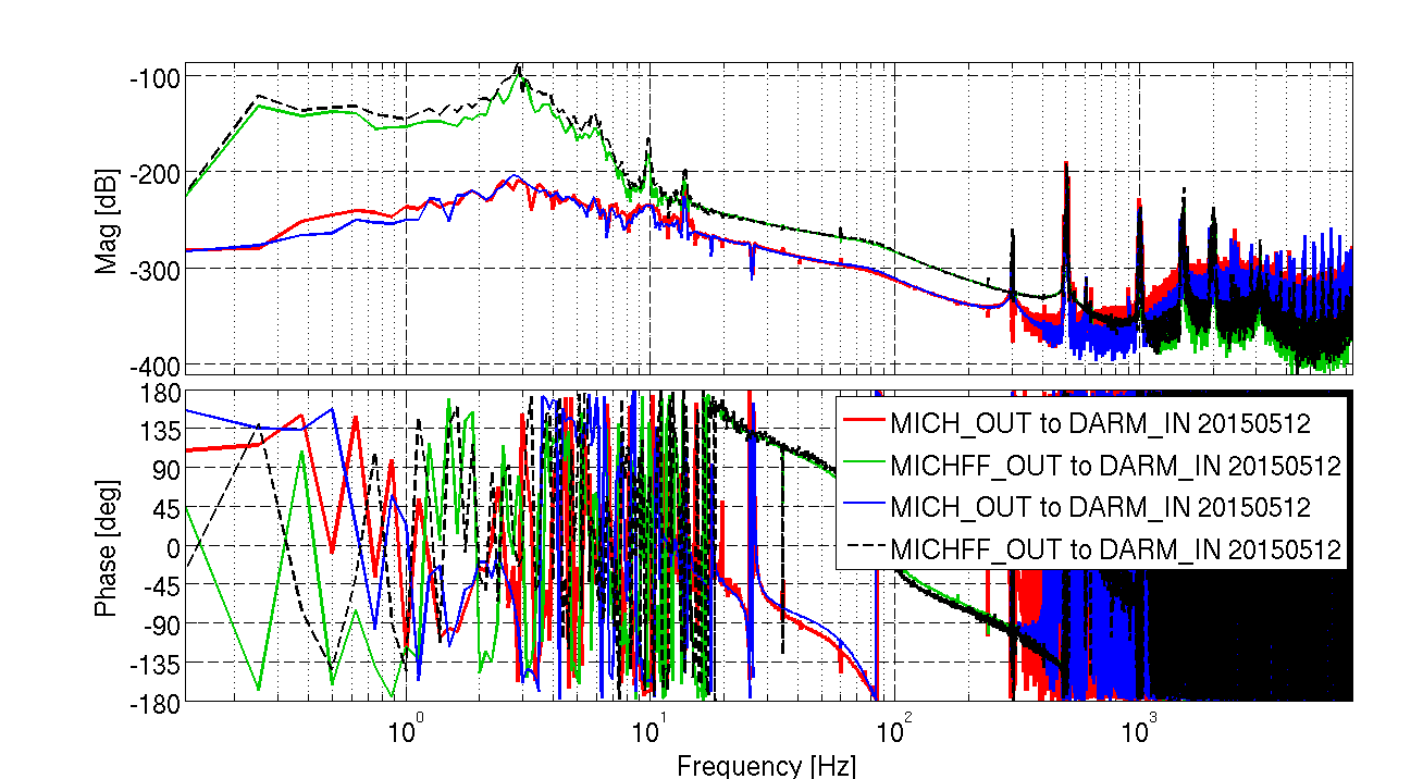
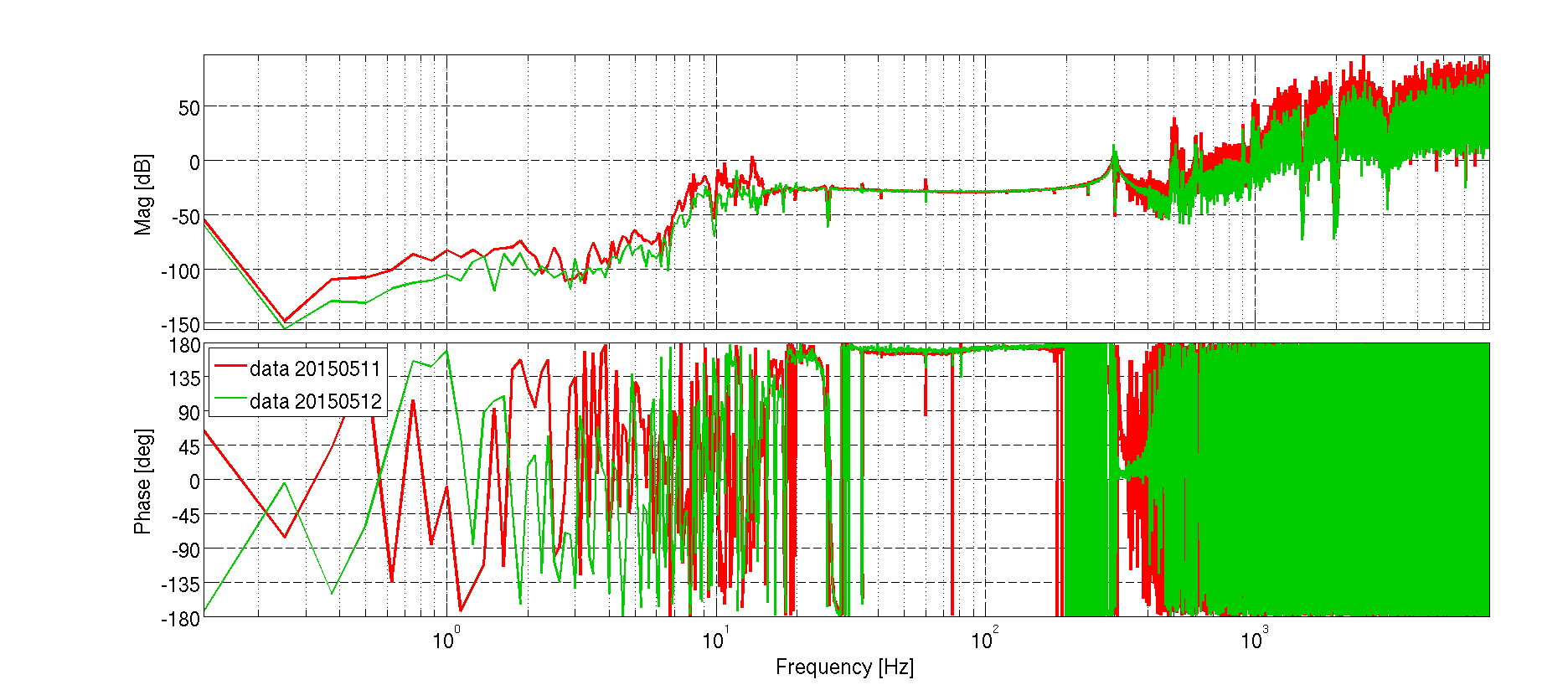
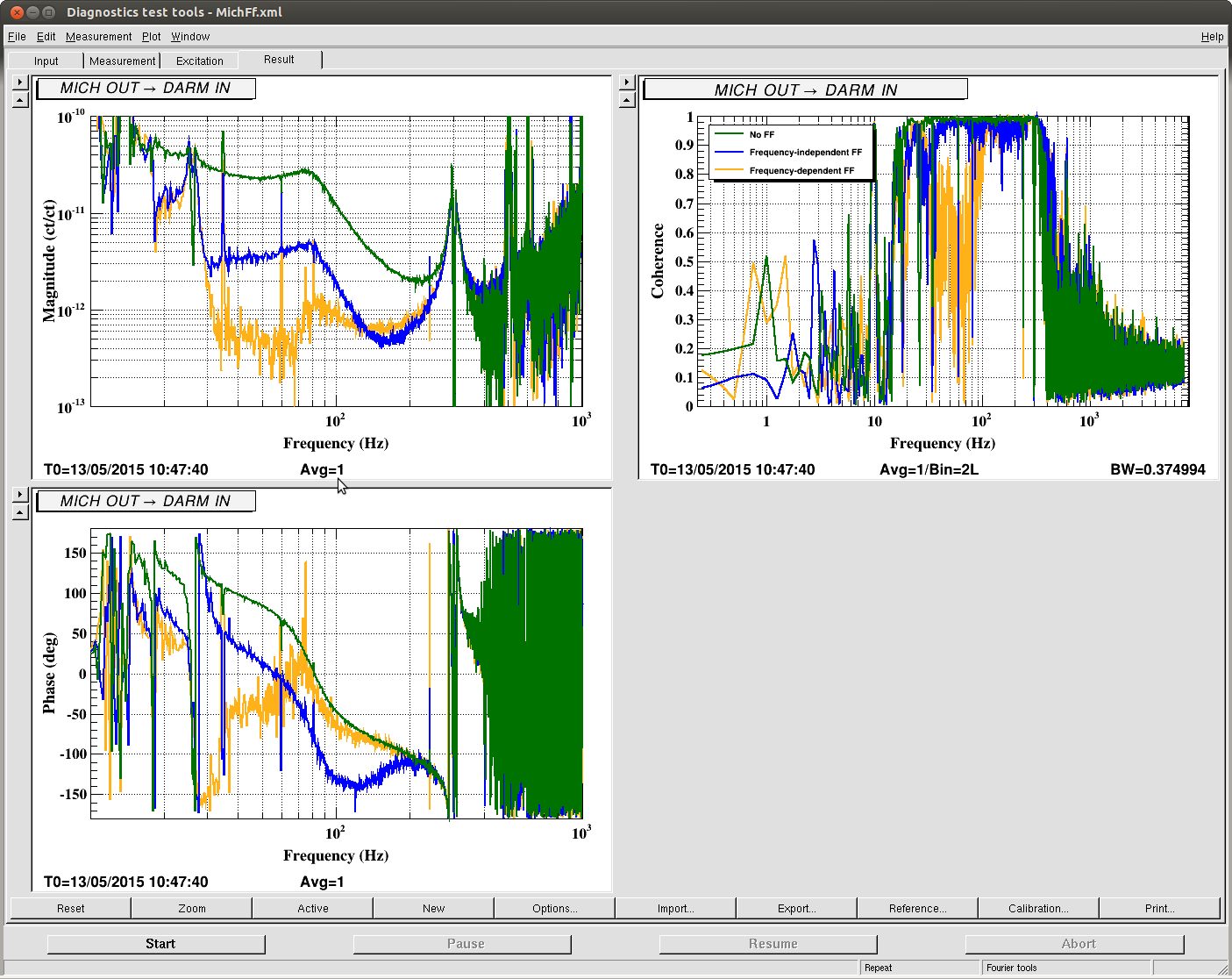
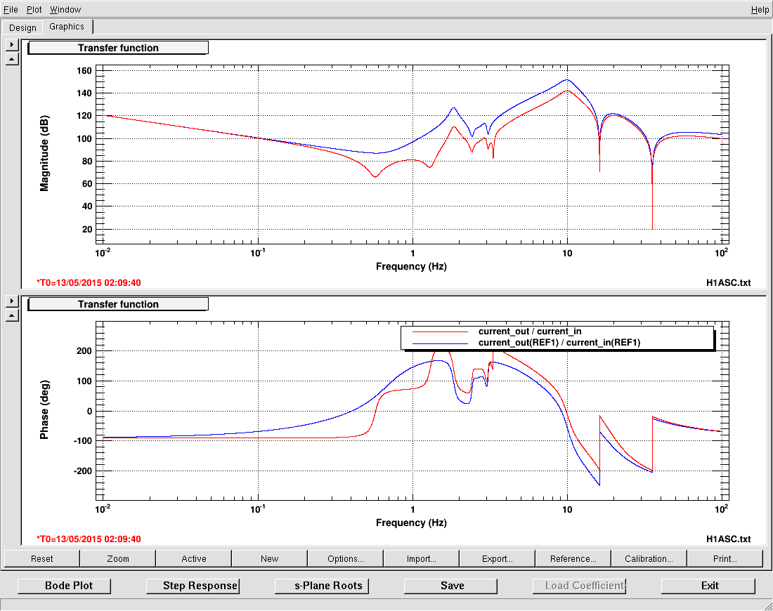
Displaying reports 70221-70240 of 77067.Go to page Start 3508 3509 3510 3511 3512 3513 3514 3515 3516 End
Reports until 12:23, Friday 12 July 2013
LHO General
patrick.thomas@LIGO.ORG - posted 12:23, Friday 12 July 2013 (7063)
moved dust monitor at location 15 in the LVEA
I moved this dust monitor under the clean room over HAM 5 and 6.
LHO VE
kyle.ryan@LIGO.ORG - posted 12:00, Friday 12 July 2013 (7062)
Vacuum related work around HAM 1
Kyle - 
Added and torqued door bolts on HAM 1 East and West doors this morning in order to get doors to seal against their O-rings -> Pumped/vented HAM1/HAM2 annulus volume multiple times -> Helium signal 6.5 x 10⁻⁷ torr*L/sec (Fine Test Mode) before Pump/Vents and 4.5 x 10⁻⁷ torr*L/sec (Fine Test Mode) after Pump/Vents -> this may or may not be significant
H1 SEI
hugo.paris@LIGO.ORG - posted 10:27, Friday 12 July 2013 (7061)
HAM-ISI - Remaining Ground Sensors Connected

Filiberto, Hugo

The 2 remaining ground STSs were connected to the HAM electronics racks. Signals are broadcasted to the ISI models. HEPI models need to be updated to receive those signals.

H1 SEI
hugo.paris@LIGO.ORG - posted 09:20, Friday 12 July 2013 (7060)
HAM6-ISI - Chamber-Side testing report

The chamber-side testing of HAM6-ISI was performed last week. HAM6-ISI Chamber-Side Testing Report is now available under the DCC.

H1 AOS
lisa.austin@LIGO.ORG - posted 09:08, Friday 12 July 2013 (7059)
SLC - Manifold Cryopump assembly and installation
Thursday, 11 July 2013

Gerardo Moreno, Scott Shankle, Mike Vargas, Nichole Washington

Weldments and Cylinder were unwrapped and brought into the cleanroom with the help of Apollo.

Weldments were assembled to Cylinder. 
Assembly was difficult because the holes are to small, no room for adjustment of parts. Hole diameter on Weldments and Cylinder is 0.209". Screw diameter is 0.190". All 35 locations were mated. 
Holes should be reamed out for future assemblies.

pics 1 and 2 - teamwork
pic 3 - buttoning up
pic 4 - end of the day

Time spent on actual assembly for the day was ~4 hours.
Images attached to this report
H1 CDS
james.batch@LIGO.ORG - posted 09:03, Friday 12 July 2013 (7058)
/ligo on cdsfs0 Read-Only, Restarted
The /ligo file system on cdsfs0 was found in a read-only state.  I powered down cdsfs0, then restarted.

NOTE: cdsfs1 may have lost a disk from it's RAID. Investigation ongoing. 
H1 DAQ
david.barker@LIGO.ORG - posted 21:54, Thursday 11 July 2013 (7057)
LDAS upgraded QFS writer, h1fw0 restarted

Dan upgraded h1ldasgw0 to Solaris 11.1 SRU 8.4.0 (same as LDAS) and added multipathing support for the Nexsan SATAboy2. I have just restarted h1fw0. We will see if the upgrades help the instability problems with h1fw0.

H1 CDS
david.barker@LIGO.ORG - posted 17:43, Thursday 11 July 2013 (7056)
h1iscex IO Chassis swapped out, h1oaf0 IO Chassis relocated from LVEA to CER

We swapped out the IO Chassis for h1iscex with one having the correct number of ADC cards (built by using two TCS chassis). h1iscex now has the required 3 ADC cards and one 16bit DAC.

The IO Chassis for h1oaf0 was relocated from the LVEA teststand area to the PEM rack in the H1 CER. We used the onestop fiber cable already run for this Chassis.

H1 ISC
alexan.staley@LIGO.ORG - posted 17:23, Thursday 11 July 2013 (7054)
PDH Error Signal of REFL Beam

(Stefan, Alexa)


We calibrated the PDH locking signal of the REFL beaming using Stefan's calibration scheme below (reference SUGWG lab logbook):

Motivation:
Easy way to calibrate a PDH error signal in Hz/Volt.

Input:
* Cavity pole frequency f0 (See next entry on how to measure this.)
* Maximum (peak) voltage of the error signal in a slow cavity scan: Vmax

Result: gain at lock point = f0/(2*Vmax)

Description:
The cavity resonance amplitude transfer function can (for high finesse cavities) be accuracy described by a Lorentizan:

TF = 1/(1+if/f0)

where f is the frequency offset from resonance. A phase modulated carrier field

Psi = 1 + i*exp(iwt) +i*exp(-iwt)

thus becomes

Psi_r = 1/(1+if/f0) + i*exp(iwt) +i*exp(-iwt)

The DC and 1-w part of |Psi_r|^2 are therefore

|Psi_r|^2 = 1/(1+(f/f0)^2) * ( 1 + [(1+if/f0)*(+i) + (1-if/f0)*(-i)]*exp(iwt) + C.C. )

Therefore the DC PDH error signal is

error/2 = [(1+if/f0)*(+i) + (1-if/f0)*(-i)] / (1+(f/f0)^2) = -2(f/f0) / (1+(f/f0)^2)

This has a maximum of 1 for f=f0 (see attached hand-written note). Therefore the full calibrated error signal is (sign omitted)

PDH_error = 2*Vmax*(f/f0) / (1+(f/f0)^2)

which has the slope 2*Vmax/f0 [Volts/Hz] around the locking point.


I created a script that imports the transmitted light (H1:ASC-Y_TR_A_NSUM_OUT_DQ) and reflected light (H1:LSC-REFLAIR_A_RF9_I_OUTMON) data. With this data, we follow the above calibration and create a fit. The script and results are attached. The graphs include the collected data and the calibration fit. The graph of the REFLAIR channel also includes the gain locking slope in red. From fitting the calibration to the data we succeeded in making a cavity pole meaurement of 82Hz. We also found the peak of REFLAIR to be 550 counts.

Images attached to this report
Non-image files attached to this report
H1 SUS
arnaud.pele@LIGO.ORG - posted 17:10, Thursday 11 July 2013 (7055)
BS top mass sensors @ 60Hz ?

The input sensor signal of the top mass of the beamsplitter have been moving suspiciously for two days.

Attached is a spectra showing a comparison of F1 top mass sensor on July 09th 2013 at 13:00 PT (pink) and same day at 14:00 PT (blue). The blue curve is higher at around 60Hz which might be why we see the anomalous signal on the osems. The second level of the suspension , and stage 2 of the ISI are not moving at this frequency (cf second pdf).

Non-image files attached to this report
H1 SEI
hugo.paris@LIGO.ORG - posted 16:45, Thursday 11 July 2013 (7053)
HAM3-ISI - Sensor Correction

STS calibration filters, and Sensor Correction from the corner station ground STS to the CPSs, were installed on HAM3-ISI today.

Performance spectra were taken. Plots are attached.

One can notince improvement in the 1Hz-6Hz region, especially along Z.

Non-image files attached to this report
LHO General
patrick.thomas@LIGO.ORG - posted 16:41, Thursday 11 July 2013 (7047)
Ops Summary
Praxair delivered LN2 to the end X cyropump tank.
8:45 Filiberto left to turn on the small clean room between HAM 2 and HAM 3 and pull accelerometer cables. (WP 403) The clean room had been turned off for noise measurements.
~9:00 The small clean room between HAM 2 and HAM 3 was turned on.
9:58 Colin S. and Pablo D. headed out to the H2 PSL enclosure to work on PCAL.
12:39 Jeff B. and Andres headed out to work in the end X TMS lab.
1:09 Dave B. shutdown the h1oaf frontend. (WP 4029)
1:22 Colin S. and Pablo D. left the H2 PSL enclosure for lunch.
2:28 Colin S. and Pablo D. headed out to the H2 PSL enclosure to work on PCAL.
2:45 Corey G. went to the end X lab.
3:15 Dave B. powered down h1fw0 to allow Dan to patch the QFS file system.
3:38 Dave B. powered down the h1iscex frontend to swap its IO chassis.
H1 SUS
mark.barton@LIGO.ORG - posted 16:32, Thursday 11 July 2013 - last comment - 13:10, Sunday 14 July 2013(7049)
TipTilt Screen Updates

I did a major cleanup of the Tip-Tilt screens and linked them to the LHO SITEMAP.

I created argument macro files $(USERAPPS)/asc/common/medm/asc???_overview_macro.txt with all the optic-specific arguments (analogous to $(USERAPPS)/sus/common/medm/sus???_overview_macro.txt for SUS). I then went through all the screens in $(USERAPPS)/asc/common/medm/asctt with gedit, changing link arguments to look like the following:

args="%(read $(USERAPPS)/asc/common/medm/asc$(optic)$(num)_overview_macro.txt),USERAPPS=$(USERAPPS),SITE=$(SITE),site=$(site),IFO=$(IFO),ifo=$(ifo)"

Formerly some of the screens expected $(OPTIC) to be the full optic name, and some used $(OPTIC)$(num), so I changed everything to the latter convention.

Details of which files were touched are at end. I want to do one more round of checking for errors, so I haven't yet committed the changes yet.

No change:

ASC_CUST_TIPTILT_DAC_MONITOR.adl, ASC_CUST_TITPTILT_SAFE_SNAP_CMD.adl

Basic updates:

ASC_CUST_TIPTILT_BIO.adl, ASC_CUST_TIPTILT_DC_ALIGN.adl, ASC_CUST_TIPTILT_M1_COILOUTF.adl, ASC_CUST_TIPTILT_M1_DAMP.adl, ASC_CUST_TIPTILT_M1_DRIVEALIGN.adl, ASC_CUST_TIPTILT_M1_EUL2OSEM.adl, ASC_CUST_TIPTILT_M1_LOCK.adl, ASC_CUST_TIPTILT_M1_OPTICALIGN.adl, ASC_CUST_TIPTILT_M1_OSEM2EUL.adl, ASC_CUST_TIPTILT_M1_OSEM_ALIGN.adl, ASC_CUST_TIPTILT_M1_OSEM_ALIGN_counts.adl, ASC_CUST_TIPTILT_M1_OSEM_ALIGN_??ZOOM.adl, ASC_CUST_TIPTILT_M1_OSEMINF.adl, ASC_CUST_TIPTILT_M1_SENSALIGN.adl, ASC_CUST_TIPTILT_M1_WD.adl, ASC_CUST_TIPTILT_M1_WD_ACT_BANDLIM.adl, ASC_CUST_TIPTILT_M1_WD_OSEMAC_BANDLIM.adl, ASC_CUST_TIPTILT_M1_WD_OSEMDC_BANDLIM.adl, ASC_CUST_TIPTILT_MONITOR_OVERVIEW.adl, ASC_CUST_TIPTILT_OPLEVINF.adl, ASC_CUST_TIPTILT_OPLEVINF1.adl, ASC_CUST_TIPTILT_OSC.adl, ASC-TIPTILT_Main.adl, newDisplay.adl

More complicated fixes:

ASC_CUST_TIPTILT_DACKILL.adl: fixed broken link to GDS_TP screen.

Broken - needs redesign:

ASC_CUST_TIPTILT_M1_DEMOD.adl, ASC_CUST_TIPTILT_M1_TEST.adl: need to fix links to $(USERAPPS)/cds/common/medm/FILTALH.adl (2 places)

ASC_CUST_TIPTILT_BIO_all.adl, ASC_CUST_TIPTILT_MONITOR_OVERVIEW_all.adl, ASC_CUST_TIPTILT_OVERVIEW_all.adl: only allows for four (not five) TTs.

Comments related to this report
mark.barton@LIGO.ORG - 14:14, Friday 12 July 2013 (7065)

Additional fixes and non-fixes:

ASC_CUST_TIPTILT_ADC_MONITOR.adl: I removed display of /cvs/cds/llo/scripts/utilities/nova_logo.gif, which was not only LLO-specific but shouldn't have been in a custom screen.

ASC_CUST_TIPTILT_BIO_all.adl, ASC_CUST_TIPTILT_MONITOR_OVERVIEW_all.adl, ASC_CUST_TIPTILT_OVERVIEW_all.adl: did not attempt to add provision for fifth optic - no room on screen.

ASC_CUST_TIPTILT_M1_DAMP.adl, ASC_CUST_TIPTILT_M1_DEMOD.adl, ASC_CUST_TIPTILT_M1_TEST.adl: I got the L1-specific links from various "GUARDIAN SET" buttons pointing to the apparently intended screen, $(USERAPPS)/cds/common/medm/FILTALH.adl, and made the asgs list more standard, but there was a $(channel) argument missing, so I couldn't getting it working fully. It doesn't seem to work at LLO either, so I leave it to the Guardian folks to take further.

I svn added the macro.txt files and committed all the changes. LLO should hopefully be able to svn up with no breakage, although care should be exercised.

mark.barton@LIGO.ORG - 13:10, Sunday 14 July 2013 (7078)

I made a few more last-minute fixes based on things I noted during the HAUX cleanup (TipTilt screens were adapted from HAUX):

ASC_CUST_TIPTILT_M1_DAMP.adl, ASC_CUST_TIPTILT_M1_DEMOD.adl, ASC_CUST_TIPTILT_M1_TEST.adl: I deleted several buttons that appeared to be an ancient attempt at a wiki-style help system at LLO (when clicked on they would try to edit files in /cvs/cds/llo).

ASC_CUST_TIPTILT_OSC.adl: I added a $(IFO) $(OPTIC)$(num) display string to screen to make it obvious what optic it related to.

ASC_CUST_TIPTILT_DAC_MONITOR.adl: I removed an attempt to display /cvs/cds/llo/scripts/utilities/nova_logo.gif, and moved the hidden date string display into the visible area of the window.

These fixes were also committed.

H1 SEI
hugh.radkins@LIGO.ORG - posted 16:26, Thursday 11 July 2013 (7052)
WHAM6 ISI is in the Chamber
Lots of unfilled schedule promises on my part this week but finally yes, the ISI is now in the chamber.  No real issues to report on this just the usual it takes a while to set things up and turn a lot of bolts.  Actually the roll into the chamber was one of the easiest with the fixture well positioned and centered.

Job well done on the Prep with DevilEd, Scott, Randy, Greg & Mitchell, directed by Jim.
LHO VE
kyle.ryan@LIGO.ORG - posted 16:14, Thursday 11 July 2013 (7051)
Pumped HAM 4 annulus
This volume had been vented until pumped this afternoon -> No change on the helium signal but there was a small response in total pressure indicating small inner O-ring leak on septum -> will leave under vacuum
LHO VE
kyle.ryan@LIGO.ORG - posted 12:01, Thursday 11 July 2013 (7050)
HAM1
As part of our hunt for helium sources - today I pumped the HAM1/HAM2 annulus volume briefly with a scroll pump but stopped as the system wasn't sealed enough -> The East door of HAM1 is currently hung on (4) door bolts and is likely not in full contact with its O-rings -> I UltraTaped the outside of HAM1's East door flange and again pumped the annulus volume but stopped as I deduced that a leak via the inner O-ring was apparent -> As such, the interior of HAM1 may have experienced some "wind"
H1 AOS
lisa.austin@LIGO.ORG - posted 23:21, Wednesday 10 July 2013 (7046)
SLC - Manifold Cryopump assembly and installation
SLC Team and Apollo

Cleanroom footprint was expanded to the wall (pic 1). 
Weldments, Face Plates and Cylinder were moved into the LVEA (pic 2).
Assembly/Installation Fixture and Balancing Fixture were moved into position (pic 3).
It was identified that the Gate Valve Annulus Piping needs to be removed for installation of baffle (pic 4). This was discussed with John Worden and approved.
Team will begin assembly in the AM after cleanroom has been wiped down and particle count is acceptable.

The large tooling has been at LHO for about two years. The Pusher Brackets which are needed for balancing have not been located. The team will request parts be sent overnite from LLO.
Images attached to this report
H1 ISC
stefan.ballmer@LIGO.ORG - posted 20:27, Wednesday 10 July 2013 (7045)
REFLAIR_A_RF9 commissioning
(Alexa, Daniel, Stefan)

We

 - debugged the shutter software, and got it to work
 - switched the shutter control cables between shutter control 2 and 3
 - set up the appropriate threshold for the shutter (0V)
 - placed an iris in the main beam path to guarantee that the shutter protects the RFPD
 - verified the safety of the RFPD by moving PRM, and measuring the max power out of the RFPD.
 - aligned the RFPD to the weak ITMY reflected beam (with the PRM misaligned)
 - switched the supply cables between POPAIR_A and REFLAIR_A (they are now going to the right input)
 - verified that we see fringes on the DC readback
 - turned on the REFLAIR_A_RF9_LF power supply, verified that all whitening is 0
 - verified that we get a signal in H1:LSC-REFLAIR_A_LF_OUT
 - moved the RF cable to the REFLAIR demodulation board (i.e. the signal currently does not go to the real common mode board)
 - verified that we have a signal in H1:LSC-REFLAIR_A_RF9_I_OUT
 - verified that its whitening is all off
 - tried to lock the arm cavity, but had excessive pitch motion

PS:
 - The RefCav is still pretty lame in re-locking
H1 AOS
keita.kawabe@LIGO.ORG - posted 18:34, Wednesday 10 July 2013 - last comment - 18:43, Wednesday 10 July 2013(7043)
TMSX primary off-axis parabolic is too thin (Corey, Keita)

The primary parabolic mirror of H1 TMSX turned out to be about 80 to 100 thousandth of an inch thinner than in the DCC drawing (https://dcc.ligo.org/LIGO-D1000075).

The thickness at the thinnest and the thickest edge were measured to be [1.608", 2.868"] VS [1.69, 2.97] in the DCC drawing.

The specification (https://dcc.ligo.org/LIGO-E0900347) states that it should be 43+-1mm or 1.693+-0.039" at the thinnest edge.

OTOH, the manufacturer certificate of compliance (https://dcc.ligo.org/LIGO-E1300278) states that the spec is 41+-1mm or 1.614+-0.039", presumably at the thinnest edge, that's about 80 thousands right there. Either the mfg or the spec document is wrong.

Either way, the consequence is that the mirror thickness as of now is outside of the adjustment range of clamps, and the clamps don't touch the optic at all. 

Bottom two clamps: You can easily insert a 25 thou metal between the mirror and the bottom clamps (picture), but I couldn't slip 50 thou washer.

Top clamp: I didn't want to risk dropping a metal piece on the center of the optic, so I didn't slip anything to the top. However, the top thickness is 1.608", and the clamp is designed to accomodate 1.68" or thicker optic, so it seems as if there is a 70 thou-ish gap.

After a conversation with Ken Mailand, I decided to re-machine the clamp locally to shave off 100 thousandth from the top of the clamp standoff. Hopefully Tylor can do it by the end of Thursday and Justin can slip them in the next oven load.

Images attached to this report
Comments related to this report
keita.kawabe@LIGO.ORG - 18:43, Wednesday 10 July 2013 (7044)

Note that if the claim of the mfg about the spec (41+-1 mm, presumably at the thinnest edge) is correct, the clamps don't work by design.

As explained earlier, the top clamp is designed to accomodate 1.68" (42.7mm) or thicker mirrors (see https://dcc.ligo.org/LIGO-d1002732 and https://dcc.ligo.org/LIGO-d1002731). 

However, even if the mirrors are manufactured to the spec document (43+-1 mm), if the mirror falls on a thinner side but within the spec, say at 42mm, the clamp probably does not work.

What happened at LLO?

H1 ISC
alexan.staley@LIGO.ORG - posted 19:20, Tuesday 09 July 2013 - last comment - 10:05, Thursday 11 July 2013(7032)
ISCTI Table Work

(Alexa, Stefan, Dick)


ISCT1 REFL BEAM Polarization Measurement: We used a cube to measure the polarization of the ISCT1 REFL beam out of the periscope. We found the polarization to be s-pol. 

Optics Added: With the PSL at 1Watt, the power of the ISCT1 REFL beam at the periscope is 0.68W. However, the PD on the table used as a trigger for the shutter saturates at 6mW. Thus, we placed a W1 45S beam splitter with the AR coating in front of the shutter to reflect 2mW of light onto the PD. We also placed an iris in front of the PD to single out the beam. And finally, we placed a lens in front of the PD to reduce the beam size.


Note: One of the shutter controller boxes has been modified (see LIGO-E1300580-v1); however, the top one remains to be changed. 

Comments related to this report
alexan.staley@LIGO.ORG - 10:05, Thursday 11 July 2013 (7048)

The controller that has been modified is identified by S1203608 and is shutter controller 3. Shutter controller 2 remains to be modified.

Displaying reports 70221-70240 of 77067.Go to page Start 3508 3509 3510 3511 3512 3513 3514 3515 3516 End