This seismometer has given us problems for some time: alogs 15510, 14482, 9727. JeffK may point to others too.
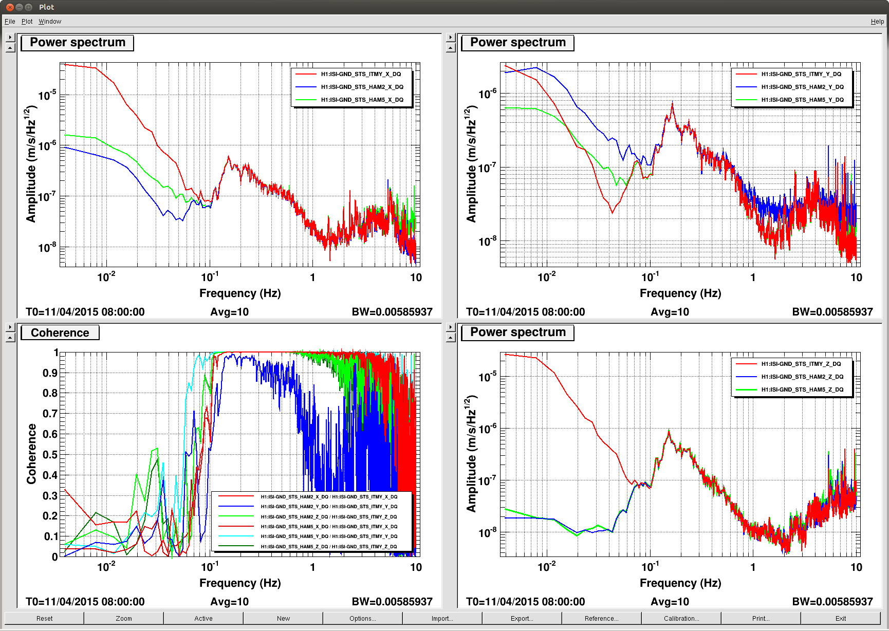
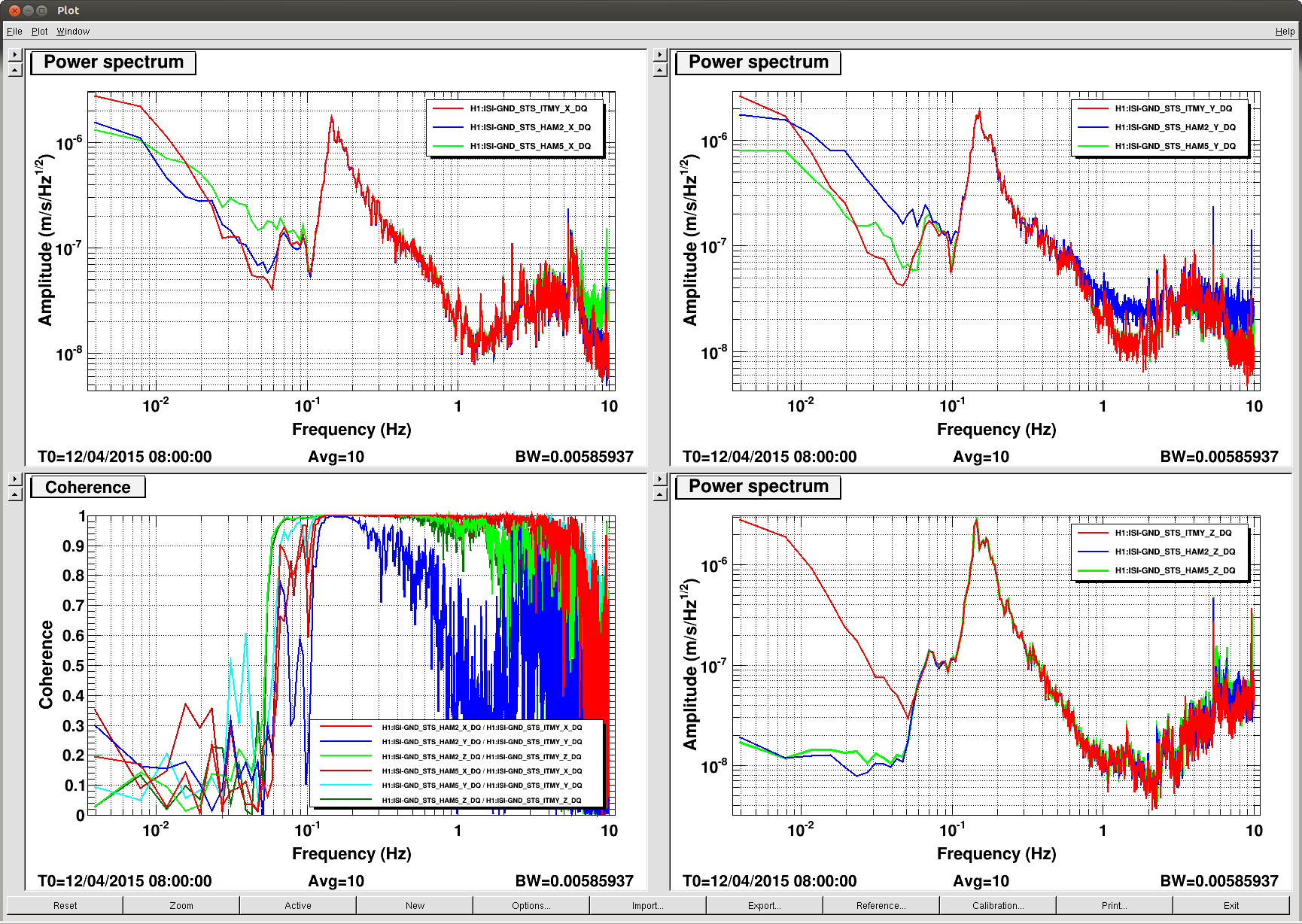
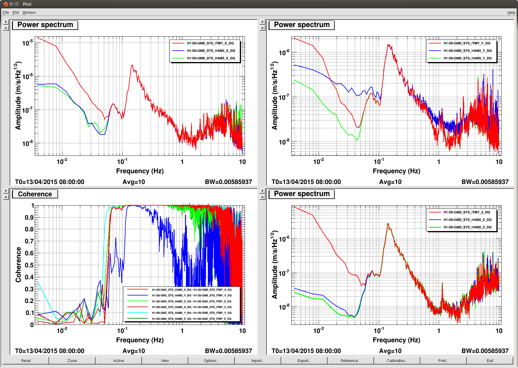
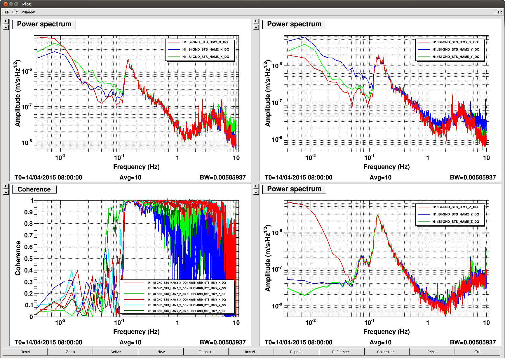
On the attached four plots, there are four successive days, Saturday thru Tuesday at 0100pdt. The lower left panels are the Coherences between the HAM2 & HAM5 (STS-A & C) and the ITMY (STS2.) The Upper Left, Upper Right, and Lower Right panels are the ASDs of the X Y & Z DOFs respectively of STS2 A B & C.
The take away is that in general the character of the ITMY (STS2-B) ground seismometer doesn't change like the other two instruments below 100mhz while the HAM2 & HAM5 instruments change more day to day and mostly look like each other.
Details: The Z DOF is most obvious in that below 50 or 80 mhz, ITMY trends up steeply while the A & C seismos do not. For the Y DOF, the HAM2 (STS2-B) signal seems to be the outlier but the day to day doesn't follow a patten between the instruments so I ... The X DOF is pretty good with the A & C instruments tracking each other pretty closely while the B sensor kinda stays at the same power level, mostly. So, like I say, a Case, maybe.
If I remember right, it sits on some kind of thin plastic or rubber mat, while the others sit directly on the concrete. If possible, it might be useful to make it contact the the concrete floor directly by carving out three holes on the mat.
For convenience:
Evidence for low-frequency broken-ness
LHO aLOG 15510
LHO aLOG 14482
LHO aLOG 9727

Factor-of-2 drop in X channel gain
LHO aLOG 16208
LHO aLOG 16305
J. Kissel, R. Schofield

Trying to convince Robert to let us borrow the newly-returned PEM vault STS-2 (S/N 88921) (see when it was removed in LHO aLOG 12931), I tried to show him in more detail with a little less curves on a plot what was wrong with the ITMY, B, Beer Garden STS-2 (S/N 88941). In the process, we not only rediscovered the problem Hugh shows above -- that the Z DOF on ITMY, below 50 [mHz] is just junk, but we also discovered that the Y DOF on the HAM2, A, Input Arm STS-2 (S/N 89922) is also junk.

The attached PDFs show 5 days worth of corner station STS2 ASDs and COHs.
For HAM2, check out the Y COH .pdf first. We see surprisingly low coherence between HAM2's Y and the other two, where the other two are perfectly coherent with each other. Looking at the ASD, it also shows the HAM2 spectra are consistently discrepant between 500 [mHz] and 3 [Hz], as well as below 0.1 [Hz].

For ITMY, again, check out the Z ASD first. From there, it's obvious that every day, the motion below 50 [mHz] is just junk. This is confirmed by the coherence, which shows that HAM2 is coherent with HAM5 every day, and ITMY is coherent with neither every day.

The fact that ITMY and the HAM5, C, Output Arm STS-2 (S/N 100145) are always coherent between ... nope I can't make a consistent story. DOFs are inconsistently coherent, where they should all be perfectly coherent from 1 [Hz] down to 10 [mHz]. We really just need to huddle test all four of the STSs we have available in the corner,
89921 "PEM" Back from Quanterra
89922 Currently STS A
89941 Currently STS B
100145 Currently STS C
and confirm -- once and for all -- which channel of whose is busted. Unfortunately, this means a whole lot of cable lugging around the LVEA -- a pretty hefty Tuesday task.

Further -- LHO really needs more low-frequency seismometers -- because
(a) We're already "temporarily" using a T240  at EX (S/N 531, borrowed fron the ETF at Stanford, originally installed at LHO in Feb 2014, see LHO aLOG 9758, and D1400077) because the project couldn't find enough STS-2s for us.
(b) Even *if* we use all 5 in our possession (we have one at ETMY, S/N 89938), we still wouldn't be able to have one fail without significant down time.

The lab's STS2/T240 Inventory, E1200068 hasn't been updated since the last time we churned up this subject in Oct 2014. I'm working on updating it myself by beating the streets; stay tuned for a -v15.

Devil's advocate (inspired by Robert):
Looking at the X DOF, there are days where all corner STSs are perfectly coherent between 60 [mHz] and ~2 [Hz].
Looking at the Y DOF, there are days where ITMY and HAM5 are perfectly coherent between 60 [mHz] and ~3 [Hz].
Looking at the Z DOF, there are days where all corner STSs are perfectly coherent between 60 [mHz] and ~1 [Hz].
The above implies that the corner station ground motion is perfectly coherent between 60 [mHz] and ~1 [Hz].
This implies we could try using a single STS-2 to run sensor correction for all chambers in the corner station.
In order of risk of common-mode rejection being compromised:
- For the BSCs, in X&Y, we only need a good signal around the first SUS resonances at ~500 [mHz] for DeRosa's narrow-band filter (See figure 3.32 P1500005).
- For the HAMs in X&Y, we only need good coherence down to the bottom (frequency) edge of Hua's polyphase FIR bump, at 50 [mHz] (See pg 4 of attachment to SEI aLOG 594)
- For all chambers, in Z, we need good coherence down to 10 [mHz], the lower end of the Mittleman's tilt free filter (See pg 5 of SEI aLOG 594)

So, *if* we find an STS we like in which off of it's DOFs are performing perfectly (hopefully, presumably it's the one that just came back from Quanterra, S/N 89921), then we might be able to get away with running the entire VEA off of one STS2 (or T240). Maybe.