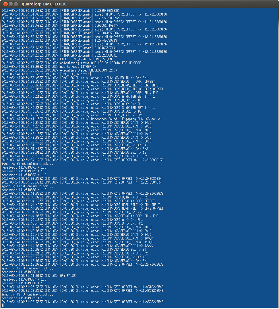
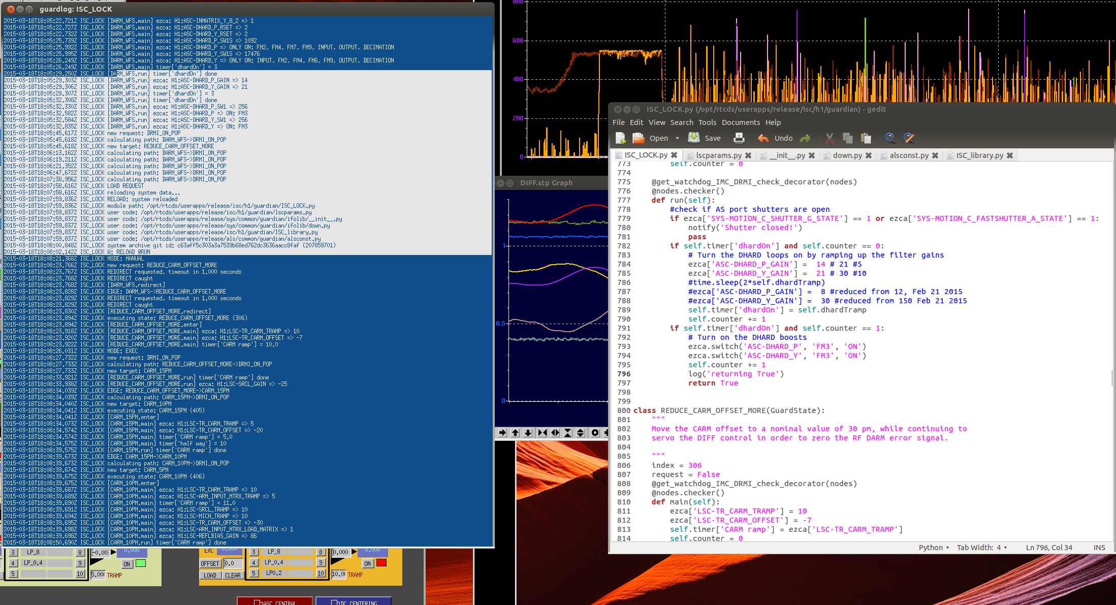
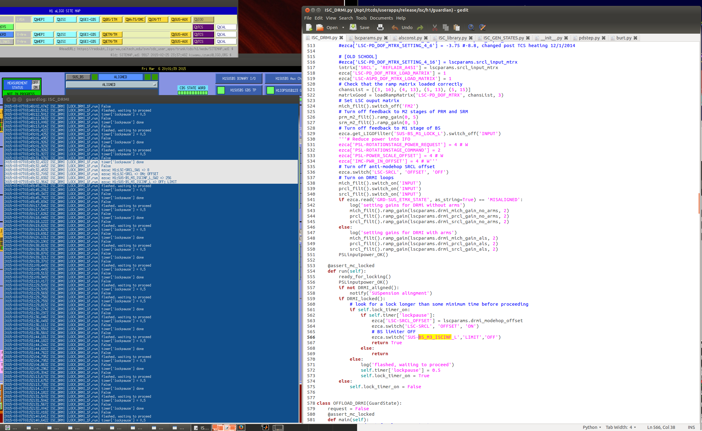
There has been an intermittent issue with the OMC_LOCK Guardian in which it runs a portion of code twice. I've observed this most often in the OMC_LSC_ON state, where the LSC controls for the OMC are ramped up. It's easy to notice, because if the gain steps are repeated for the OMC length servo the loop quickly becomes unstable and the cavity unlocks. I've noticed this happen a handful of times in the past few weeks. I've also seen lines of code in other main() function get executed twice, although I don't have screenshots to prove it.
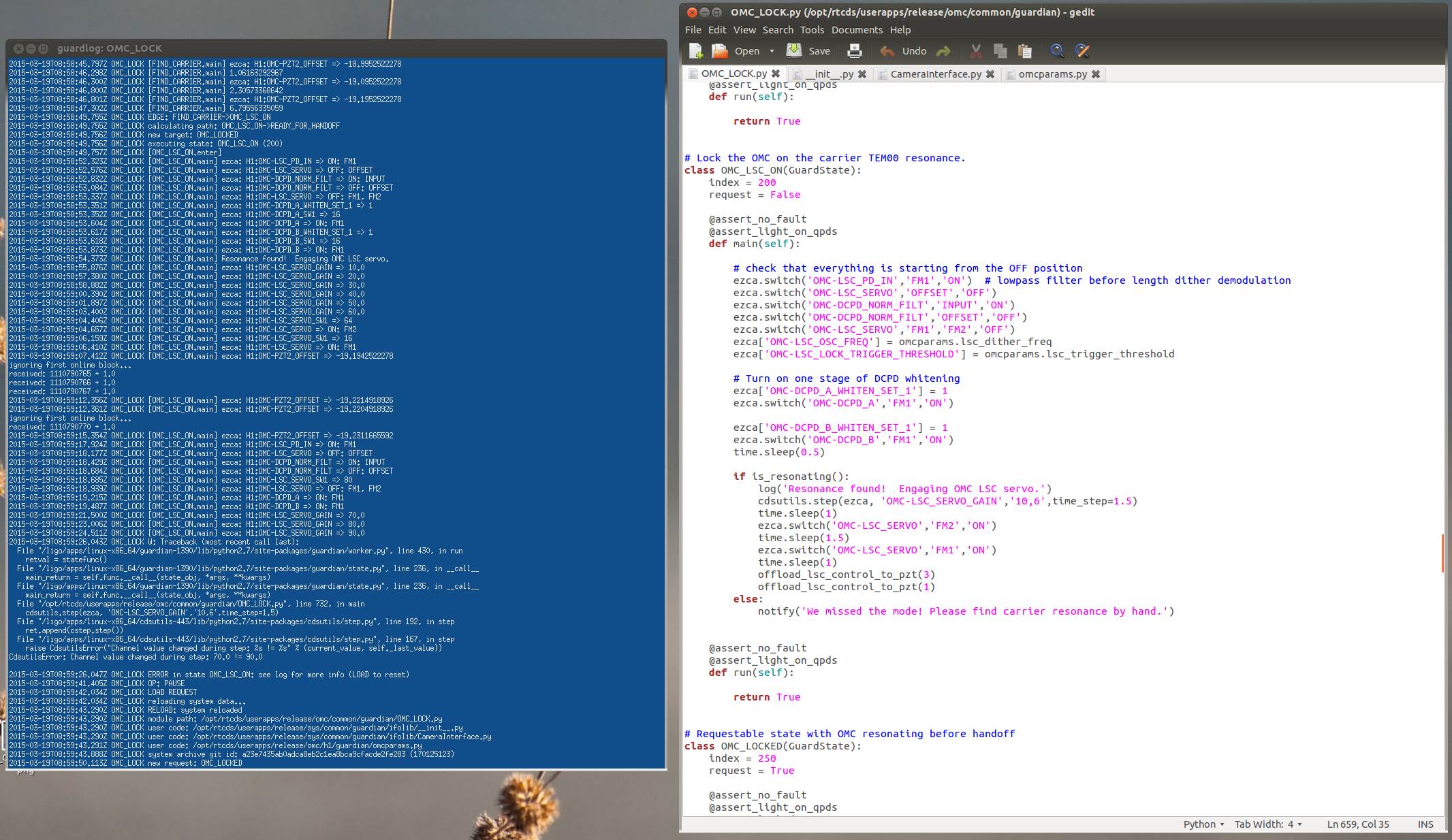
Attached are screenshots of the OMC_LOCK log, from an event last week (March 14), and another tonight. In both screencaptures, the OMC guardian enters the OMC_LSC_ON state, completes the instructions in main()...and then starts all over again. In both cases the requested state was well downstream of OMC_LSC_ON, the guardian should not have looped there. (And anyways, how does it repeat the main() function?)
I've committed the latest version of the OMC_LOCK guardian to the SVN, if experts want to check the code to make sure I'm not doing something heinous in the function calls or definitions.
In other locking notes from tonight...
-
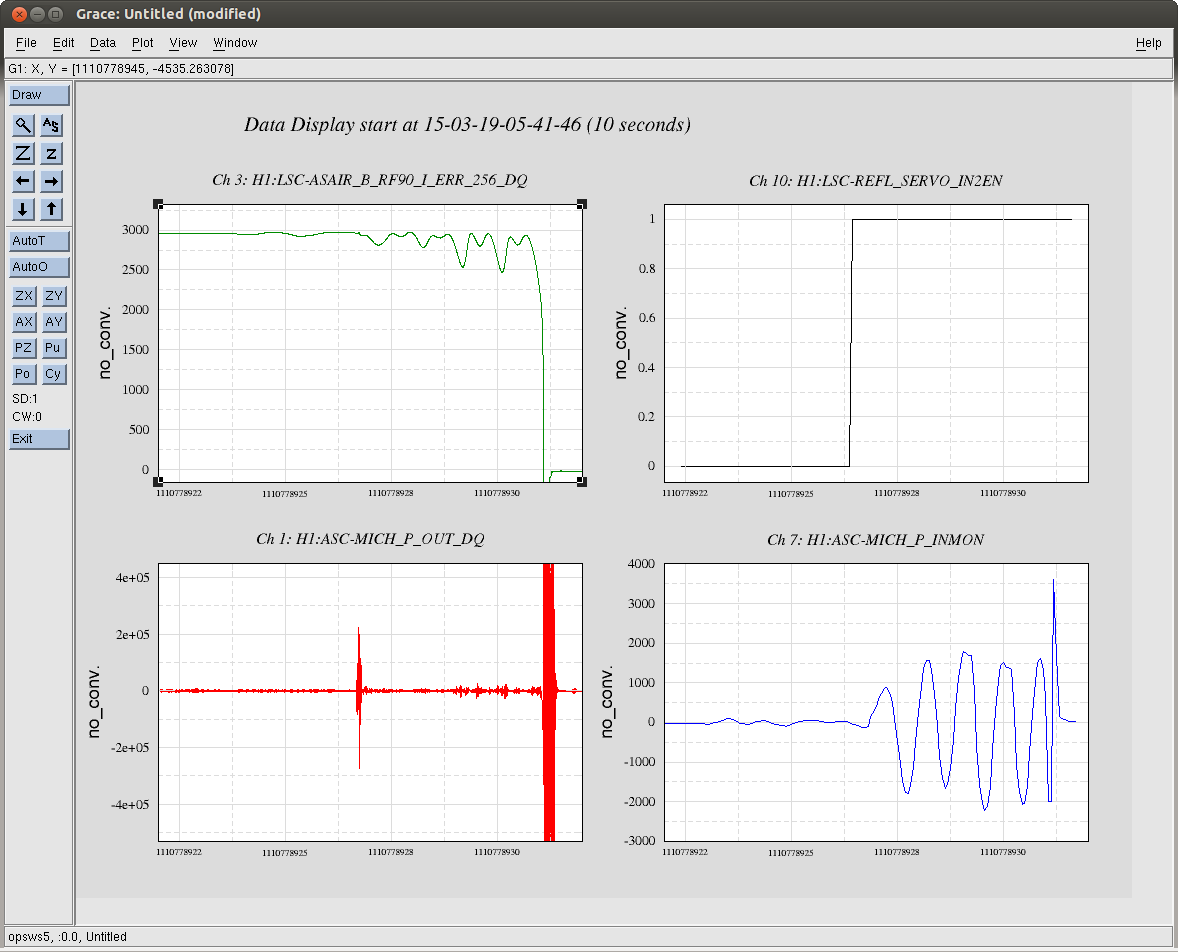
Kiwamu and I investigated the source of BS/SRM saturations, and a few locklosses, in the analog CARM handoff. These saturation events had been variously blamed on the DRMI_ON_POP transition or the ASC loops turning back on, all of which happen in a short window of time. Tonight we discovered it's due to the analog CARM handoff, specifically when input 2 of the REFL CM servo board is enabled with a large (14dB) input gain. (This is the input of REFLAIR9I from the summing board to the CM board.) When the input is enabled there is a big kick to the DRMI optics, and the MICH ASC loops (still engaged in this state) experience a large transient that rings for several seconds due to the inverse BS plant filter. Screenshot of a typical lockloss is attached. We've smoothed out the transition by putting a 10-second sleep in after the REFL_SERVO_IN2EN step. No more locklosses from analog CARM.
-
Violin mode damping is nearly finished. There's one very tricky mode on ETMX that is a very problematic phase.
-
We've continued to use Kiwamu's gains from Monday night to damp the ETMY and ITMX roll modes using AS_A_RF45Q, although I inserted a -100dB gain stage for ETMY to make the value more human readable. Gain for ETMY_M0_DARM_DAMP_R is +40, gain for ITMX_M0_DARM_DAMP_R is +20. These settings have not been propagated to the Guardian yet, I'd like to see if they continue to be robust after we touch up the ITM alignment to increase the recycling gain.
-
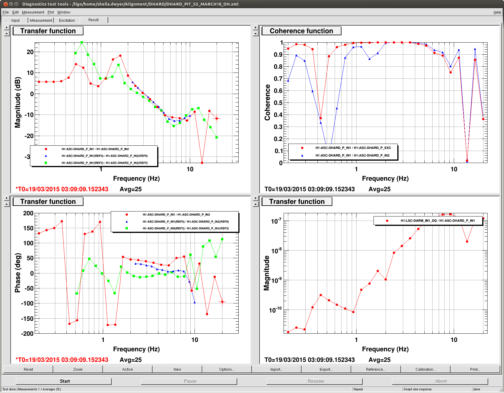
We've been locking at 10W with the new DHARD_P filter. Seems legit.