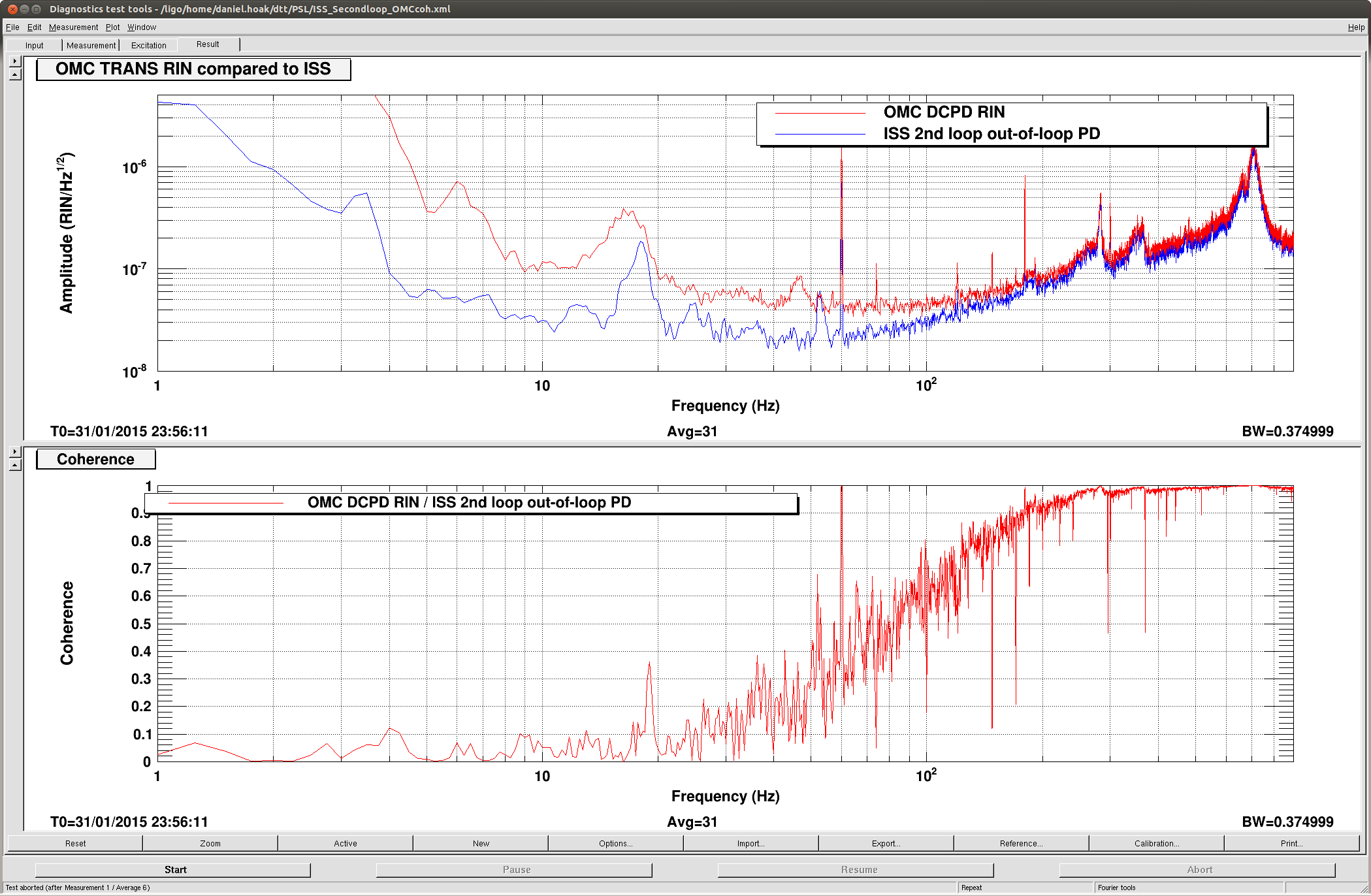
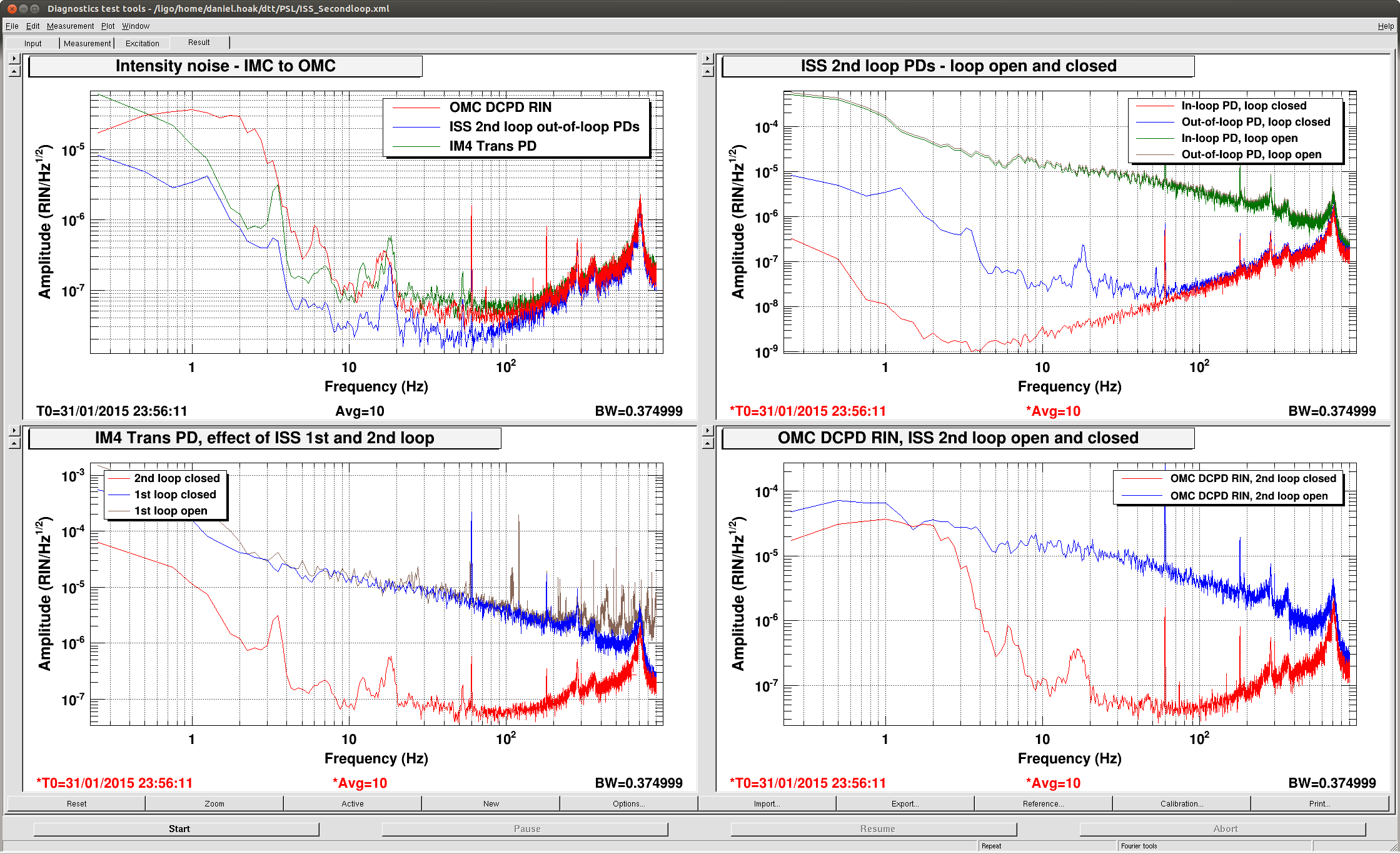
On Saturday we closed the ISS second loop and dither-locked the OMC, with a single bounce from ITMX. In this state we were able to measure the RIN at the OMC DCPDs with the 2nd loop open and closed.
With the ISS second loop closed, the relative intensity noise at the OMC DCPDs at 100Hz is about 5x10^-8 / rt[Hz]. Above 100Hz, the OMC DCPD RIN is limited by intensity noise; below 100Hz the noise is from something else. See the first plot. The OMC DCPD sum was ~14mA at the time of the measurement, and the shot noise RIN should be 5x10^-9/rt[Hz], well below the measured noise floor.
Compared to Gabriele's measurement from November, the noise with the ISS 2nd loop open is ~10x worse, compare the second plot, upper right, to his third plot, lower right & left. Is the excess noise due to jitter into the IMC? We did not take the time to fiddle with the IMC WFS offsets. Gabriele measured 10^-8 RIN/rt[Hz] at 100Hz with the 2nd loop closed, but we measure 3x10^-8 /rt[Hz], so above 100Hz we may be limited by the gain of the ISS 2nd loop. If this is the case, then improving the RIN out of the IMC could reduce the intensity noise at the AS port.
In the second plot, we compare some signals with the ISS loops open and closed. The second loop suppresses the noise at the OMC DCPDs by about a factor of 100 (lower right plot). Note that in the lower left plot, of the RIN observed by the IM4 trans PD, the ISS first loop only improves the noise at high frequency.
There is a peak in the intensity noise at 700Hz that is not suppressed by the second loop. This also seems to be ~10x worse than what Gabriele measured in November. It's not clear where the peak is coming from, it's seen by the IMC WFS (see third plot), but not by any PEM or IMC length channels that I can find. This peak is broad enough that it may cause trouble with the OMC ASC dither lines. (L1's dither frequencies are around 550-650Hz.)
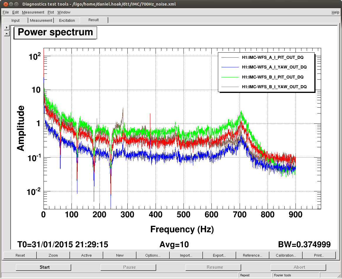
You can easily get a factor ~10 more noise in transmission of the IMC, if the alignment is not good, see for example log 14301. This is beam jitter converted by the IMC into intensity noise.