Summary:
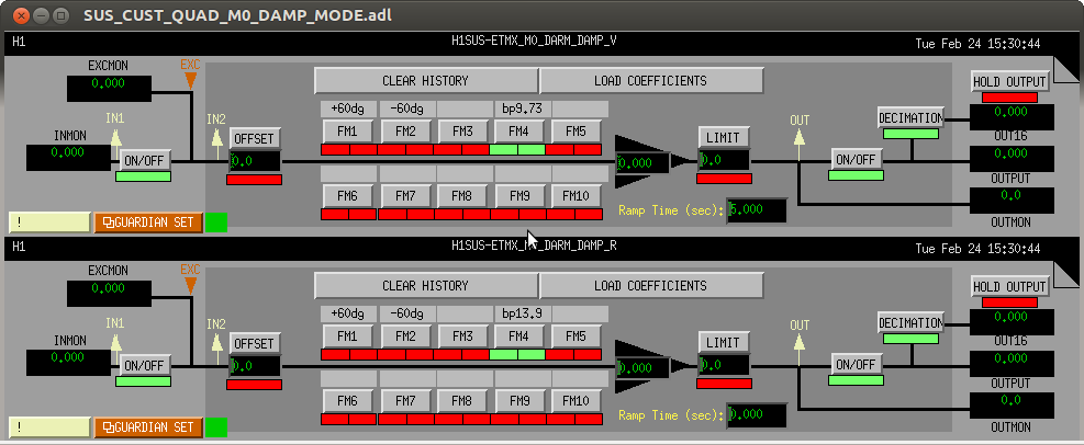
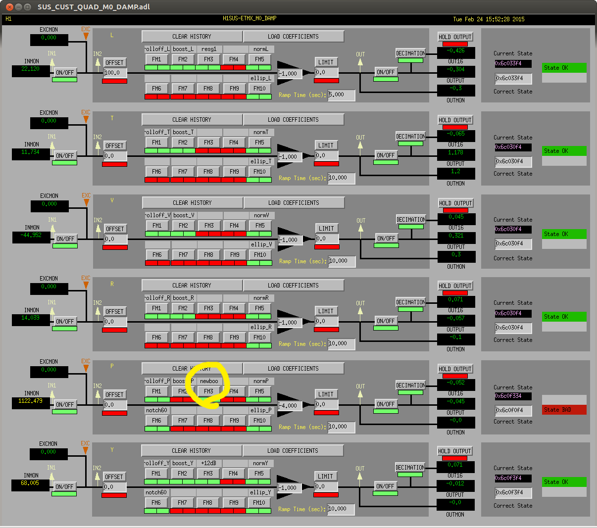
A new ETMX M0 P damping filter was made, together with a new damping gain (first and second attachment), to make the L1 length to L3 PIT coupling at 0.5Hz smaller.
This makes the coupling at 0.5Hz smaller by 8dB or so, but it increases the coupling at 5.5Hz and 3.5Hz, and overall it seems to give us about a factor of 1.5 or so of reduction on average.
This was only done to ETMX, and moving to the new damping of course affects the WFS, so I left it with the old configuration.
Details:
(All of the measurements were made without oplev damping.)
People say that a higher BW WFS is necessary during CARM reduction, and that oplev damping is necessary for ALS. The problem could be a large (and noisy) length drive coupled to the angle.
Instead of optimizing the top mass damping for making test mass as quiet as possible without drive, I tried to minimize the coupling from L1 length drive to L3 PIT. I injected a [0.2Hz, 0.8Hz] uniform noise to L1 Lock L filter so the L1 coil drive does not exceed +-5000 counts or so peak to peak (otherwise the resulting PIT motion becomes too large so the OPLEV starts to miss an entire quadrant).
I started by simply making the gain of the existing filter up or down. This didn't do much, as the steep phase slope of 0.5Hz boost filter makes it such that when you gain something at 0.5Hz you quickly loose at 0.4Hz and 0.55Hz by gain peaking.
After some trial and error I ended up with a broader version of the original filter (second attachment).
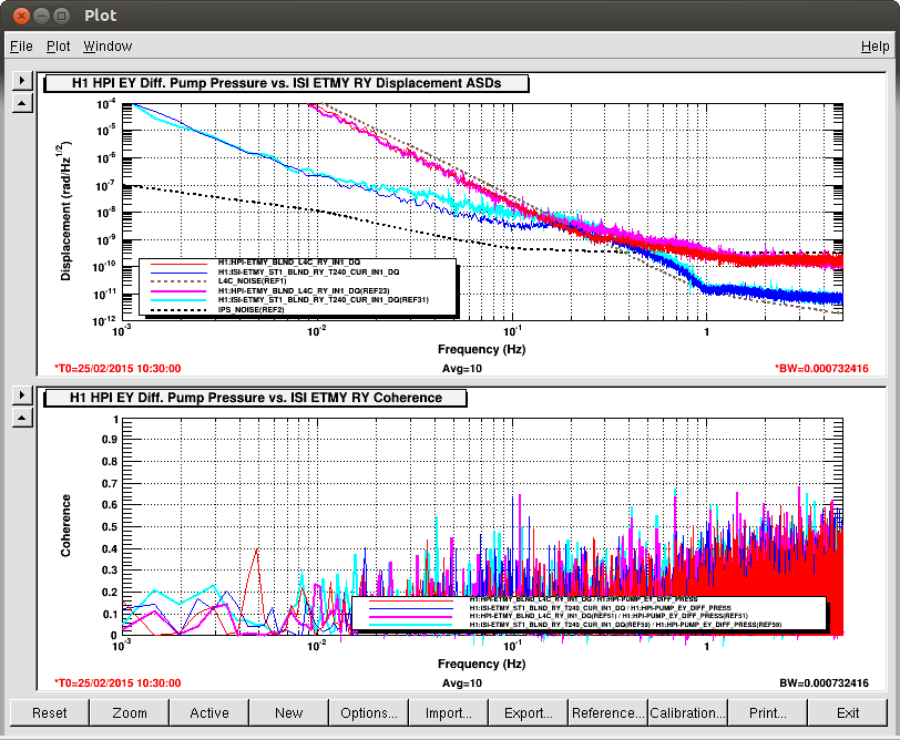
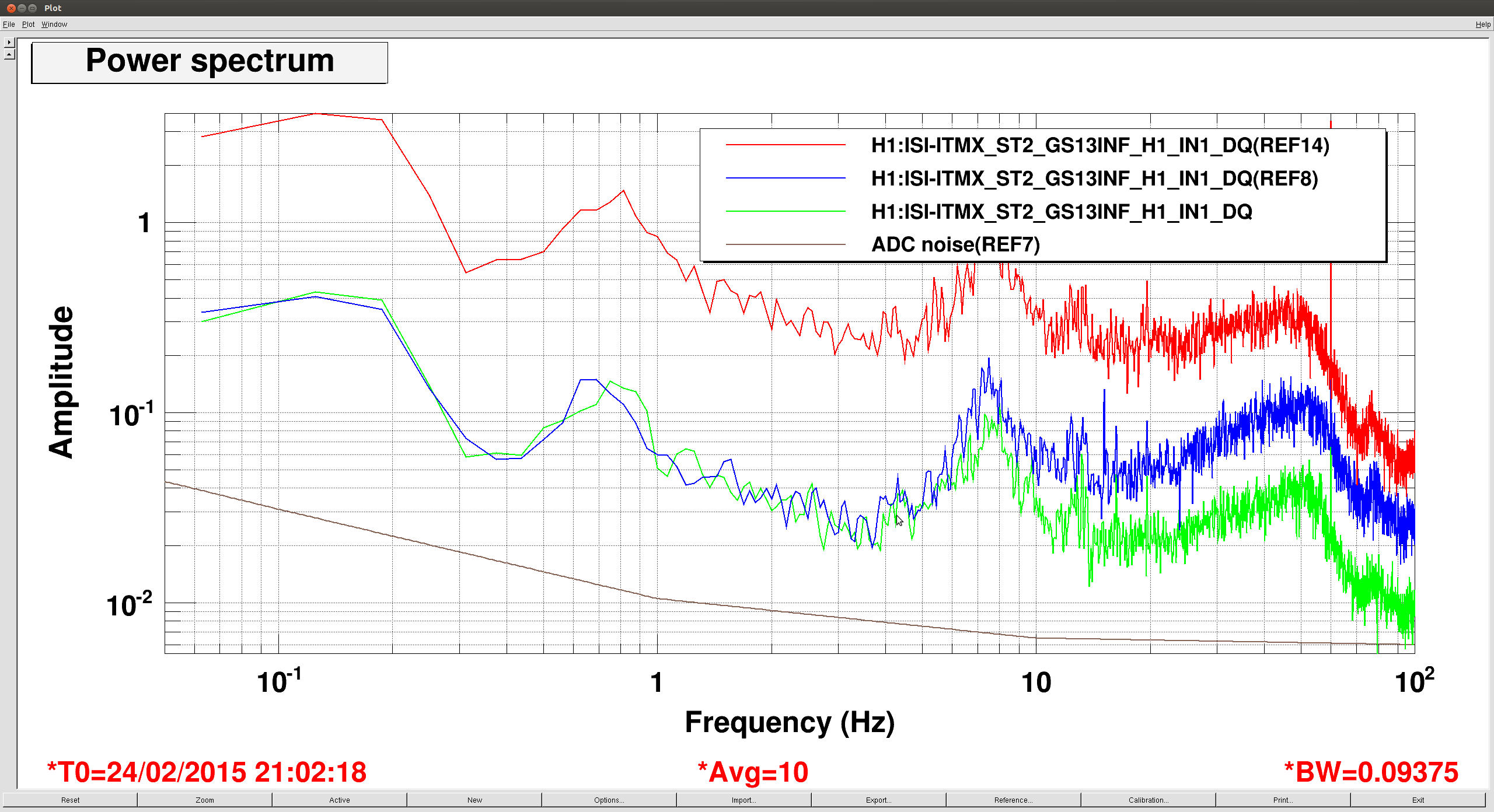
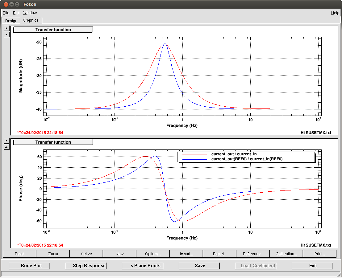
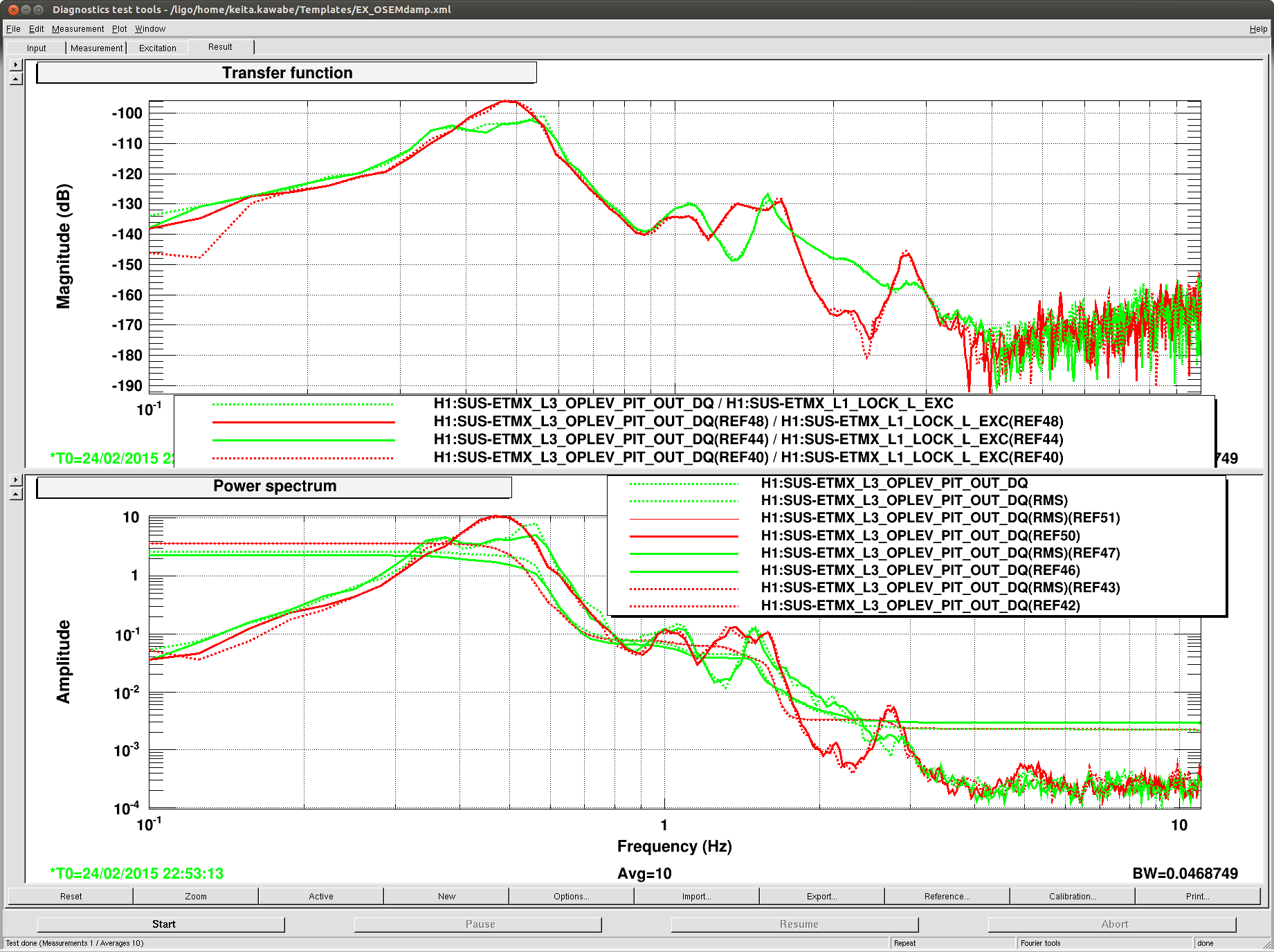
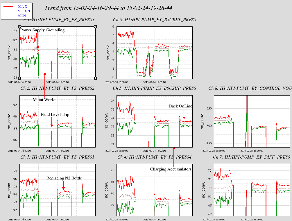
The third attachment shows my old/new/old/new test (Old = Red traces, FM2 on, FM3 off, gain = -1. New = green traces, FM2 off, FM3 on, gain=-4).
The top panel shows the transfer function from the L1 length drive to the oplev PIT, and the bottom panel is the oplev PIT spectrum with the length drive into L1. As you see the TF shows the reduction at 0.5Hz but some increase due to gain peaking at higher and lower frequency, and the overall RMS reduction in the TM angle due to the length drive is about a factor of 1.5.
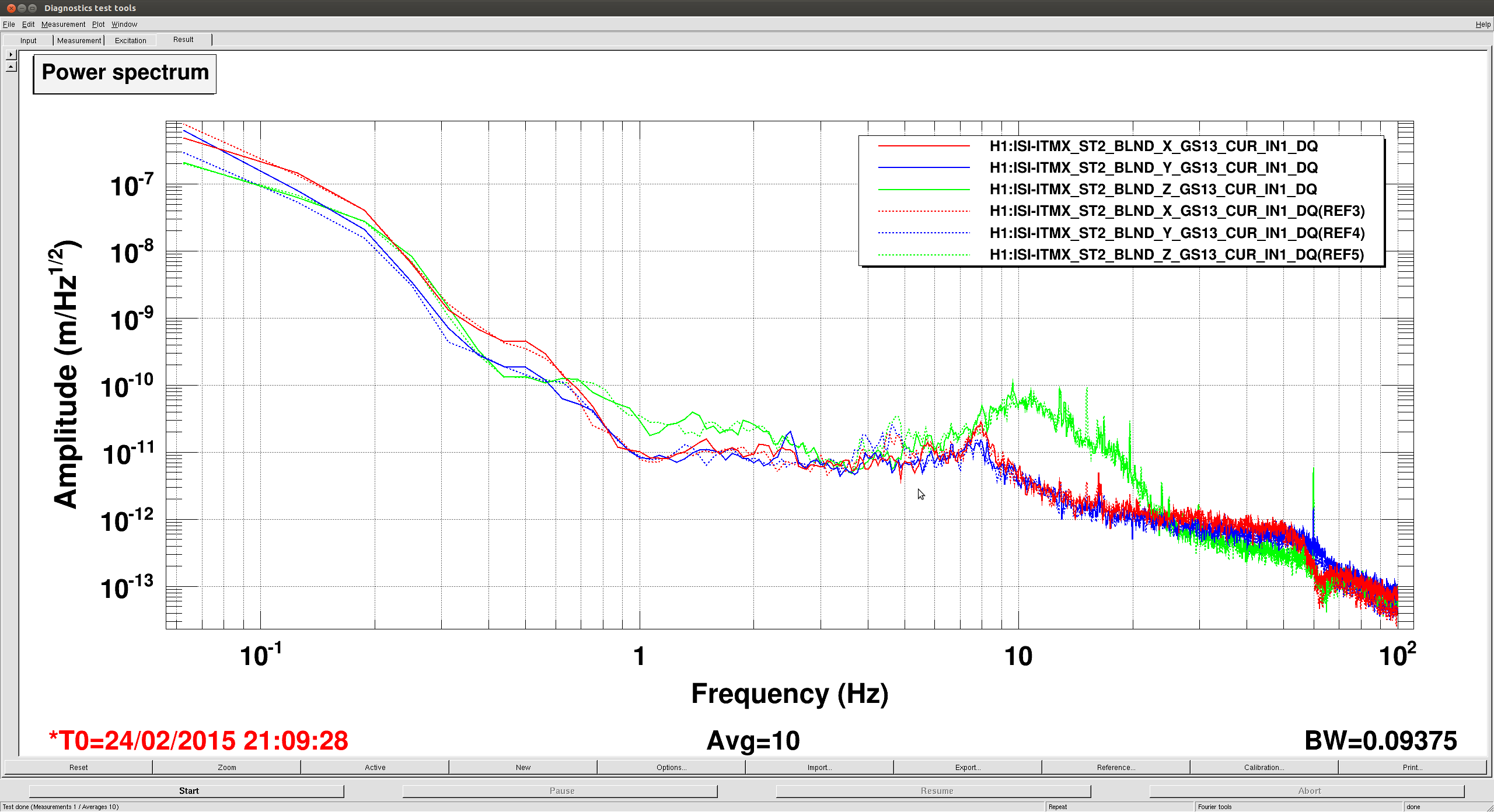
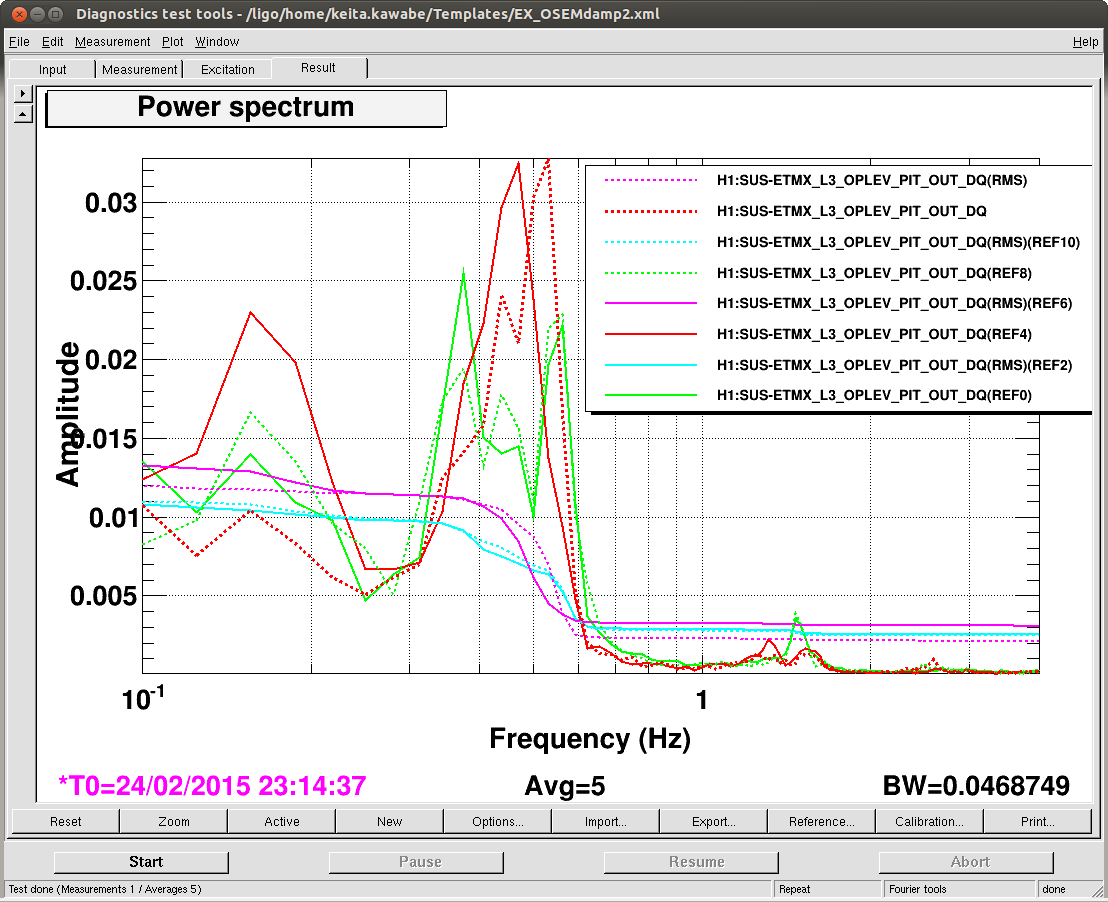
A reduction in the RMS of the test mass angle when we're not driving L1 length is not large, but it is reduced by a small amount (4th attachment, red old, green new).
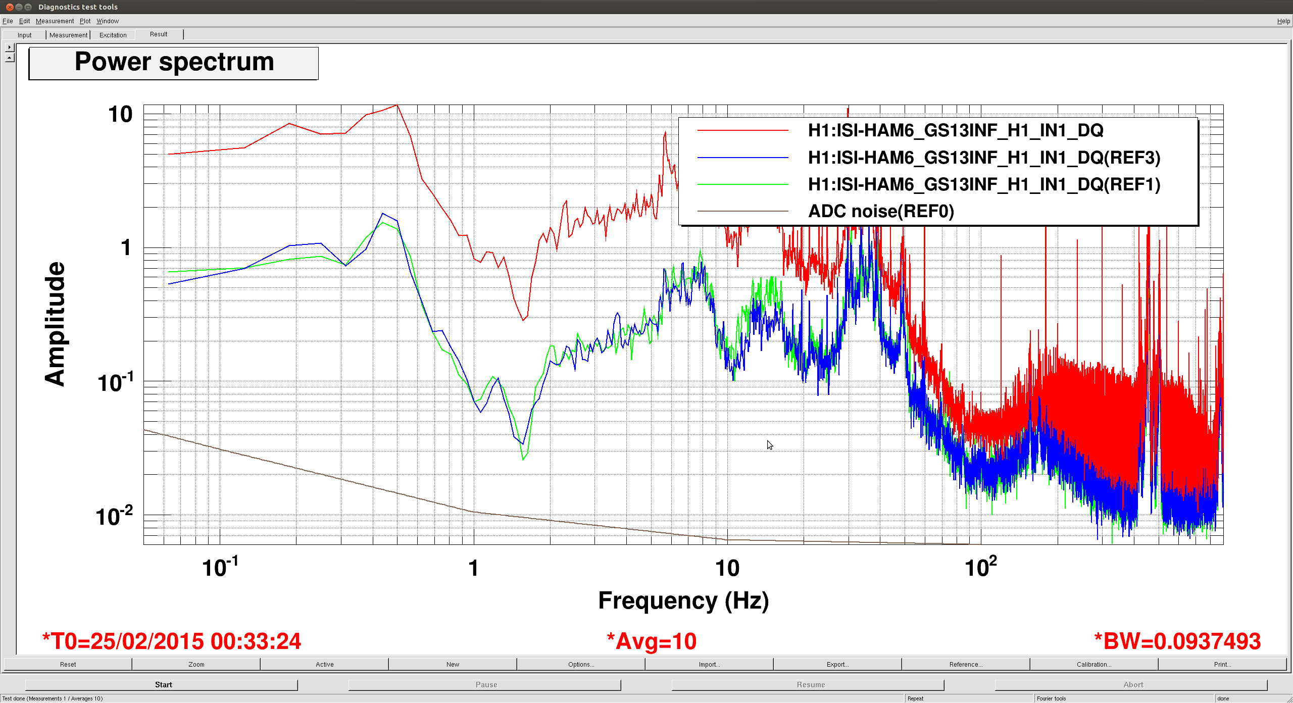
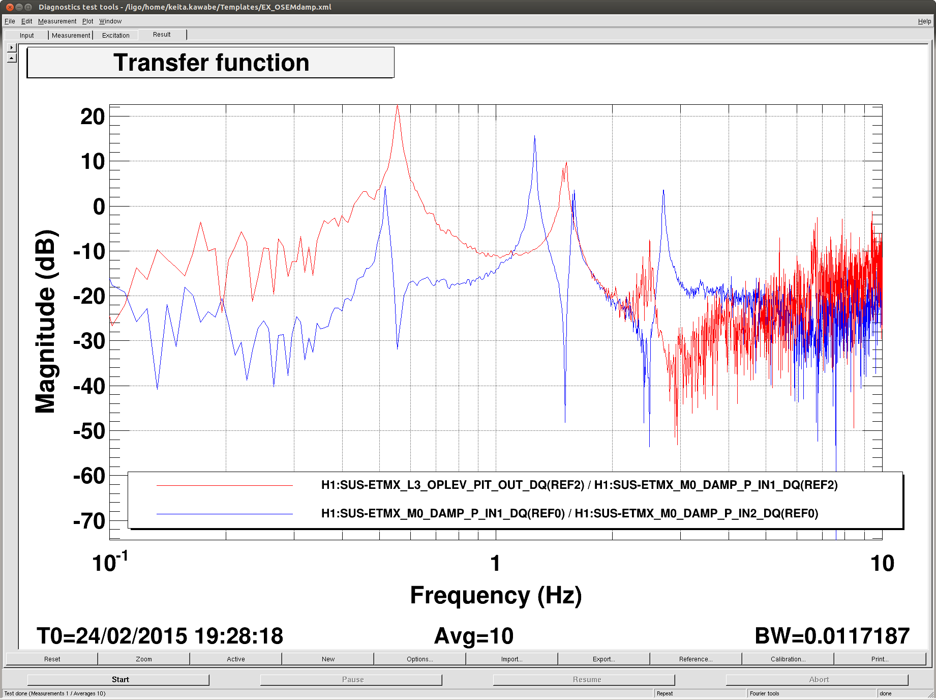
It would be very difficult to reduce the l2p coupling at 0.55Hz just by the top mass local damping, as there's a sharp dip in the OLTF of the top mass damping that should come from the lower suspension structure (5th attachment, blue=OLTF, red = top OSEM P to oplev P, both measured while driving M0 DAMP_P_EXC). A gain of -3 or so with the new filter to make the damping less aggressive, combined with some other means of decoupling, seems necessary to obtain an advanced awesomeness.