Summary:
Now that we have decent arm buildup, we can look at the baffle PDs with real S/N.
Y arm looks lossier than X, but we knew that.
The scattering seems to have distinct spatial pattern that is not rotationally symmetric around the mirror center axis. Probably because of localized scattering bodies.
The scattering pattern moves in time. Probably because of alignment fluctuation.
Wise people might want to help disentangling these and tell where the localized scattering bodies are and how much they are scattering.
Details:
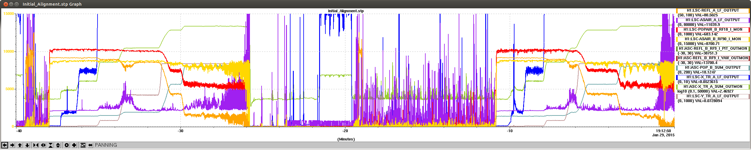
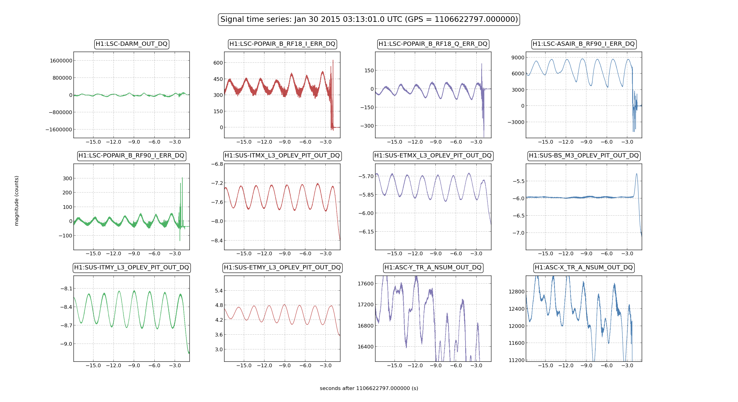
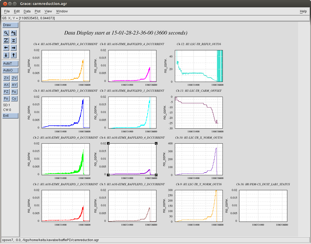
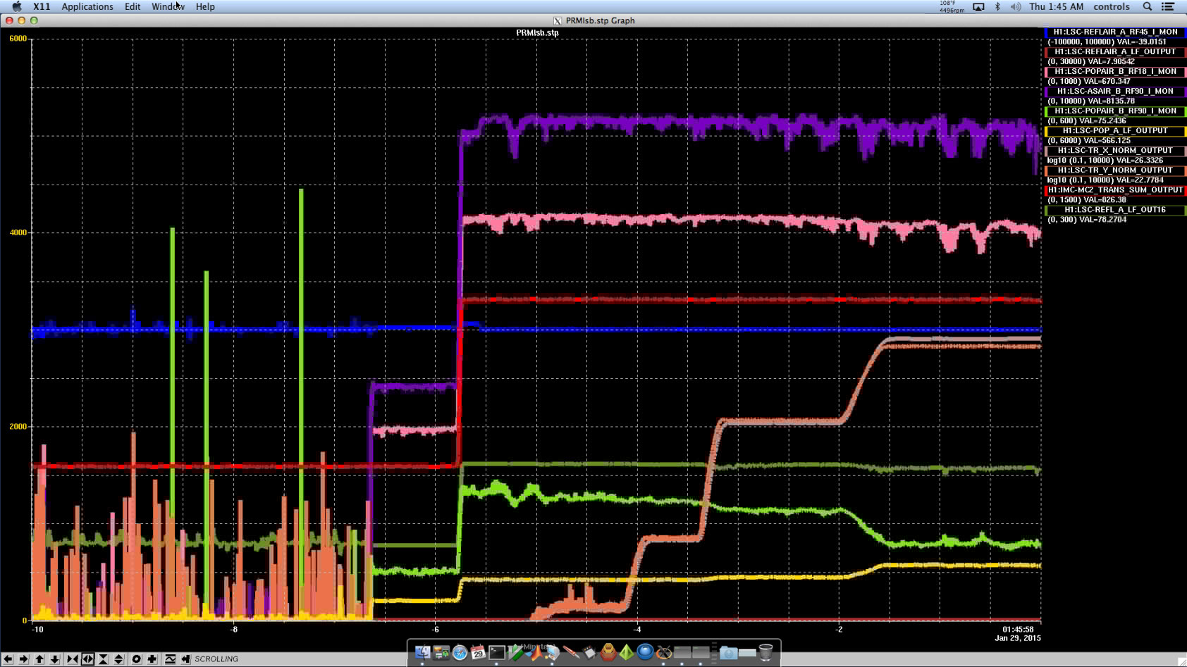
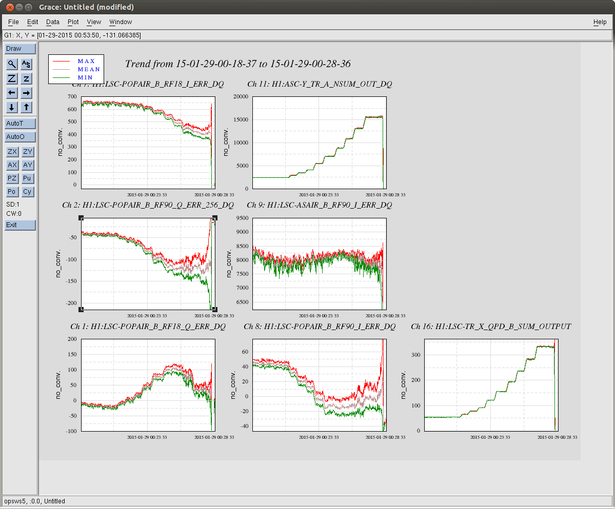
First attachment shows 30pm CARM offset lock stretch from yesterday. At the end of the lock, TR_CARM offset reached 25, which translates to about 30pm.
If you just mask everything out except this 30pm period, after subtracting dark offset (obtained after lock loss) we obtain the following DC current table:
|
|
PD1 mean (std) [uA] |
PD4 mean (std) [uA] |
E1+E4+I1+I4 |
|
EX |
8.4 (0.3) |
2.9 (0.1) |
36.5 (0.9) |
|
IX |
17.5 (0.3) |
7.7 (0.4) |
|
EY |
8.0 (0.5) |
10.9 (1.4) |
47.8 (1.9) |
|
IY |
16.5 (0.7) |
12.3 (0.4) |
The first thing you'll notice is that the Y arm seems to be somewhat lossier than X, which we already knew.
The second thing is that the scattering is not rotationally symmetric around the mirror center axis. If it is, PD1 and PD4 on the same baffle will see the same power. In reality, in X arm, IX PD1 receives the biggest power (17.5), EX PD4 the smallest (2.9), and the remaining two are both about half of the biggest guy. In Y arm, ITM baffle receives more power than ETM, and the biggest/smallest are much closer than X.
There should be some localized scattering source.
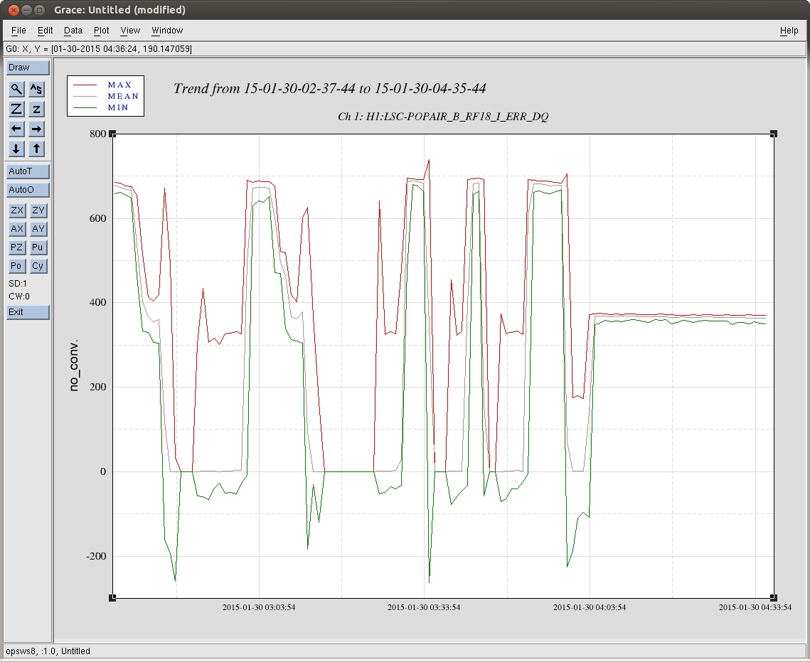
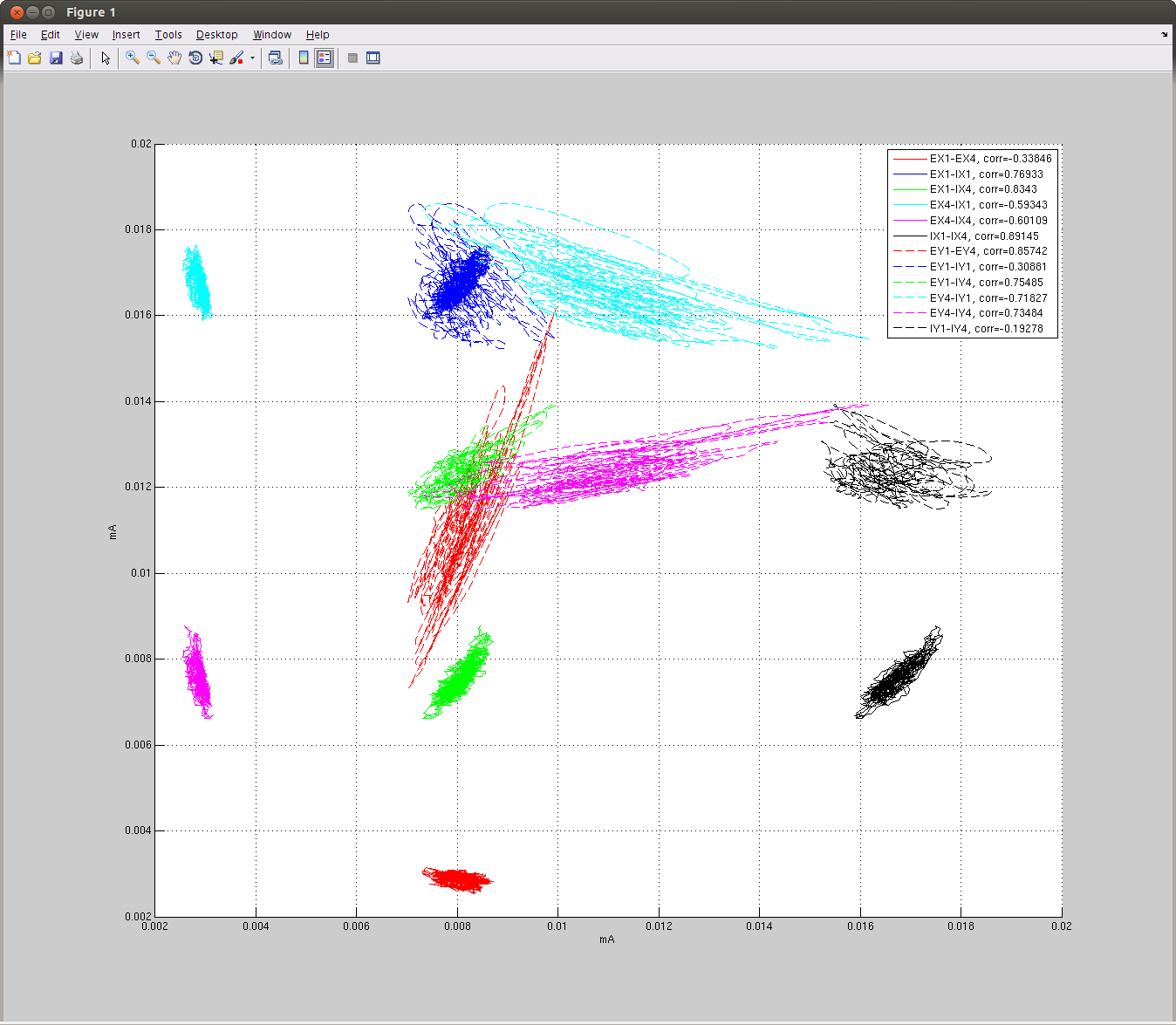
The second attachment is a scatter plot of various PD pairs. This in itself is pretty useless for anything except to show you that the fluctuations in some PD pairs are correlated, some positively and others negatively. It's also apparent that Y arm is moving much more than X. I didn't plot correlation between different arms because there's almost none.
Anyway, the scattering pattern is moving, dumping more or less power on these PDs.
I cannot disentangle these but wise people might be able to.