Alexa, Elli, Sheila, Rana, Evan
Today we worked some more to make the sqrt(TRX+TRY) handoff more robust.
Now we can pretty reliably complete the transition by hand. We are working on implementing the transition in the guardian.
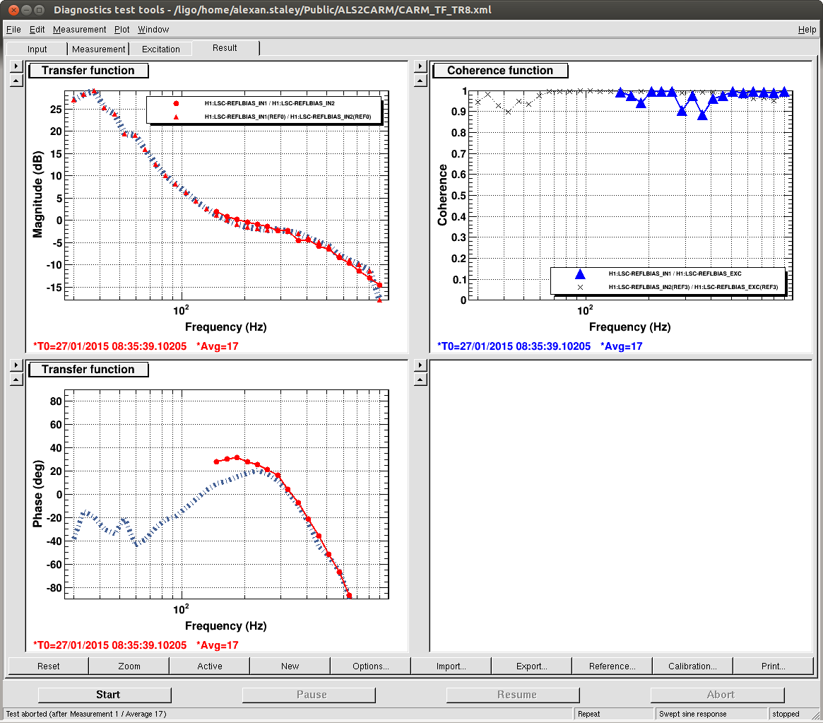
We have tried to reduce the CARM offset while locked on sqrt(TRX+TRY), but we cannot seem to get beyond 2 or 3 times the single-arm power without blowing the lock. The next step is to go through the CARM reduction sequence more carefully and characterize the OLTF of the CARM loop in this state.
Gain redistribution
As discussed in LHO#16252 et seq., we suspect that the common-mode board has gain-dependent offsets. If this is true, it explains why the interferometer can be knocked out of lock while ramping down or turning off ALS COMM.
To boost the CARM loop's immunity to these offsets, we redistributed gains as follows:
-
The gain of the ALS COMM input on the common-mode board was increased from −4 dB to +16 dB (
LSC-REFL_SERVO_IN2GAIN). Correspondingly, the gain on the AO into the IMC board was reduced from +16 dB to −4 dB (IMC-REFL_SERVO_IN2GAIN).
-
The input matrix gain for the slow path out of the IMC board (going into the digital CARM control) was decreased from 1 to 0.1 (LSC-PD_DOF_MTRX_5_26).
-
The digital gain for sqrt(TRX+TRY) was increased by a factor of 10 (
LSC-REFLBIAS_GAIN was increased from 0.8 to 8).
Even with these changes, success is not guaranteed. The gain steps can be heard very clearly when listening to LSC-CARM_IN1, and turning off ALS COMM on the summing board will blow the lock about half the time. We can get better results by using the gain slider on the common-mode board, but we can still hear the gain steps.
Modified handoff procedure
-
In
LSC-REFLBIAS, we engage FM3 (1 Hz pole, 40 Hz zero) and FM9 (1.6 Hz pole, 40 Hz zero). The gain is 8 ct/ct.
-
In
LSC-TR_CARM, we set the offset to −0.5 ct.
-
We engage the sqrt(TRX+TRY) path on the common-mode board.
-
We engage
LSC-REFL_DC_BIAS with a gain of 30 ct/ct.
-
Once the buildup has stabilized, we turn on FM6 (0 Hz pole, 1 Hz zero). Then we turn on FM4, which undoes FM3. Then we ramp the gain of
LSC-REFL_DC_BIAS to 50 ct/ct.
-
We ramp down ALS COMM using the common-mode board input gain slider. Then we turn off this input on the common-mode board.
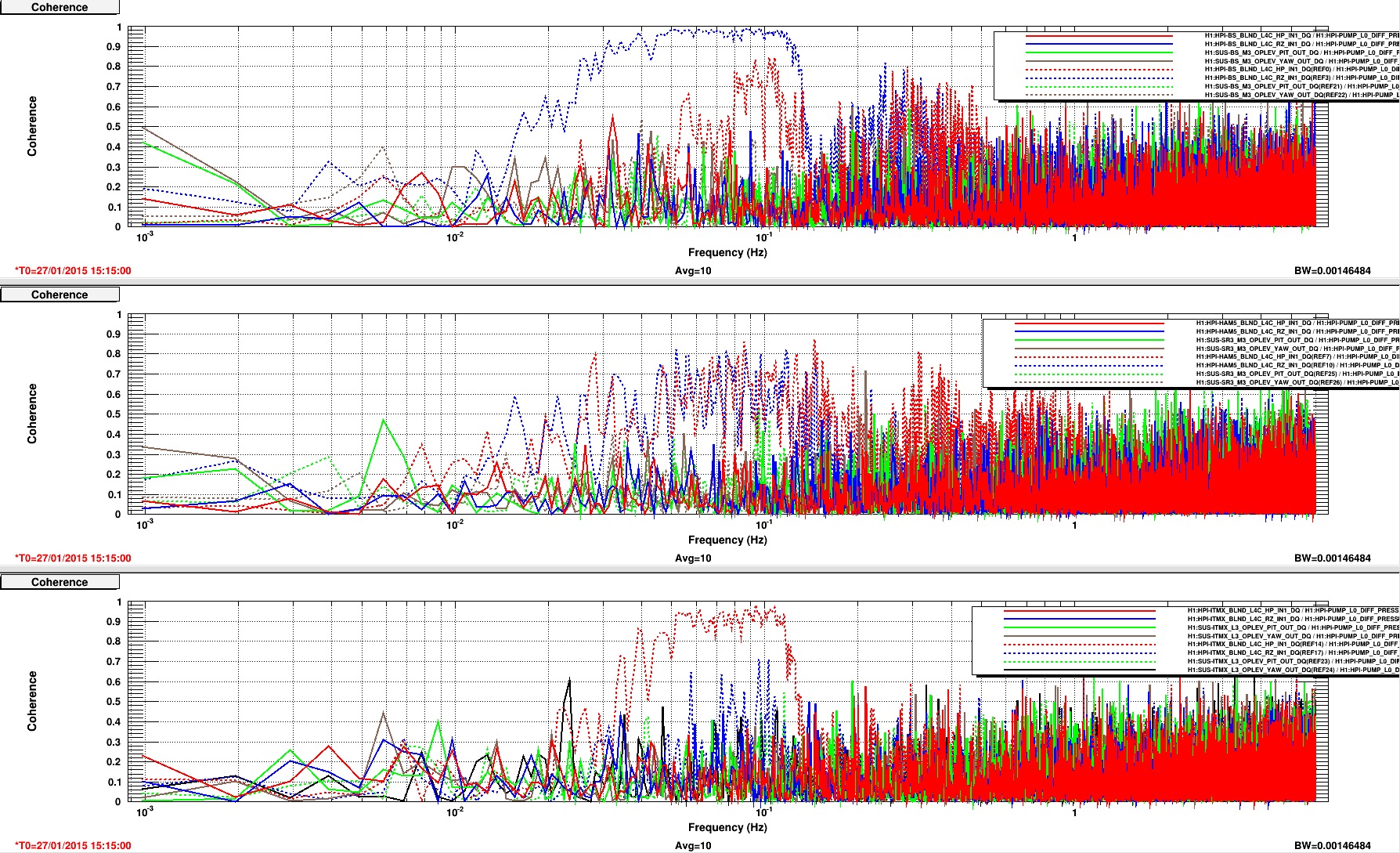
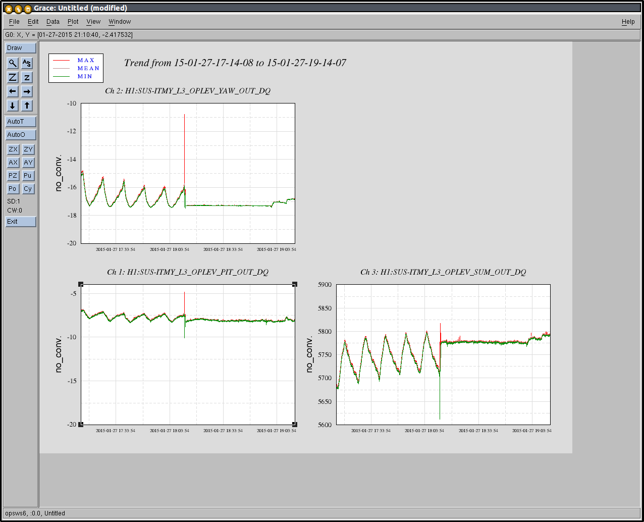
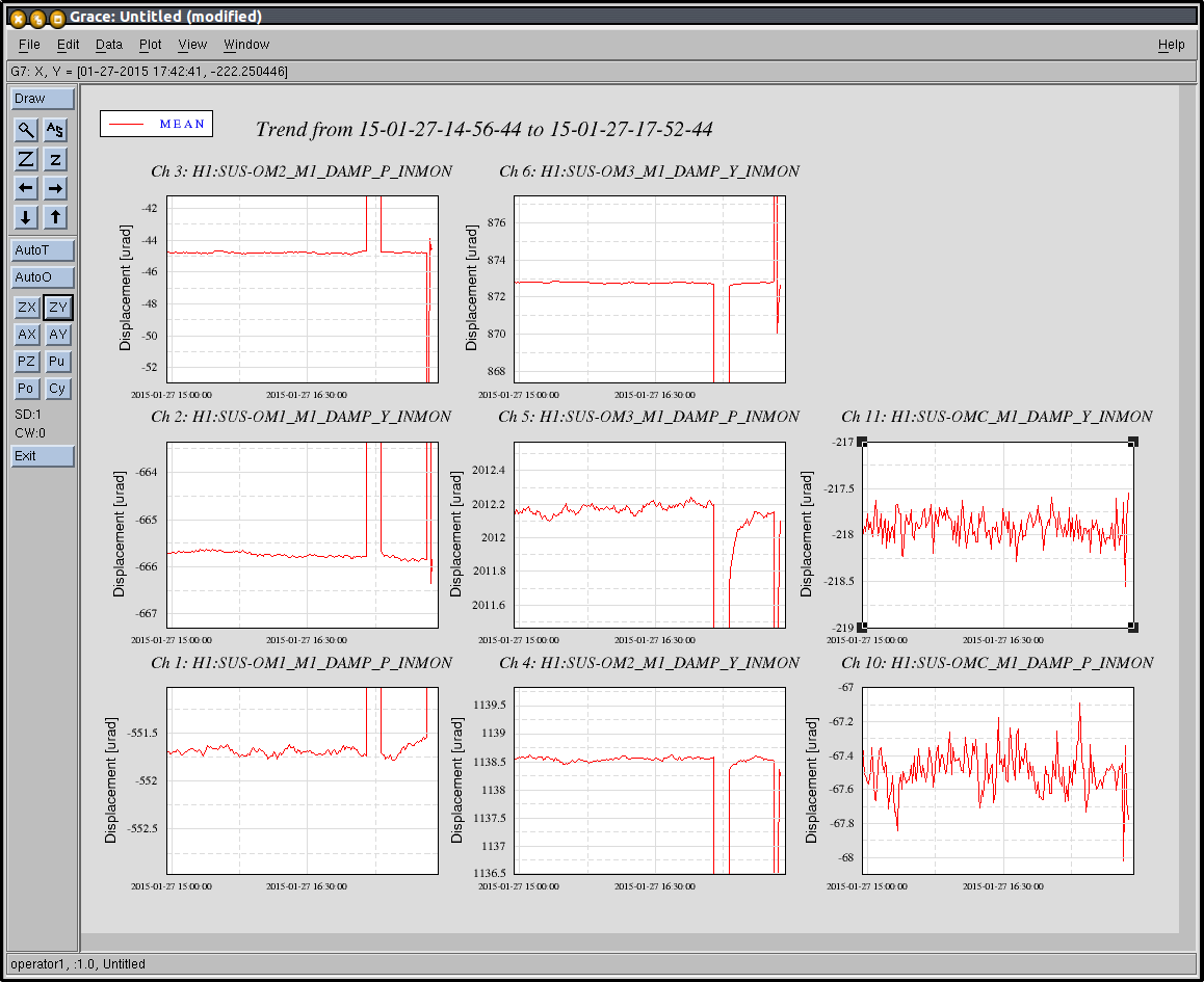
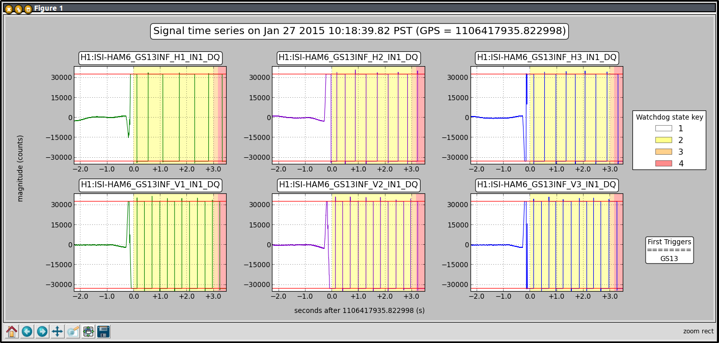
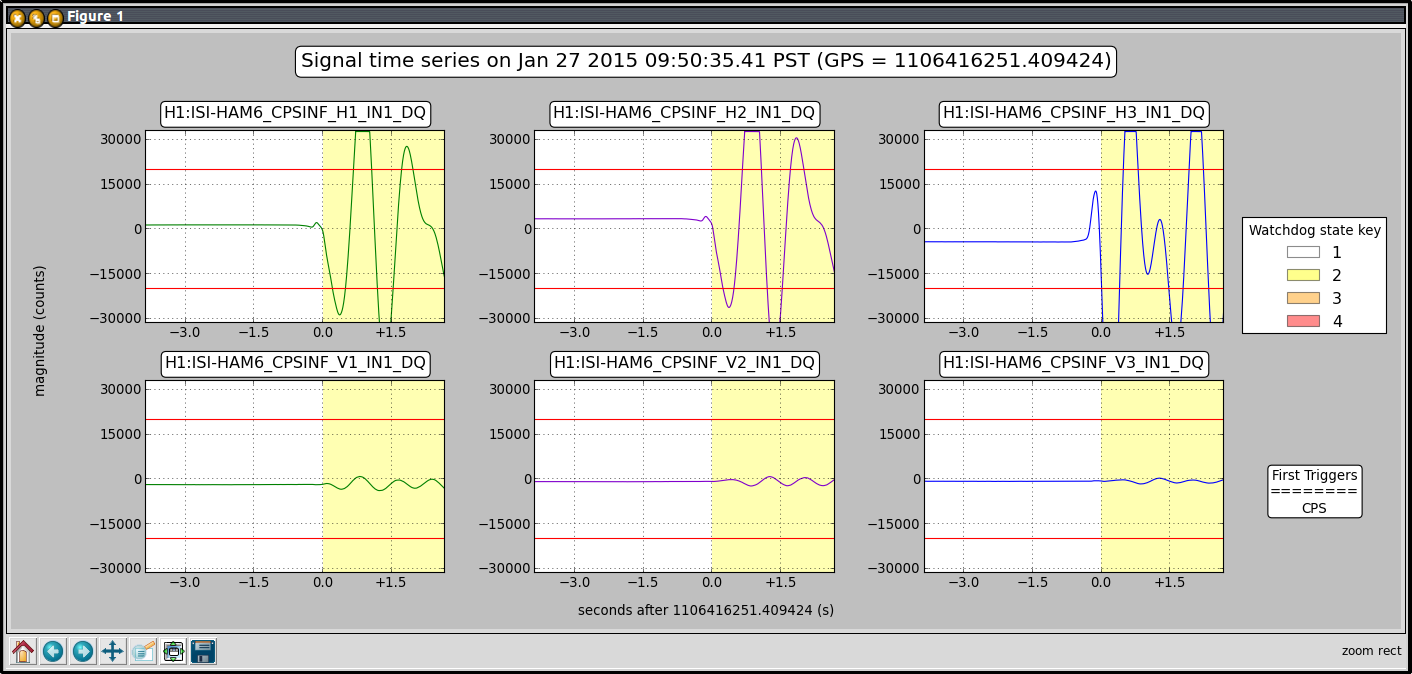
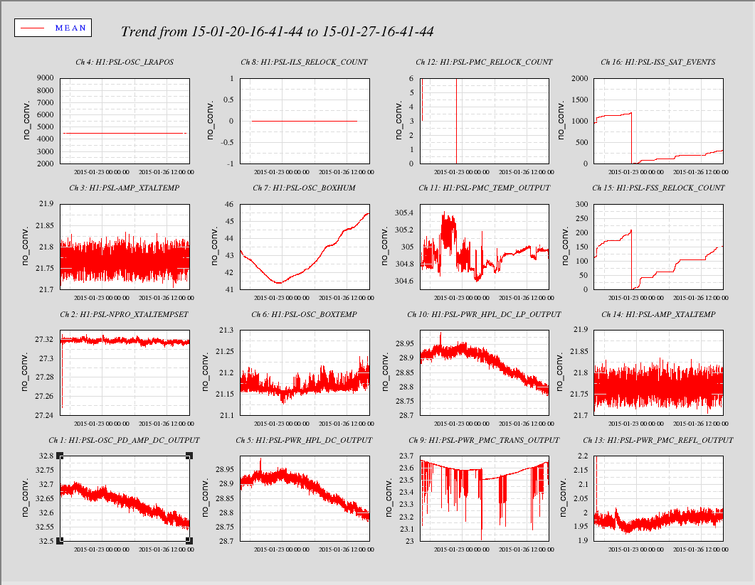
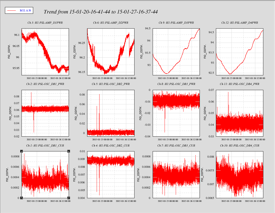
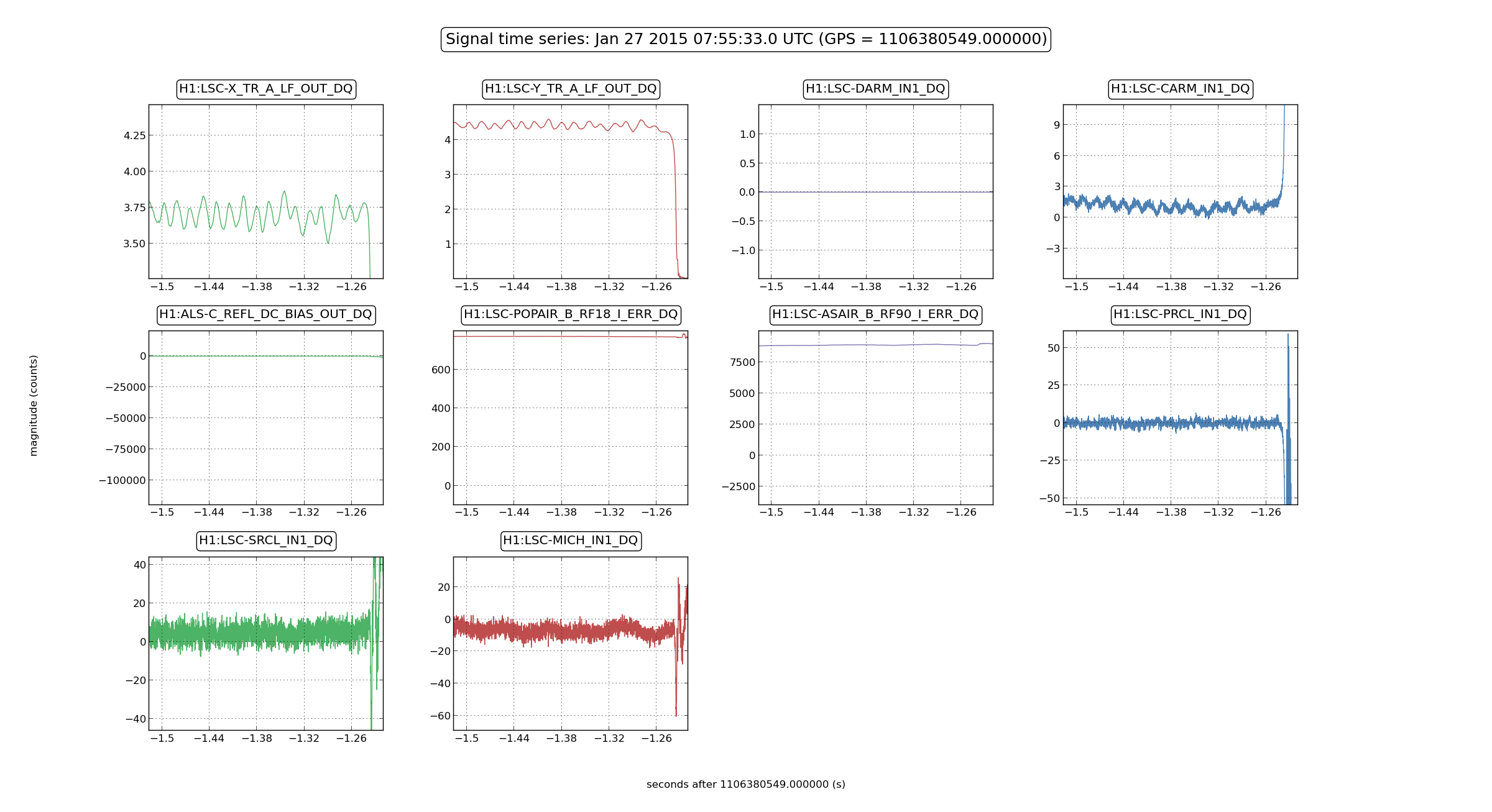
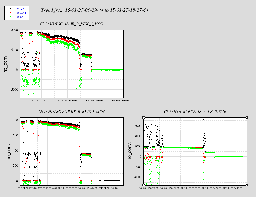
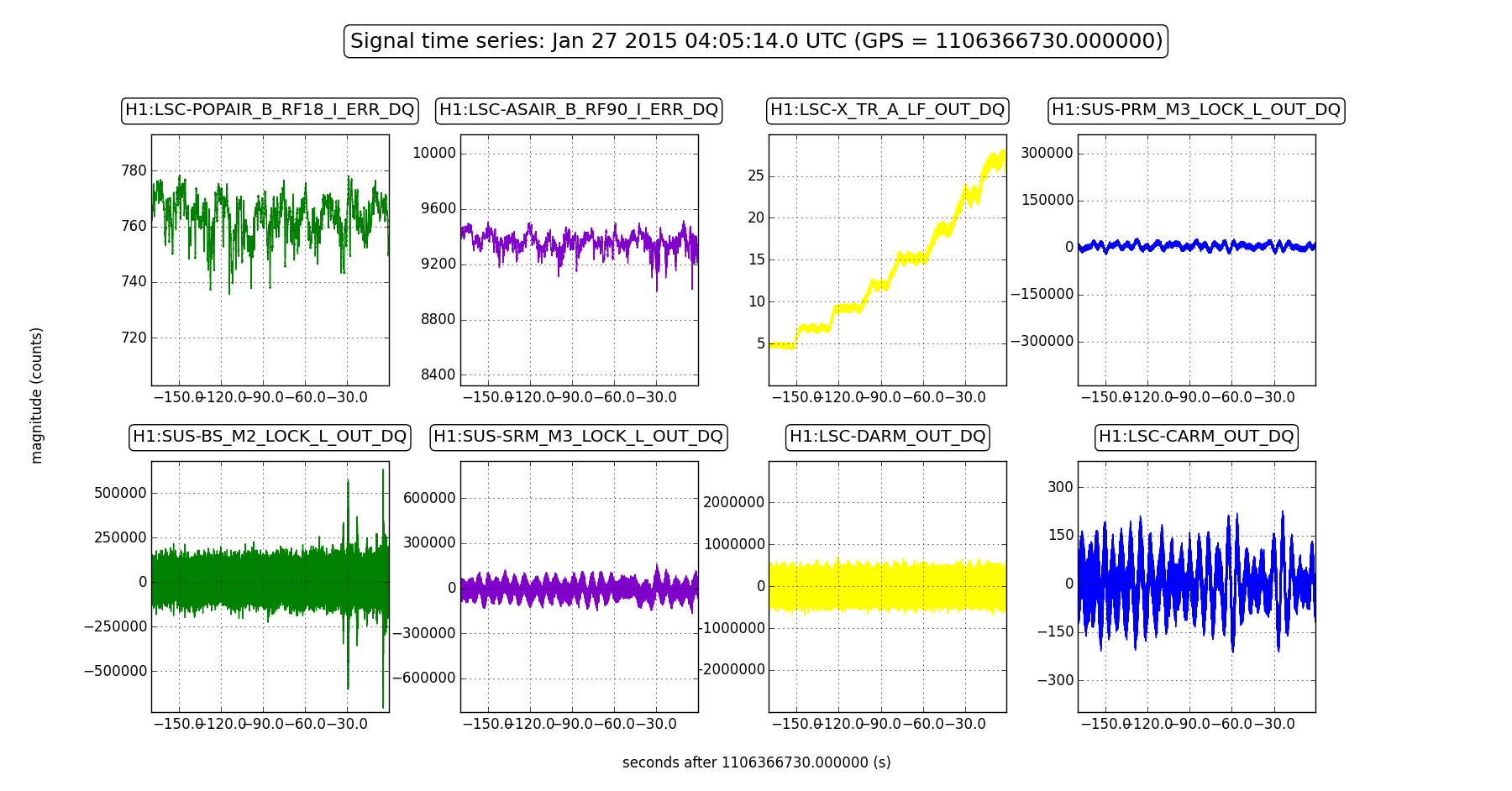
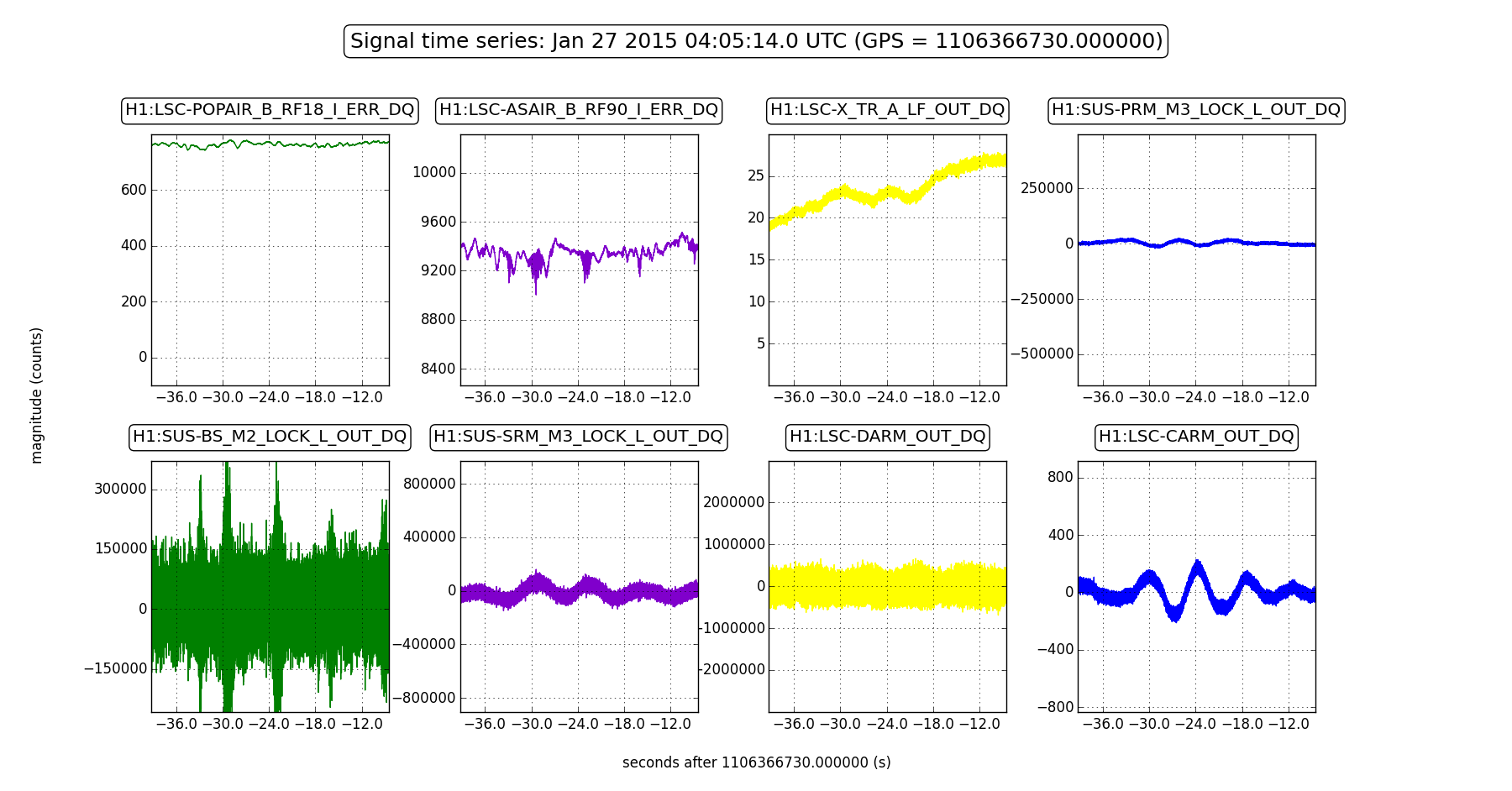
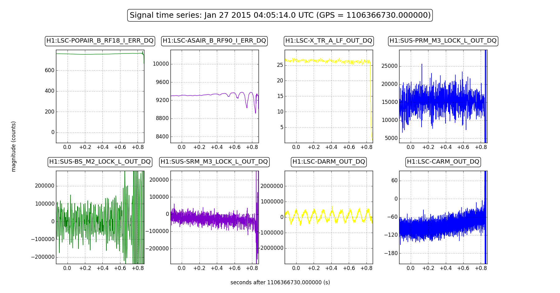
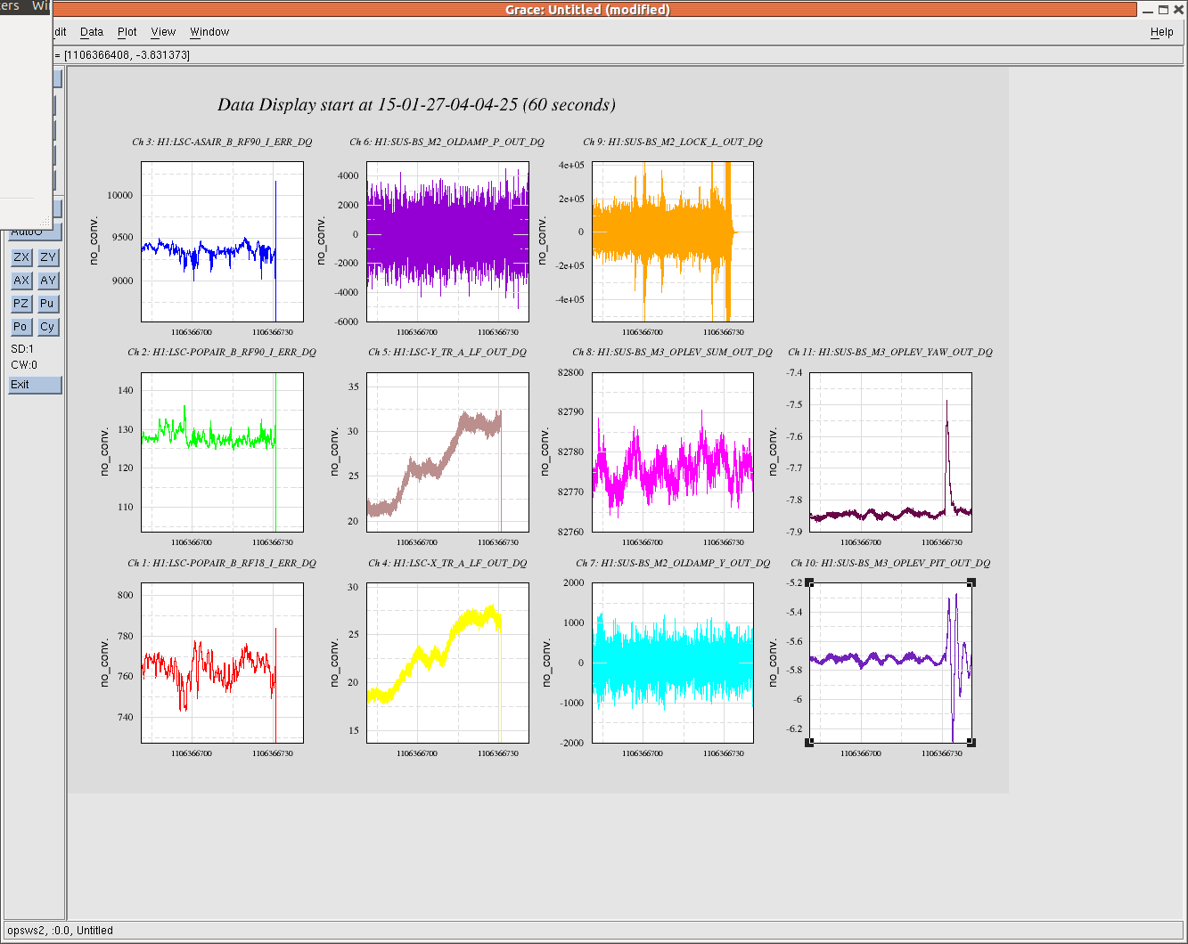
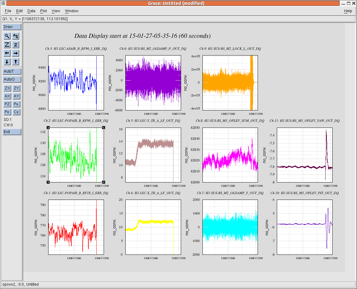
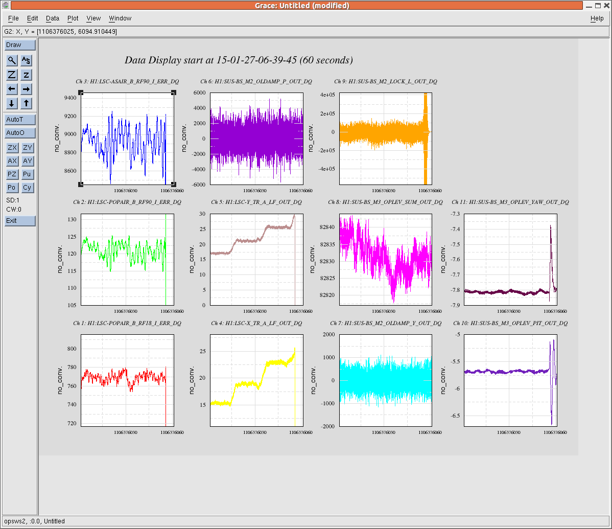
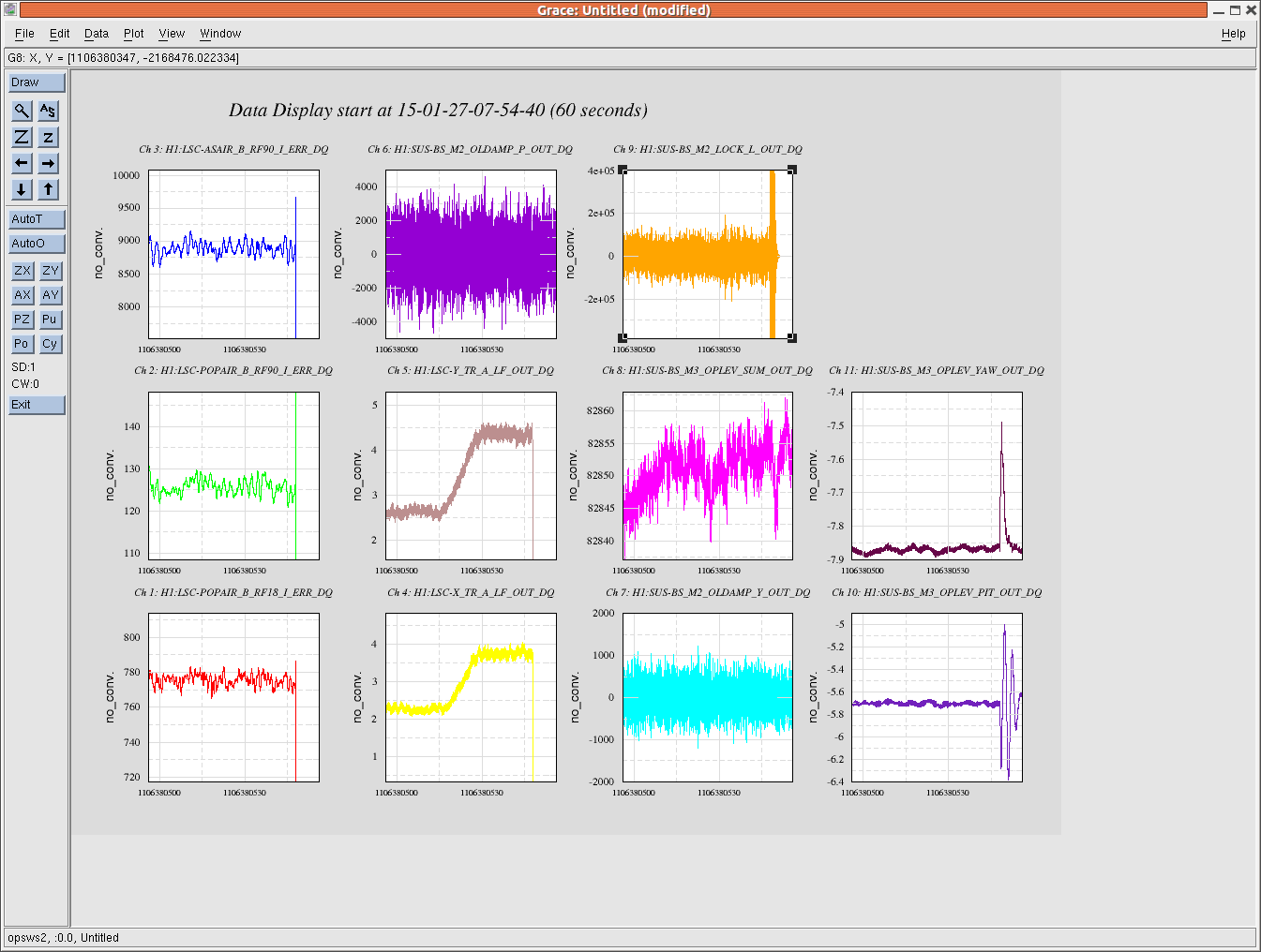
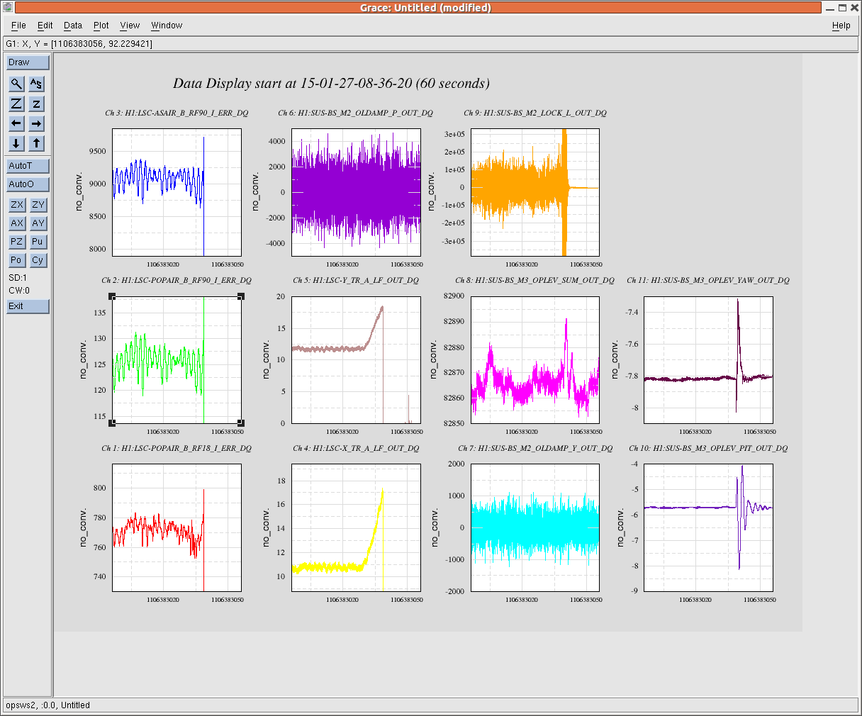
A lockloss plot is attached for an unexplained lock loss during the CARM offset reduction after handing off to sqrt(TRX+TRY). Other lock loss times, all 2015-01-27 UTC: 03:56:53, 04:05:25, 05:36:16, 06:40:59, 07:56:02, 08:37:20. The last four are during CARM offset reduction after the handoff is complete.
For a sqrt(TRX+TRY) offset of −1.5 ct, the gain we need for REFL_DC_BIAS is 50 ct/ct. Our OLTF looks good here. However, when we reach an offset of −2, we seem to lose lock, even though there is no obvious nastiness in the CARM spectrum.
Mystery
Today, locking DRMI without arms was pretty painless. In contrast, DRMI+arms lock acquisition was very, very slow for most of the morning and afternoon. After about 5pm local, it became painless as well. This may have been correlated with our changing the trigger settings to be twice as high with arms (compared to no arms), since the POP18 buildup is twice as high. But we haven't investigated this systematically.
