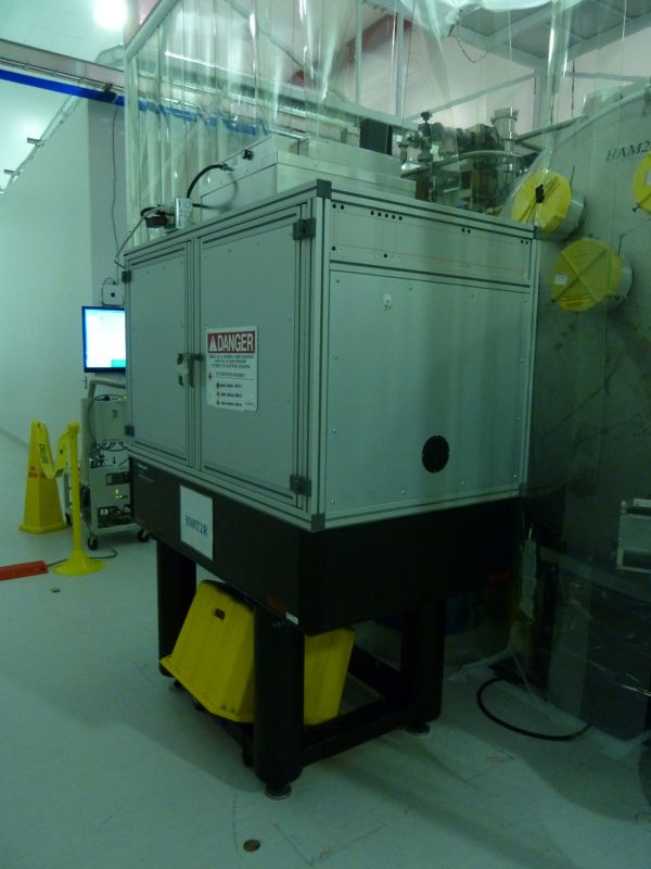
Sheila, Alexa
After spending the afternoon on the arm locking, we spent some time looking at the COMM handoff. (Plots coming in the morning...)
I am leaving the arm cavity locking, PRM parked and ITMY misalinged, and the alingment servos off.
I have started to study ETMX performance: - The figure in page 1 shows the ISI motion in the controls configuration that has been used for a week and half or so (Level 2 controls with TCrappy blend filters). Looks like the X signal has been significantly dominated by tilt (see good match of pink and green curves). - page 2 shows the optical lever pitch motion, it illustrates that most of the RMS is in the .6 to .4 Hz band (nothing new there) - in this controls configuration, there was a lot coherence between ISI RY signal and the optical lever motion (page 3) - So I switched Stage 2 to a less aggressive blend configuration. It did not cost any optical lever performance (page 4), but changed the coherence (page 5). The optical lever motion is now coherent with ISI longitudinal motion, which is, I think, much easier to analyze and improve. It allows to implement sensor correction from stage 1 to stage 2. - I implemented sensor correction from stage 1 to stage 2. It had a good effect on the optical lever motion (page 6). I have started to do some gain and phase margin, but there's room for further improvement. The wind is currently pretty low, so we'll have to wait to find out whether this configuration is more robust against changes of input motions (see past logs on high winds)
We (CW and Stochastic folks) are starting to look at the HIFO X data. Greg has generated some Fscans using 30-minute SFTs from a long lock stretch of a number of ALS channels, including the one we are treating as our primary "h(t)" for line finding: H1_ALS-X_ARM_IN1_DQ. The ALS Fscans generated so far are for a long lock stretch (~20 hours) on Feb 2-3 and a 1-day "control segment" on Feb 16 when the arm was not locked. For defining lock, we require mean(H1:ALS-C_COMM_A_LF_OUT_DQ ) > 1200 counts over a 1-minute period. SFTs require 30 contiguous minutes satisfying this condition. Greg's Fscans can be found at this link. I have taken a quick look at the raw integrated spectrum over all of the Fscan SFTs for the 1st kHz of the feedback channel above to see what narrow lines jump out in the Feb 2-3 data. As for the HIFO Y test, there are many lines visible, and presumably more will become visible, once we have more long stretches to integrate over. Here is a tentative list of frequencies that stand out to some degree. More significant digits are given for sharper lines: 18.425 Hz, 27.743 Hz, 48. 52 Hz, 69.2 Hz, 101.6 Hz, 102.1 Hz, 106.4 Hz, 122.1 Hz, 123.5 Hz, 137 Hz, 138.4 Hz, 146.5 Hz, 148.7 Hz, 151.8 Hz, 172.3 Hz, 213.2 Hz, 221.6 Hz, 258.5 Hz, 315. Hz, 317.5 Hz, 322. Hz, 344.8 Hz, 383.7 Hz, 408.4 Hz, 418.5 Hz, 421.2 Hz, 425.7 Hz, 484.5 Hz, 488.4 Hz, 501.5 Hz, 504.2 Hz, 506.7 Hz, 522. Hz, 573.5 Hz, 594.8 Hz, 600.8 Hz, 628.8 Hz, 645.3 Hz, 665.5 Hz, 678.8 Hz, 685.2 Hz, 695.5 Hz, 724.6 Hz, 730.5 Hz, 735.5 Hz, 765.5 Hz, 776.3 Hz, 808.213 Hz, 837.5 Hz, 861.5 Hz I also took a look at the same channel when the arm was not locked (Feb 16 data) and found a pervasive digital comb (lines are entirely contained in the 0.5-mHz bins) on top of a comb. There is a 100-Hz comb up to and beyond 4 kHz, with a comb of odd-harmonics of 3.125 Hz (=100/32) centered on each 100-Hz harmonic. The spacing between the secondary comb harmonics is 6.25 Hz (=100/16). For example, one sees 190.625 Hz, 196.875 Hz, 200 Hz, 203.125 Hz, 209.375 Hz, with the secondary combs from 200 Hz and 300 Hz joining smoothly at 246.875 Hz and 253.125 Hz. Lines at this strength are not visible in the locked-arm data on Feb 2, but it would be worrisome to future CW searches to have coherent digital lines at even this low level. More information on H1 HIFO X line-finding plans and tools (e.g. NoEMi) can be found on this wiki page. Comments are welcome. Figure 1 - minute trends (min,mean,max) of H1:ALS-C_COMM_A_LF_OUT_DQ on Feb 2 (arm locked to green light) Figure 2 - uncalibrated spectrum of H1_ALS-X_ARM_IN1_DQ on Feb 2. Power mains marked with 'M'. Single lines marked with 'x' Figure 3 - uncalibrated spectrum of H1_ALS-X_ARM_IN1_DQ on Feb 16 (unlocked). Power mains marked with 'M'. The comb-on-comb structure is apparent.
A word of caution about H1_ALS-X_ARM_IN1_DQ, this channel is acquired from th slow output of the PDH servo board. Sometimes the arm is locked but we do not use the slow feedback path. In that case H1:ALS-X_REFL_SERVO_SLOWOPT is On (value is 1). This is an optional daughter board that is not stuffed, when the option is on it means that there is no analog signal at the slow output.
A channel that will always be the control signal when the arm is locked is H1:ALS-X_REFL_SERVO_CTRL_OUT_DQ. The only thing to be carefull about here is that occasionally FM2 has been engaged to calibrate this in Hz, most of the time it is off. This is a readback of the fast output that is fed back to the VCO.
(Alexa, Sheila, Rana)
PLL Servo Board as per previous alogs..
PDH Servo Board Settings:
Transfer Functions:
I have attached two plots summarzing the above results. One plot consists of OLTFs where the modulation frequency was held at 24.407363 MHz and the demon phase as was adjusted (EX_PDH_OLTF_DiffDemodPhase.pdf), while the other plot has the demod phase held at 120.7deg (228 steps), while the modulation frequency was adjusted (EX_PDH_OLTF_DiffModFreq.pdf).
Amplitude Spectrum (from IMON) --- Freqency: 24.407363 MHz, Demod phase: 120.7 deg (228 steps)
Here I've replotted the TF plot, but with a linear X scale so that the dips from the HOM resonances are more apparent.
If I use Daniel's X-FSR (37526 Hz) instead of Stefan's, then the initial frequency of 24,407,363 Hz is 650.41 FSR away from resonance.
As we tuned the modulation frequency down, there is some chance of accidental resonance. The following list is of how far the SB has been shifted from the initial position in units of the FSR.
GREEN = - 0.13
RED = -0.16
CYAN = -26.987
My interpretation of this plot is that the first two frequency shifts moved us into the range where we were having some accidental HOM resonances. These are visible as dips in the transfer function and corresponding kinks in the phase. The CYAN one, on the other hand, is almost at the same place (in terms of SB resonance) and so there are no phase dips. Instead, the overall gain is reduced due to the RF modulation frequency being detuned by 1 MHz from the narrow EOM resonance.
So, this technique seems reliable. We tune to the place on the EOM where we have a high optical gain and the shift to the SB frequency where we are 0.4 FSR away from resonance. In this spot (assuming a 5 kHz HOM spacing) we could get a resonance of the TEM03 mode of the lower sideband, but the TEM04 mode of the upper sideband would be 2 kHz off resonance. Good parking spot.
Patrick T., Sheila D. It was beeping and low.
Figure 1 shows coherence between green arm lock and vibrations at EX and the LVEA. There is even some suggestion that the PSL table vibration might affect the signal. Figure 2 shows the coherence between PRMI and LVEA and PSL sensors. The peaks between 15 and 25 Hz are likely due to cleanrooms. The big PSL coherence is with the PSL periscope motion.
[Yuta, Evan]
In addition to constructing the calibration chain for the Michelson readout (alog 10213), we have also begun to construct a noise budget for the readout using REFLAIR_A_RF45_Q_ERR.
First, we measured the RF noise of the resonant PD near f2 using the HP spectrum analyzer. To place this in the noise budget, we assumed a noiseless demodulation that combines the upper and lower frequency components into a single bin. We found that the carrier peak in the spectrum was 3 Hz lower than nominal (nominal is 5*9099471); we aren't sure why, but we shifted the spectrum over by 3 Hz nontheless.To convert this "demodulated" spectrum (in V/rtHz) into m/rtHz, we divided by the PD transimpedance and responsivity, and then by the Michelson gain (in W/m).
Second, we unplugged the PD from the input to the demodulator, and then terminated the demodulator input with 50 Ω. We tried to then take a spectrum of the Q monitor using the SR785, but found that the noise was dominated by the 50-Ω terminated input noise of the SR785. So we instead looked at the spectrum of REFLAIR_A_RF45_Q_ERR with all whitening filters off and with the whitening gain at 45 dB. We found that if the whitening gain was at 0 dB, the spectrum decreased by only a factor of 3 in amplitude (and maintained the same shape). This seems to indicate there is a non-negligible contribution from noise sources after the whitening VGA.
Anyway, so foar the PD noise and the demod + whitening + ADC noise appears to account fairly well for the total observed noise that we saw in alog 10127. In the white part of the spectrum above 10 Hz, we appear to be off by a factor of 1.5 or so.
(Corey, Keita)
Started TMS work out at EY after the SUS team, and embarked on unloading the cornucopia of TMS Tooling. An unfortunate thing is I installed Tooling which wasn't needed (I was confused by Tooling drawing), and also forgot to lock down the Upper Mass. So after hours of frustration (& cussing), I was able to grab Keita to help out. With both of us down there, we were able to:
Day Shift Summary LVEA Laser Hazard 08:45 PSL check OK 09:12 Craig & Scott – Working in H2-PSL enclosure 09:15 Richard – Working on dust monitor at HAM6 10:05 Betsy & Travis – To End-Y to lock Quad 11:06 Filiberto – Electrical work at End-X 12:36 Sheila – Restarting the ISCEX model 12:51 Thomas – At End-X to recenter Optical lever 12:57 Karen – Cleaning at Mid-Y 13:15 Betsy & Travis – Working on ITM in LVEA test stand 13:45 Apollo – At End-Y to lower BSC cleanroom 14:06 Thomas – Going to End-X and then to the LVEA to align ITMY Optical Levers 14:45 Praxair – On site to deliver nitrogen to Mid-Y 15:00 Corey & Keita – At End-Y working on TMS 16:10 Dave – DAC restart to add Guardian channels
16:10 DAQ restart. Latest H1EDCU_GRD.ini file from Jamie, added H1:ALS-C_COMM_A_LF_OUT_DQ to frame broadcaster for DetChar.
[Jeff K, Duncan M] The H1:SUS-BS_ODC_CHANNEL_BITMASK record has been modified so that the summary bit of the ODC for BS suspension ignores the 'M3 WatchDog OK' bit, at Jeff's suggestion - this bit will be off for the foreseeable future, regardless of the state of the suspension itself. This record now reads 2014, rather than 2046: $ caput H1:SUS-BS_ODC_CHANNEL_BITMASK 2014 Old : H1:SUS-BS_ODC_CHANNEL_BITMASK 2046 New : H1:SUS-BS_ODC_CHANNEL_BITMASK 2014 An equivalent change has been made at LLO.
[Yuta, Evan]
Michelson signal challenge (alog #9857) was solved.
MICHELSON REFLAIR PATH POWER BUDGET
Tabulated by Kiwamu and Lisa in alog #9954.
MICHELSON SIGNAL CHAIN
Michelson length change: dl=lx-ly [m]
|
Optical gain: dPmod/dl = 2*4*pi/lambda*Peff*J0(beta)*J1(beta)*sin(2*pi*fmod/c*lsch)*Ritm = 1.86 W/m (Confirmed with Optickle; Note that Optickle gives half of this since it gives demodulated signal with demod gain of 0.5)
| Effective input power: Peff=7.3uW (measured), Modulation depth beta=0.07 (alog #9395), Modulation frequency: fmod=5*9099471 Hz (alog #9695), Schnupp asymmetry: lsch=0.08 m (alog #9776)
|
PD responce of REFLAIR_A: eta1064 = 0.76 A/W (Perkin Elmer C30642)
|
Trans impedance: Z = 341 Ohm (LIGO-S1203919)
|
Cable loss: Closs = 0.81 (measured; alog #9630)
|
Demodulator gain: Gdmd = 11 (measured; nominally 10.9 according to LIGO-F1100004)
|
Whitening gain: Gwtt = 45 dB (set by H1:LSC-REFLAIR_A_RF45_WHITEN_GAIN) (Anti/Whitening filters and AA filters are ignored here since they have DC gain of 1; see LIGO-D070081 and /opt/rtcds/rtscore/release/src/fe/controller.c
)
|
ADC conversion: V2C= 2**16/40 counts/V
|
H1:LSC-REFLAIR_A_RF45_(I|Q)_IN1
|
H1:LSC-REFLAIR_A_RF45_(I|Q)_GAIN = 5
|
MICH error signal (H1:LSC-REFLAIR_A_RF45_Q_ERR) [counts]
Muliplying these numbers gives dPmod/dl * eta1064 * Z * Closs * Gdmd * Gwtt * V2C * 5 = 6.2e9 counts/m (with error of ~10%)
The measured value using Michelson fringe was 7.6e9 counts/m on Feb 17 (alog #10127), and 6.8e9 counts/m on Jan 30 (alog #9698). So, the expected value and the measurements agree within ~20%.
MEASUREMENT DETAILS
In the process of constructing the calibration chain, we ended up repeating some measurements that were done previously.
We re-measured the power in front of REFLAIR_A. With the PRM aligned, the DC output was 2.35(1) V, and with the PRM misaligned (so that the beam is predominantly the reflection from ITMX), the DC output was −1.30(3) mV. The dark voltage was −1.84(5) mV. The net voltage with the PRM misaligned is then 0.54(6) mV. Using the DC transimpedance (98 Ω) and responsivity of the PD, this gives a power of 7.3(7) μW. Additionally, the ratio of aligned to misaligned is 4.4(4) × 103, and the expected ratio is Ritm/(Tprm^2)*4 = 4.4 × 10³, so we have good agreement.
We also used the Ophir power meter to measure the power with the PRM aligned; it was 33.9(1) mW. The power with the PRM misaligned was too small to see with the meter (we couldn't figure out how to remove the filter on the head).
We measured the demodulator gain by driving the RF input of the demodulator with a −10.0 dBm sine slightly offset from fMod, and then watching the Q monitor on a 50-Ω impedance scope. The ratio of pp voltage on the scope to pp voltage of the input sine was found to be 0.51(2). The output impedance of the monitor is 499 Ω, and after the monitor there is a symmetric drive (giving an extra factor of 2), so the gain is actually 11.2(4).
We found that the optical lever for ETMX was starting come off the QPD's linear regime (41 urad in pitch) and so it seemed like a good time to re-align. ITMY's optical lever has been completely off of the QPD for a little while now but we were able to recover the beam without opening the covers. The last time a fine alignment was done was January 8th, 2014.
After completing the install of IOHT2R I've installed and aligned the trans-mon and PRMR paths on the table up to the 5 cameras. The HWPs for the trans-mon and PRMR beams are currently set to minimized transmission through the first BSs and their settings are 174 degrees and 290 degrees respectively. I've noted these setting on the table layout that is fixed to the interior of the enclosure. This table is now awaiting cabling for the cameras which is being ordered by Richard M.
Thanks to Corey for his help. We got the 600lbs off the keel and palleted for the trip up onto the E-module. Corey continues his work on the TMS. SEI will collect one more PS before uncabling. Meanwhile Apollo is lowering the cleanroom.
On 21 Jan 2014, the EPICS gateways were removed in favor of directly specifying the network broadcast addresses using the EPICS_CA_ADDR_LIST environment variable, as described in entry 9400. This eliminates the problem of MEDM displays being slow to respond to IOC reboots, etc., at the expense of additional network traffic. In the original setup, the gateway acts as a proxy for CA channel broadcasts and data streams, such that the gateway can reduce the traffic load for individual IOCs (the gateway can maintain a channel connection, and then fan out the data to clients as required). In the current configuration, clients broadcast and connect to individual IOCs directly; of particular interest is the change in the amount of broadcast traffic.
The Short Version
The current broadcast traffic on the H1FE network is approximately double what it was when the EPICS gateway was in place. For peak traffic, the change was from 300k to 500k bits/s (75k to 200k bits/s for avg traffic). As a percentage of the total bandwidth available between the core switch and the H1FE switch (1Gbps), this is a change from 0.03% to 0.05% peak utilization. Measured in packets/sec, the rate also essentially doubled from ~10 pps to ~20pps. This should not represent a significant additional traffic burden; however it has made more evident some potential flaws with the model switches used for the front ends, for which work is ongoing. This analysis is based solely on the broadcast traffic rates, which is the primary concern at hand.
Vlan101 Interface as a Barometer for Traffic Analysis
The core switch performs L3 routing for the CDS network. As such, the vlan interface for VLAN 101 (the FE network) is an ideal point to monitor changes in traffic. With the gateway in place, this interface will receive the CA beacons from the gateway. With the gateway removed, CA beacons will traverse this interface to reach the front end computer. Note that the majority of the broadcast traffic comes from the hourly autoburt runs; while the gateway proxies connections, it appears to re-broadcast for channel names anyway.
The attached plots for Vlan101 show that the broadcast traffic flow inverts on the 21st as expected. The subsequent relative drop in traffic levels a week and a half later corresponds to a cleanup of the autoburt request files that eliminated invalid/non-existent channels, hence reducing the broadcast rate.
vlan101-bits.png: Vlan101 traffic rate in bits.
vlan101-unicast.png: Vlan101 traffic in unicast packets.
vlan101-non-unicast.png: Vlan101 traffic in broadcast/multicast packets.
Plot times are between 2014-01-12 10:49:59 PST to 2014-02-19 10:49:59 PST. The range is an arbirary choice, other than including the region of interest. Light infill represents max peak traffic, dark infill average traffic.
cdsegw0 Interface Statistics
As a check, plots for cdsegw0 (the EPICS gateway) show a corresponding change in traffic. The two interfaces cannot be compared directly, as the physical interface for cdsegw0 includes traffic from vlans 101,105, and 106. However, the relative traffic changes match.
cdsegw0-bits.png: Vlan101 traffic rate in bits.
cdsegw0-unicast.png: Vlan101 traffic in unicast packets.
cdsegw0-non-unicast.png: Vlan101 traffic in broadcast/multicast packets.
Plot times, traces are as described above for Vlan101.
Travsu and I relocked the ETMy SUS and bagged it for the cartridge flight.
I am done with the morning red lock and handed the interferometer over to Keita and Jax. Here are some notes for the green and blue teams:
PRMI locks:
Today I was able to lock the PRMI with the sidebands resonant in the PRC. There were three key points:(1) the alignment was not great, (2) the notches in FM6 of MICH (see alog 10127) was too aggressive for the initial acquisition and (3) a 30 Hz low pass was not engaged in MICH's FM9 which was usually set up by the guardian.
My first guess for the MICH and PRCL gains were 40 and -0.4 respectively (see alog 10168) because these are the nominal values we have been using in the past week. However, it turned out that the alignment of PRMI was not good enough so that optical gain was smaller by a factor of between 2 and 3 for both MICH and PRCL. So I empirically ended up with gain settings of 80 and -1.4 for MICH and PRCL respectively to acquire a lock for a long period. Then tweaking PRM and PR2 gave me a high build up which was approximately 30000 counts in POPAIR_B_RF18 and this is about the same amount we saw on 11th of February. The attached is a trend of the power build up and alignment sliders. The misalignment was mainly in pitch.
At the end, the gain was at 40 and -0.6 in MICH and PRCL respectively. I didn't get a chance to measure the UGF.
Next steps:
Our short term goal is to do the "one arm + PRMI 3f" test and therefore the stability study of the 3f locking is the most critical at this moment. However I (re-)found that the daily alignment is time-consuming and is something we must automate. So I would like to get the dither system running at first before entering a serious 3f study.
Even though the PRMI didn't spontaneously drop the lock at the end of the morning commissioning, fluctuation in the intracavity power was large. The power could drop to the half of its maximum and was oscillating mainly at 0.9 Hz. Looking at the PR3 gigE camera (VID-CAM09), I found that the oscillation of the cavity power synchronized with scattered light off of the PR3 cage which looked oscillating mainly in pitch. So I tried to identify which optic was moving by using the data from this morning.
According to a coherency test (see the attachment), ITMY is the most suspicious at this point.
ITMY was oscillating at 0.4-ish Hz and shows a moderately high coherence with the POP_B_RF18. It is possible that this 0.4-ish Hz motion of ITMY then produced a fluctuation in POP_RF18 at the twice higher frequency due to the quadratic response of the cavity power. This issue is not a killer at this point, but the study will continue.
After re cabling for the ALS WFS the link between slow and fast controls stopped working. The newly assigned DAQ ADC channel has a large -5V offset and seems broken. The offset is there even if nothing is connected to the AA chassis.
Changing the AA chassis didn't fix the problem. So, it is probably the ADC. To minimize the disruption we simple switched to a different channel for now.
Here are some of the plots Sheila was referring to..
With the COMM PLL Gain at 19dB, we adjusted the CM Board Input 1 gain and looked at the amplitude spectrum from output 2 (i.e. the common path with the handoff engaged). We have data for a gain of 9dB, 12dB, 15dB, 18dB, and 21dB. These are plotted in Comm_Path_NoiseSpec.pdf.
I have also attached a GIF of the common path TF with the UGF at 3.9kHz, and 16kHz as we increased the gain.
In the first GIF that Alexa posted the reference trace is PLL gain 31, CM board IN1 gain 15. In the active trace the PLL gain has been turned down.
These plots show that we could push the bandwidth up to 35 kHz if we wanted to.