Goals:
I have been looking into recent data in order to:
- compare the performance form units to units
- correlate ISI stage 1 performance with optical lever motions
- compare winday times with regular times
Plots Desciption:
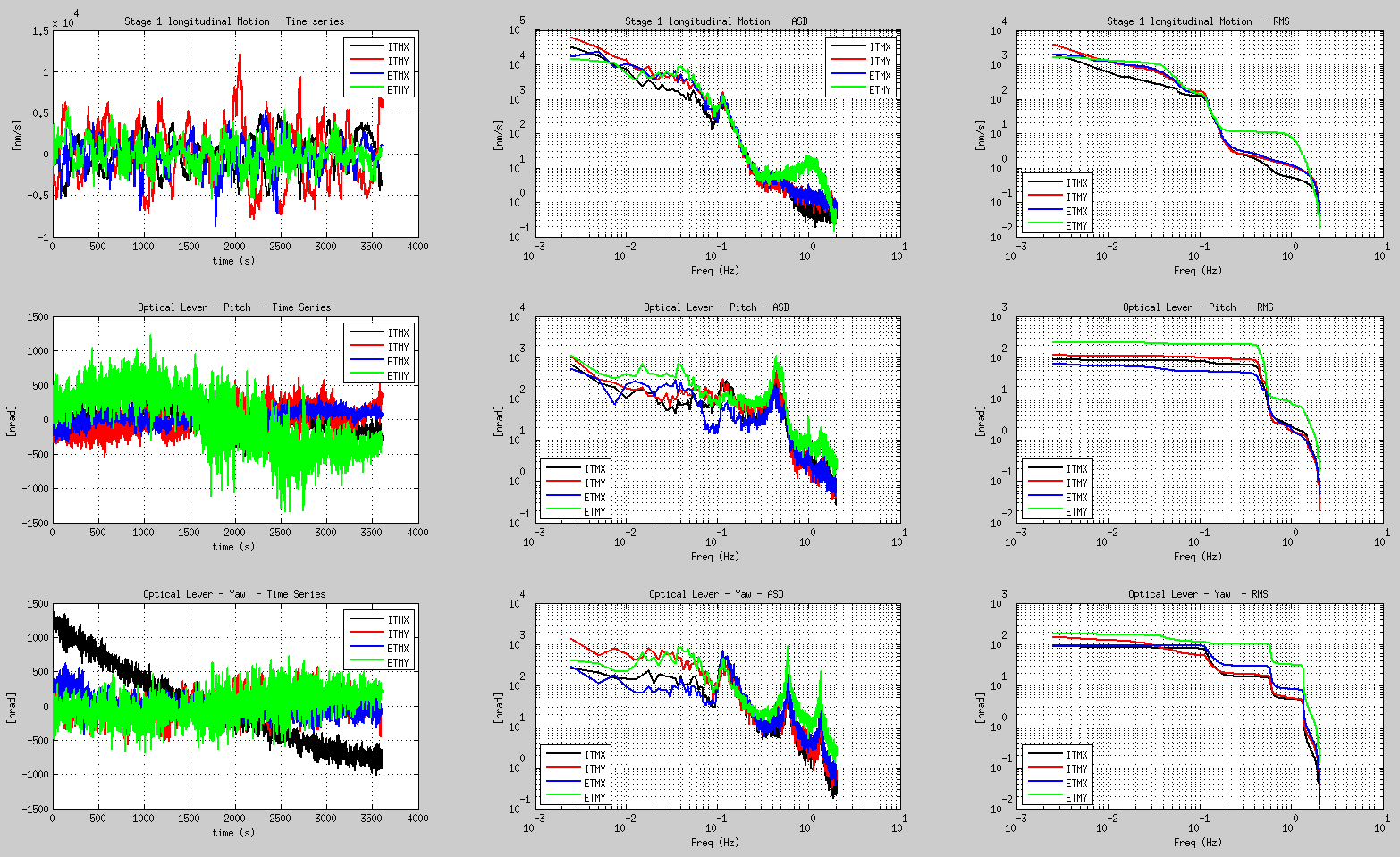
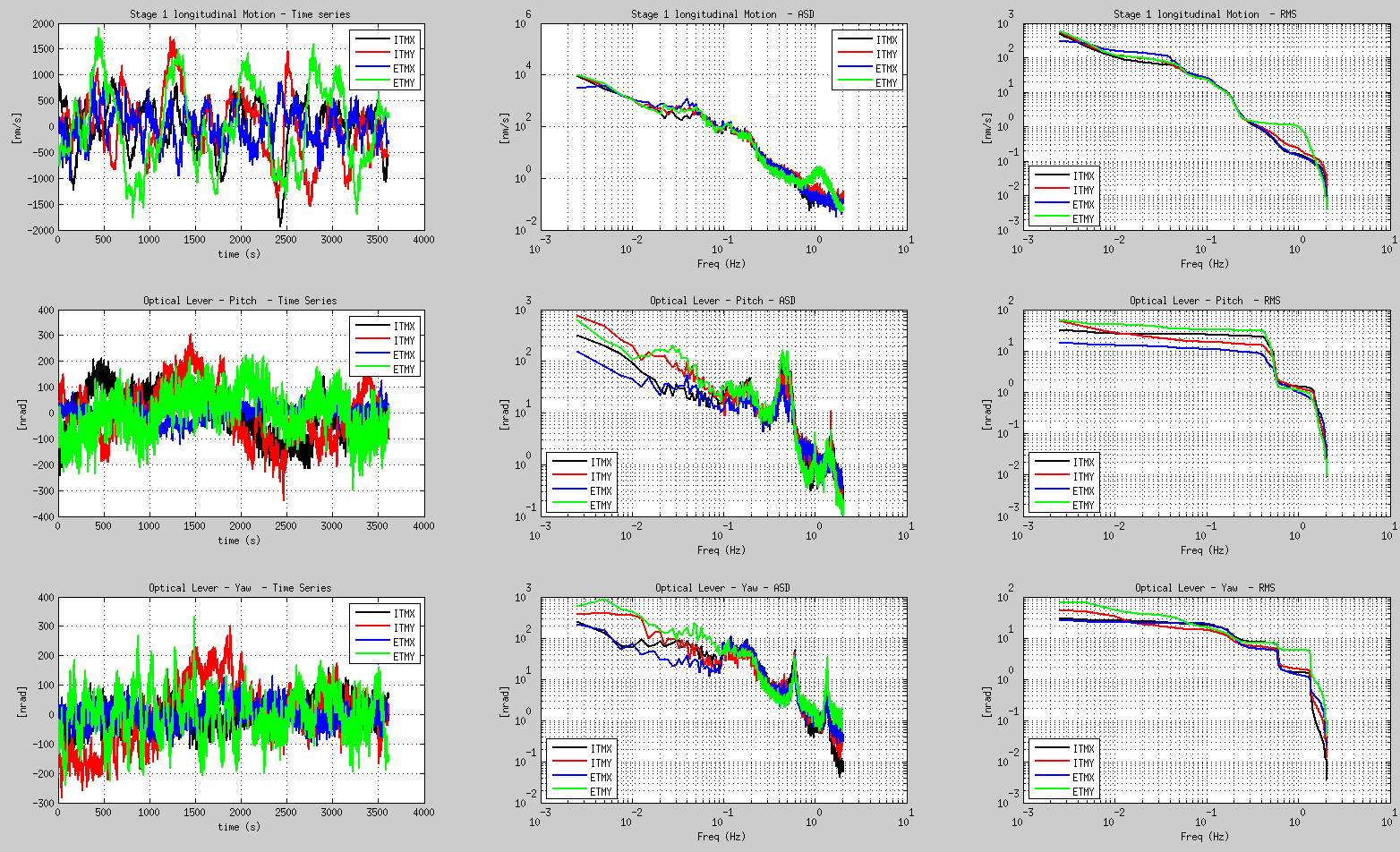
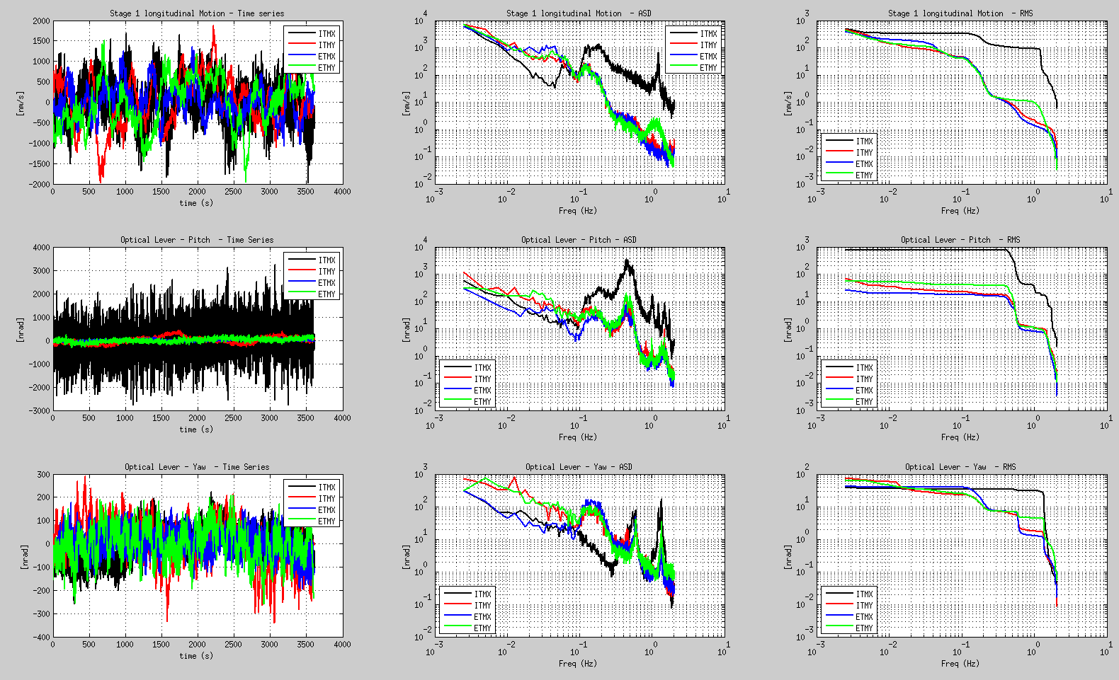
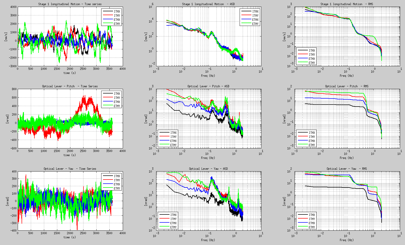
There are 4 figures attached. Each one display one hour of data.
- The first figure is for the windy afternoon on Saturday October 11th reported by Sheila
- The second figure is for Sunday October 19th at 3am
- The second figure is for Monday October 20th at 3am
- The second figure is for this morning, October 21st at 3am
In each of the four plots attached:
- the three plots in the top row show the ISI longitudinal motion (along the arm axis). Left plot is time series, middle is ASD, right is RMS.
- the three plots in the middle row show the optical lever pitch motion. (Left plot is time series, middle is ASD, right is RMS.)
- the three plots in the Bottom row show the optical lever pitch motion. (Left plot is time series, middle is ASD, right is RMS.)
Comments:
Windy day (first plot):
In the first plot (windy day), the ISI stage 1 RMS motion is about 10 times higher than usual, around 1000 nm/s RMS instead to about 100 nm/s in normal days. The Stage 1 motion is dominated by features below 50 mHz, most likely tilt as reported by Krishna.
The optical lever pitch motion is about a factor of 3 or 4 higher than usual (around 100 nRar instead of a few tens). Though the ISI is shaking at 50 mHz, the RMS of the optical lever is still dominated by the suspension mode at 0.5 Hz.
ETMY test mass pitch is moving twice as much as the others. This can clearly be correlated with the ISI motion at the suspension modes. We need to look into ETMY (something wrong in the blend? not enough loop gain? sensor noise?)
The test masses Yaw motion is dominated by features at the micro-seism, that are probably self inflicted (see comments for the third plot). ISI low performence on ETMY between 0.2 Hz and 1 Hz also affects the performance of the Yaw motion of this test mass.
Regular input motion, night time (second plot):
The ISI motion is pretty consistent from chamber to chamber, except for ETMY that should perform better above 0.25 Hz.
The Pitch motion of all test masses is dominated by the 0.5 Hz suspension mode.
The Yaw motion of all test masses is dominated by the micro-seism.
ISI off:
the third plot (data taken yesterday night) is quite interesting, as it looks like ITMY ISI was damped only.
In this configuration, ITMY pitch RMS motion is 10 times higher than the other units (near 1000 nrad RMS)
The Yaw motion is much lower (tens of nrad), but the three units isolated don't perform better than the unit damped. The unit damped is dominated by suspension modes features. The units isolated are dominated by micro-seism features.
Fourth plot (this morning at 3 amd);
all ISI are ON. They all perform similarly at low frequencies (below 0.5Hz), but optical levers RMS values are high and not consitent from units to units. Maybe some commissioning activities... to be checked.
Conclusion:
- we need to look into ETMY, and improve its performance at the suspension frequencies
- on windy times, and assuming alignment is the priority: for reducing the test masses pitch RMS value, we might want to try to improve the ISI performance at 0.5 Hz at the cost of further increasing the very low frequency motion. For yaw, we need to reduce the self inflicted amplification at the micro-seism.
- on regular times, we need to reduce the apparently self-inflicted yaw motion at the micro-seism