hugh.radkins@LIGO.ORG - posted 18:00, Tuesday 07 October 2014 (14349)
WBSC ISI Overview medms updated
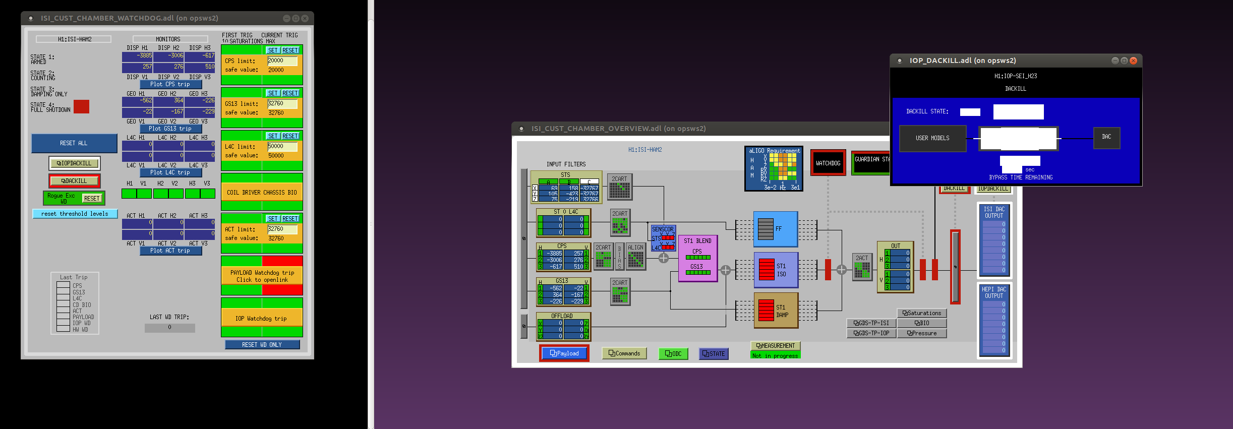
ITMY on the SITEMAP was pulling up ISI_CUST_CHAMBER_OVERVIEW_Z_to_RZ_Decoupling.adl rather than ISI_CUST_CHAMBER_OVERVIEW.adl (this is the misfortune alluded to previously.)
I corrected this on the SITEMAP--you'll need to get a new one.
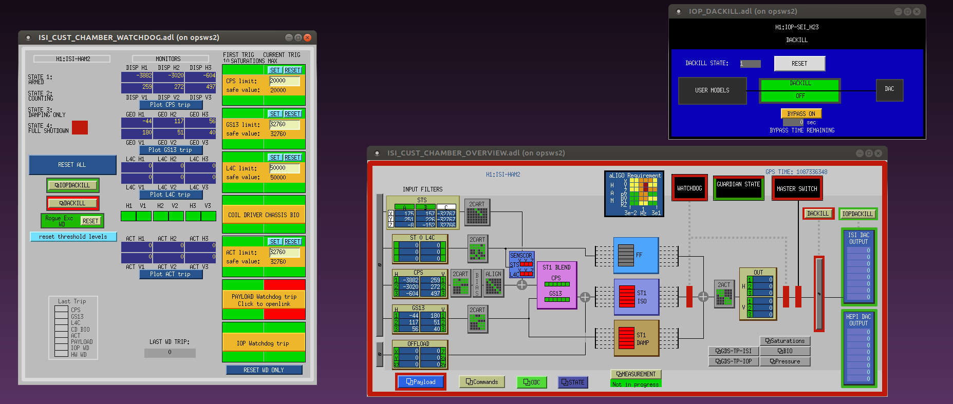
Additionally, ArnaudP, our old friend, landed a nice chunk of guardian realestate on the overview, very nice, thank you AP!
And with my corrections noted in the previous log below, the IOP DACKILL notices are all useful now.
SITEMAP and the OVERVIEW medms are committed to svn.


The CDS overview MEDM screens (large and small) were modified to include the new end station CAL models. Also the h1oaf0 was modified to put in place holders for the GAMMACAL and CALCS models which will be installed soon.